This was one of those jobs that you thought it was a good idea at the time, once construction started and things didn’t go as planned, I wished I’d never started it and the only way out was to spend your way out!
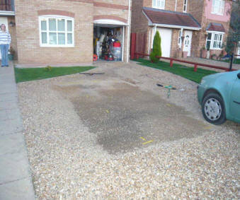
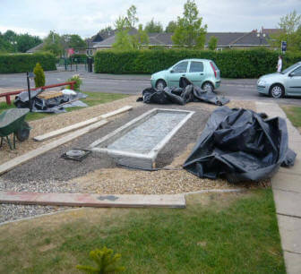
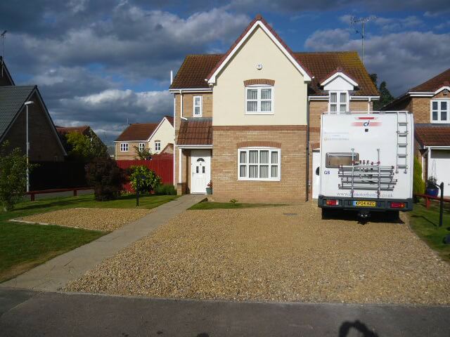
April 2011 was day one, the plan was to sink a vehicle inspection pit into the drive so that when it’s not in use, it would be completely covered and therefore unnoticeable, the pit had to be narrow enough to take the small car we had (Fiat Punto) but robust enough so that when our 3.5t motorhome was over it the walls didn’t collapse with me in it, also it had to be the correct height that I could work under the car or van comfortably and the right length that I can get to at least half of the underside of the van without it sticking out across the pavement (sidewalk for US visitors).
Planning
First stage was to confirm that planning permission didn’t apply, which it didn’t and secondly that there were no buried services that could stop the project, I did lift manlids to check the direction of pipes and wrote to the gas, electricity, telephone and water utility companies and all came back ok, the only thing I had to move out of the way was the armoured conduit which goes to the outside lights which was easy as I’d fitted it.
If the pit was nearer to the house or impacted on the house footings, Building Regulations may have come into play, as it was the pit was over 4m away from any external wall, so no issues.
Design
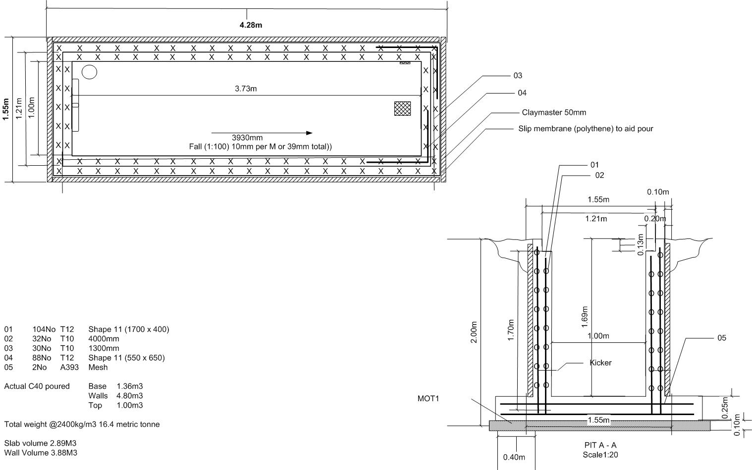
One the dimensions were decided on, I started researching the reinforcing steel bars and type of concrete required, from this I drew a rebar plan which gave me the quantities of steel and concrete needed.
I did explore using a ‘tanked’ construction and simply digging a hole and sinking it in, what bothered me was the high water table we have here and if you google ‘hydrostatic pressure’ their are examples where swimming pools have simply been pushed out of the ground, not a good look!
I opted to use 18mm plywood to make a ‘shuttered’ form even though the wood would be wasted, on balance it was still cheaper than hiring in bespoke steel panels from a local supplier.
Build
The following series of pictures show the construction from the marking out of the hole to the finished pit, I mentioned at the start about things not turning out as expected, I made a flawed assumption that after the hole was dug, I could get away without propping the sides (I know it was stupid!), anyway fortunately I wasn’t in the hole at the time, but the sides caved in, now the problem this presented was that the cost to fix this.
The cost escalated as I would need a JCB rather than a mini digger to scoop out the spill due to the now extended boom reach required, also I would need two more 12m2 skips at £110.00 each, not to mention the additional backfill to make good the sides where the clay had slid from, all in all a blinking nightmare, so, do I fill the lot in and cut may losses, ore spend out of it, well the rest is history and a year later the credit card was finally paid off :-).
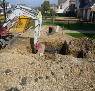
Outline marked out
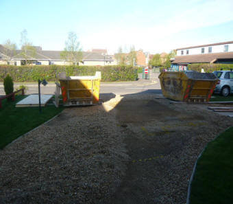
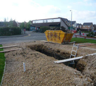
Two skips ready for the spoil.
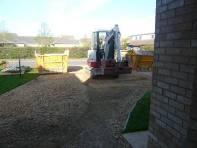
Mini digger and driver ready to start.
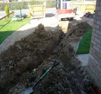
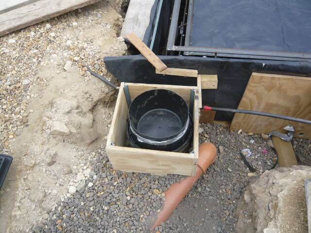
First trenches dug, one to pick up the power, compressed air lines and sump pump delivery pipework to a drain, the other trench was for the 6″ vent pipe to the base of the pit.
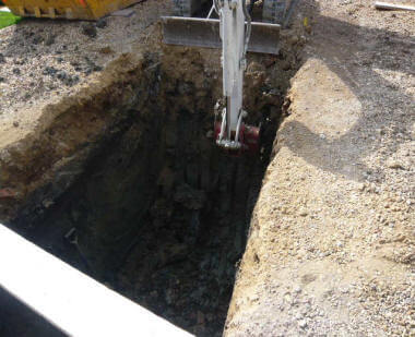
Main pit dig started
The driver did a very neat job.
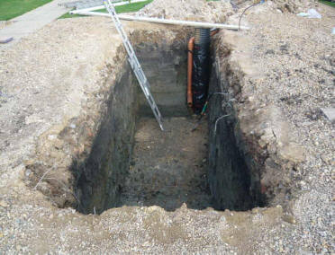
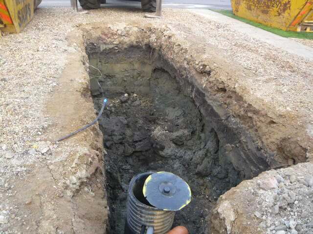
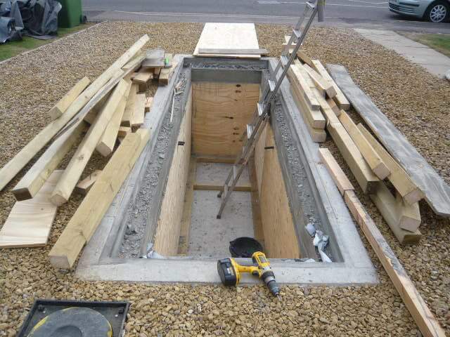
All dug out and ladder down for inspection.
Completed Holes, the brown pipe is from the fresh air vent stack.
All done – spot on digging job, brown pipe is for the air vent and the Black tube is for the submersible pump to pump the pit out as their was no intention to make it waterproof.
Big Problem!
Everything was going so well until the sides collapsed due to the clay drying out.
Pit sides caved in the day after it was dug as I didn’t support them, the ground is heavy clay which slipped leaving a overhang, this overhang was soil and hay as the land on which the house was built used to be a farmers field.
Workaround
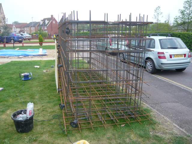
So, change of plan, I decided to build the steel work outside of the hole and surround it in shuttering ply, and have the digger lift it into the hole……
Start of cage construction
Lin looking happy to help
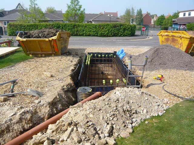
JCB with longer reach than a minidigger to clear the collapsed hole
Side shuttering ongoing
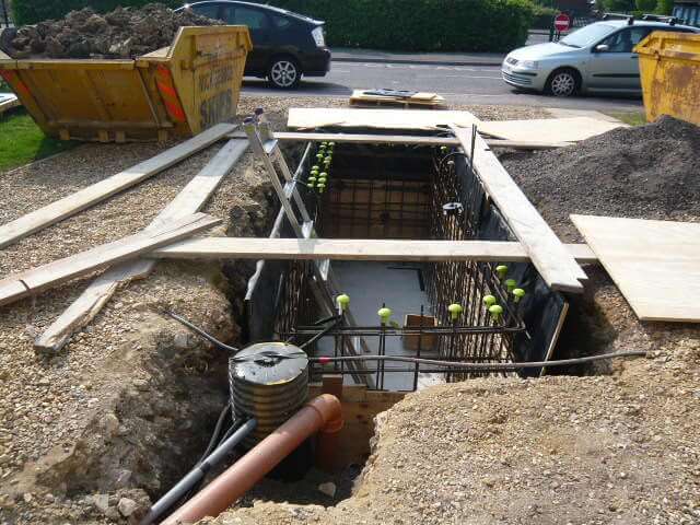
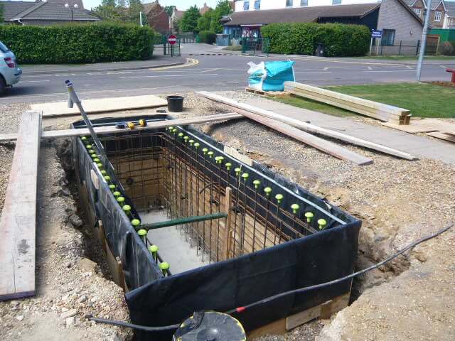
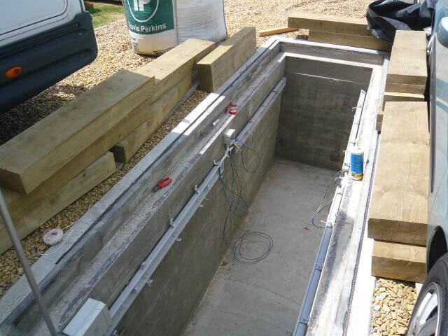
With the cage lowered in, the base was concreted in with a raised ‘kicker’ lip created by formwork, this enabled the wall plywood to be pushed against this, supporting the base of the wall section.
As I didn’t know the cubic meterage of concrete required, I opted for a company that mix on site and you pay for what you use – Cardinalis.
Wall shuttering in place
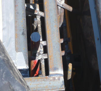
Rebar welded to angle iron edge protectors
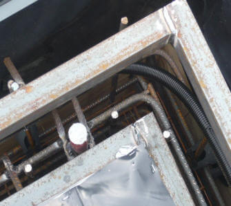
During the wall shuttering, flexible conduit was installed for pit lighting, power socket and compressed air line.
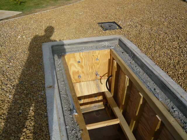
During the shuttering of the access end wall, I drilled holes in the plywood and pushed in waste pipe, the holes left when the form is stripper will be for the Step Irons, also you can see flexible conduit sticking out from the garage which will bring power and compressed air to the pit,
Stripping of the forms, very exciting part of the project, three separate pours were used, the first was the base including ‘kicker’, the walls were then shuttered and the second pour was for the walls, the final pour was to build up to the finished level and form the lip for the wooden sleeper pit cover.
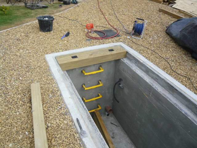
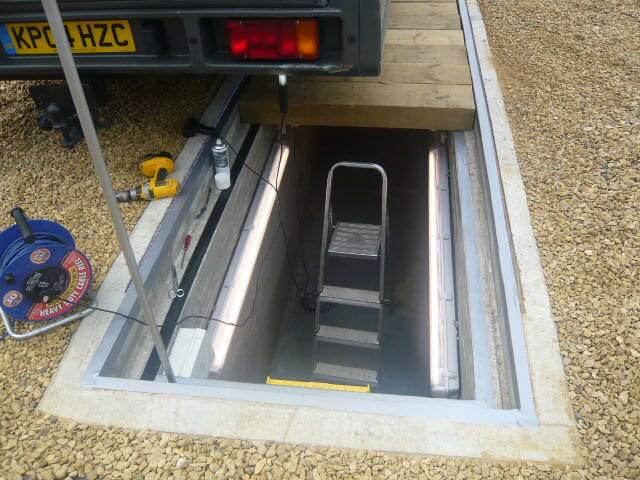
The picture shows the fitment of the removeable sleepers and the ‘Step Irons’ down into the pit, the Step Irons were cemented in the holes with a high strength/ rapid set mixture.
Fluorescent lights being fitted to the walls of the pit, however, due to the damp atmosphere, these were removed at a later date.
First job was to repair a broken molding.
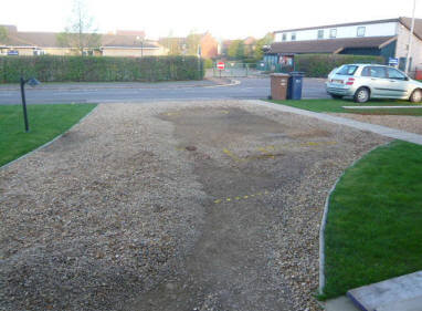
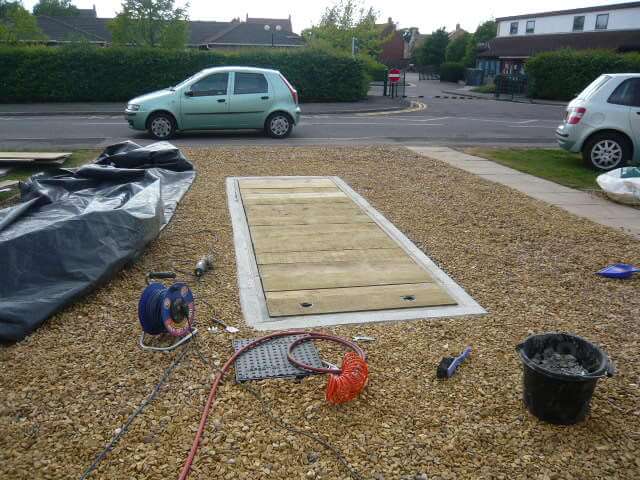
All finished, with the pit boards on and lightly covered with gravel. everything blends in.
Update
Move the clock forward to 2022, some 11 Years after I initially built the pit, the motorhome had well gone and I’ve changed my car so their is no need for the pit now, however, it has come in very handy in an unexpected way.
I have re-seeded my front lawn and these needs copious amounts of water to keep it healthy, as we are on a water meter, I turned my attention to the volume of water in the pit, this is made up of ground water and surface water getting into the pit.
It turns out that I have approximately 5,643 litres or 1,241 gallons of water storage on my drive, so I bought a pump and reduced the metered water on the lawn :-), plus I have now linked it to my my lawn irrigation system.
An added bonus is that the pit will refill due to the local high water table also I have bought a stopple for the rainwater drain, this means that rainwater from the roof will, instead of going into the surface water drain, it will use a redundant ‘pump out’ line from the pit to drain, as a ‘fill’ line’ instead.
The other thing to mention is that the original wooden pit cover swelled and rotted so needed replacement, I used 125mm sleepers and had the sawmill cut these to 1160mm which is slightly shorter than the original sleepers, hopefully this will leave enough room for expansion should they swell in the future.
The cost of the sleepers from Brigstock Sawmill was just under £300.
I have been after getting a Smart Meter installed for the past few years so I could monitor my energy usage in near real time, my original supplier (EON) said that as my gas was supplied via IGT infrastructure, they could not install Smart Metering, speaking to British Gas (BG) and my IGT they said this wasn’t a problem, so I switched supplier.
Surprise, surprise, when I came to register for a Smart Meter to be installed British Gas, they said it was not possible for the same reason that EON gave.
I took the case to OFGEM, but my case was undermined as the telephone conversation recording with the BG operative and myself could not be found, however, due to an extensive e-mail trail, OFGEM ruled that BG were to give me a written apology.
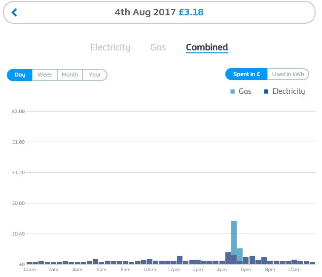
Winding forward to the 24 August 2017, I upgraded my British Gas mobile app and ‘Book a Smart Meter’ button appeared, with a wry smile I pressed the button and hey presto it accepted my booking, whereas previously this has been declined, and an appointment was set for 3 August 2017 between 13:00 and 17:00.
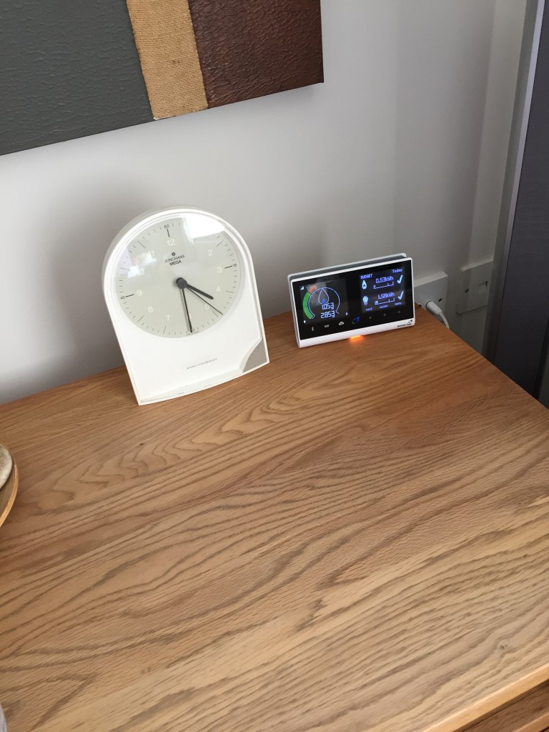
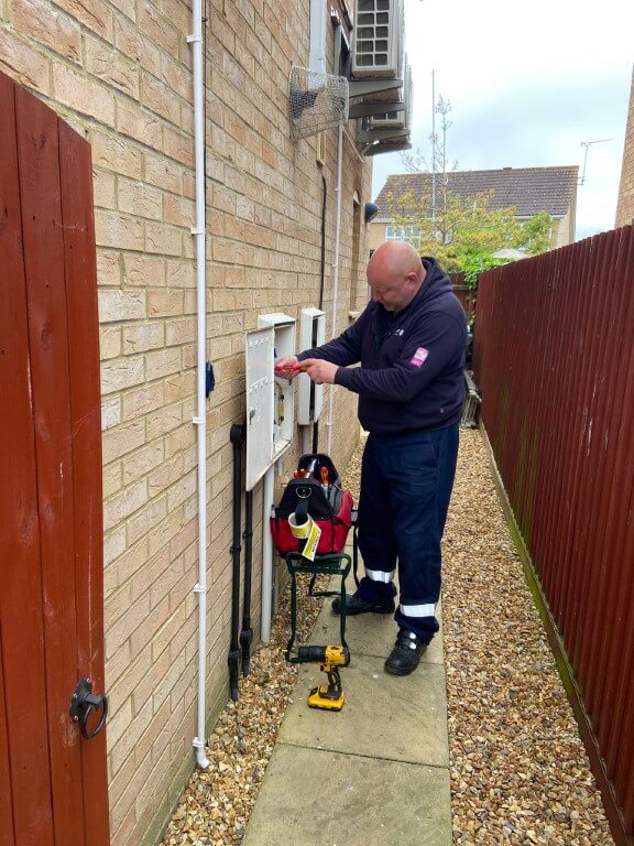
The BG guy rang before he arrived, he introduced himself as Ashley and was really friendly, taking him to the external meter cupboards I had my fingers crossed that nothing would get in the way to causing a cancellation, as it was, no problems were presented so the installation of gas and electricity smart meters could go ahead.
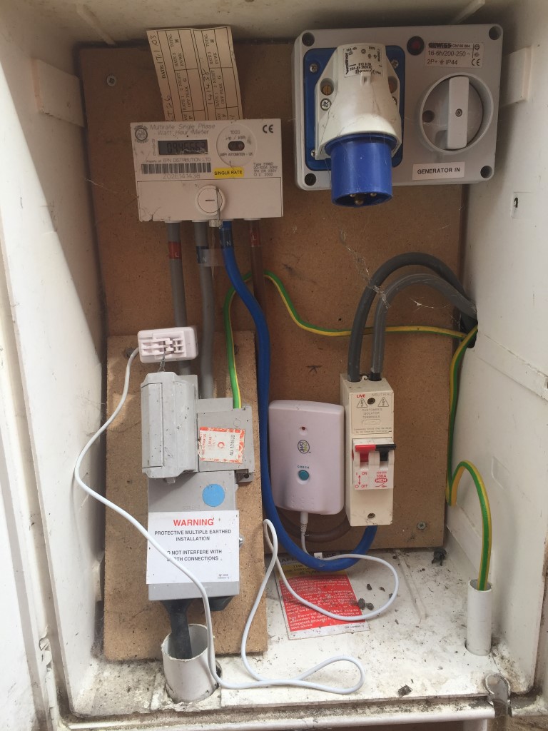
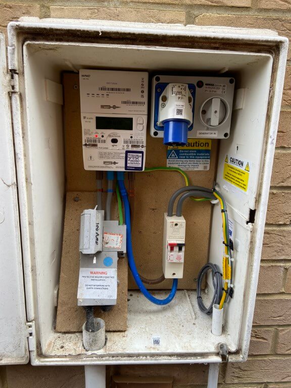
The picture above shows my old meter with an OWL energy monitor transmitter with a clamp on Current Transformer attached to the incoming phase wire, Ashley started on the electricity meter swap out first after checking the nearest socket with a plug in tester for confirmation of correct polarity and earth continuity, he turned off the consumer units main isolator and central heating boiler before pulling the main service fuse.
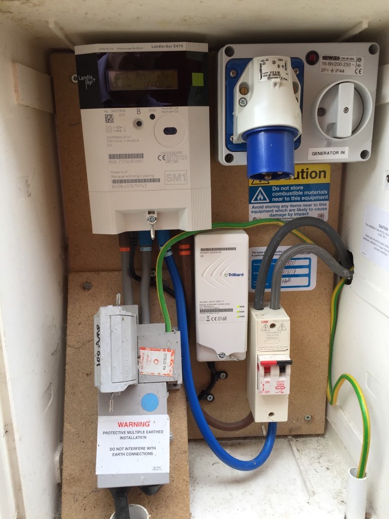
Due to the larger size of the smart meter, he had to shorten the tails from the cut-out, apart from that, the exchange took about 40 minutes in total and the OWL monitor is now redundant!
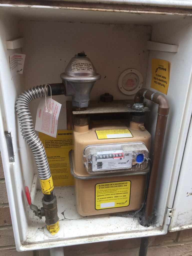
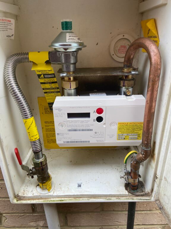
The replacement of the gas smart meter was a bit more challenging as the new meter would not fit without meter exit pipework modifications.
Ashley isolated the gas supply and stripped out the old meter, regulator and anaconda pipe, replacing the regulator and pipe with new, he offered the meter up and noted where the meter outlet pipe needed modifying.
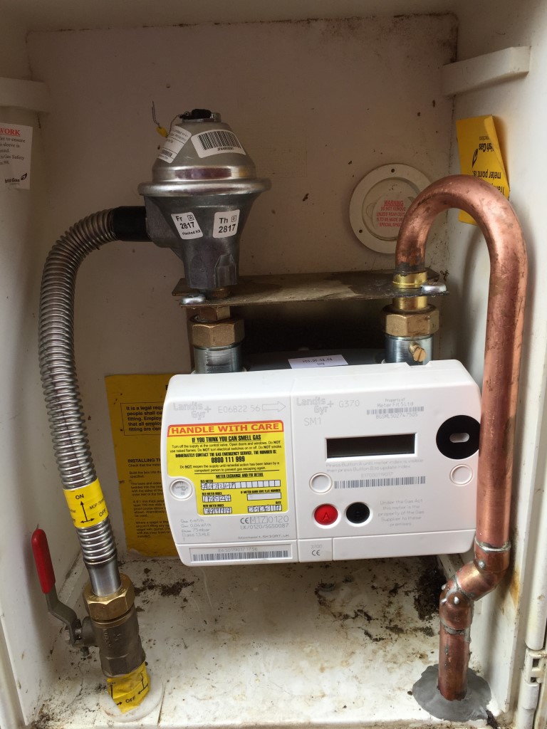
He cut out the existing pipe and soldered in a prefabricated swept connector and it was a perfect fit.
Link to Landis & Gyr Gas Meter Information
He tightened all connectors after replacing all ‘O’ rings with new ones and gave his works a pressure and leak test, once finished he sealed the outlet hole from the meter cupboard with flue cement.
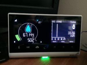
He then ran through the display and went on his way, overall it took about 2 hours to fit the two meters and one major positive was that he found a loose connection on the neutral from electricity isolator switch to my consumer unit, so well pleased that he did a quality job.
I opted for 1/2 hour reading to be captured throughout the day, the combined log is automatically uploaded daily to a remote server via the mobile network, logging into My Energy Portal (28/2/22 Portal Down)will allow you to see you consumption breakdown over time:
So, all done, its taken a few years to get and at one point I thought I would have to wait until 2020, fortunately I was wrong.
Updates
11 August 17, my mobile and online British Gas app no longer show half-hourly usage, instead they show seasonal overall consumption, I have raised a service ticket to see if this can be returned to as it was, the old IGT card was mentioned during my converstaion with the service desk and I said I have a screen grab posted to the internet, so I know it was working!!
16 August 17, Yeah!! My Energy portal is back working showing 1/2 hourly usage figures.
4 September 17, noticed that the gas reading was not being updated on the remote display after 30 minutes of use, it to update with all the reading the next day and then at random times the gas icon would light, BG coming out on 2 Nov 17 to replace the display.
3 November 17, indoor display changed by BG but he could not wait the 30 minutes to see if gas registered on the display, unfortunately it still doesn’t update.
14 November 17, spoke to BG Smartmeter department on 0333 2029821 and there is nothing that can be done to get my display to show gas readings every 30 mins, they are working on the issue, but as yet there is no fix. Meter consumption readings are updating via the Vodaphone network ok.
I’m disappointed as the display does not give the functionality as advertised, but it is free so I’ve nowhere to go with this.
16 December 17, not sure if its a fluke or not, plugged the display in upstairs and after a week or so of not showing gas being used, it suddenly started working, then stopped again!
8 May 2024 – Smart Meters Upgraded
I changed energy provider to Octopus some time ago and was used to giving online meter readings on the 22nd of every month, I did notice on the Octopus App that my SMETS1 electricity meter was sending readings but this was not the case for the gas meter.
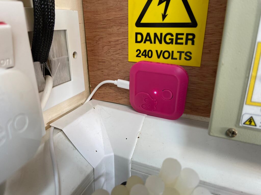
After considerable correspondence with Octopus over a protracted period of time, finally a date was fixed to replace my existing meters with SMETS2 smart meters, also I was getting a new In Home Display and I asked for a Home Mini to interface into Home Assistant.
The meter fitter was very chatty and happily answered all my questions, after conducting electrical and gas safety checks on the house, the meters were swopped out.
The SMETS1 electricity meter had a separate communications module, the new meter has this module plugged into the top of the meter making for a more compact installation.
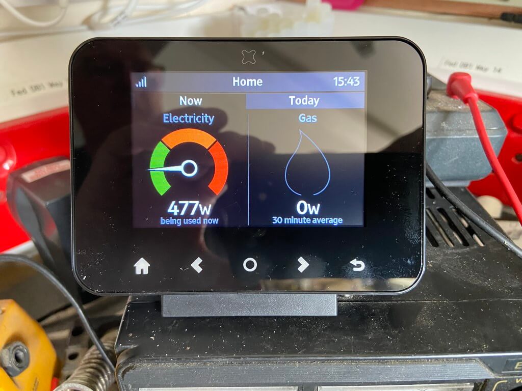
The main difference is the display scrolls every 8 seconds, so no button to press to get your meter reading, you just wait until it shows:
Time > Date > KWh > Inactive >
No obvious changes to the gas meter apart from a slightly more angular housing.
In Home Display
This is a third party item, supplied by Octopus but made by geotogether.com, a Geo Home App is available for the In Home Display and it uses an inbuilt Wi-Fi module accessed via the settings menu, once a geo home account is setup, your mobile device will show all the readings on the App.
This works really well as the signal strength drops significantly is I move the In Home Display fore than a few feet away from my meter.
The Octopus App also shows the meters data, with or without the In Home Display.
The Home Mini has been developed by Octopus and enables greater information to be downloaded about your energy usage, I use Home Assistant and this interfaces perfectly.
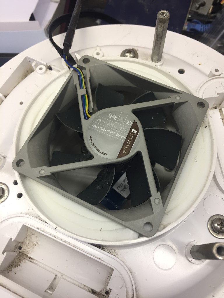
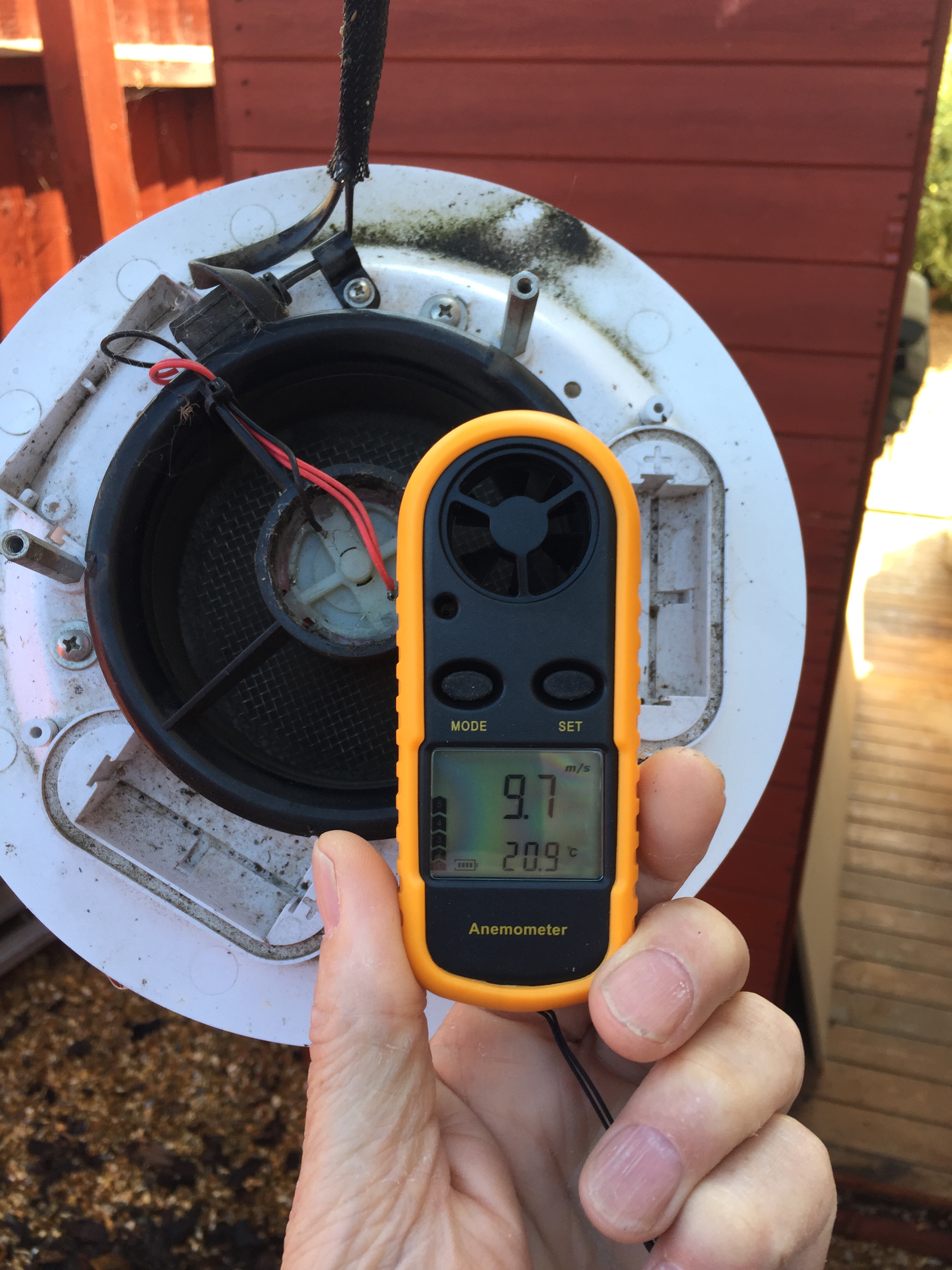
When the original Davis FARS motor failed I installed a new motor and kept back some spare motors, waiting for the inevitable motor failure to occur, reading online, changing from the Davis Fan to a PC varient made a lot of sense and not only is the life of motor excellent, but it is possible to monitor the motors output for operation.
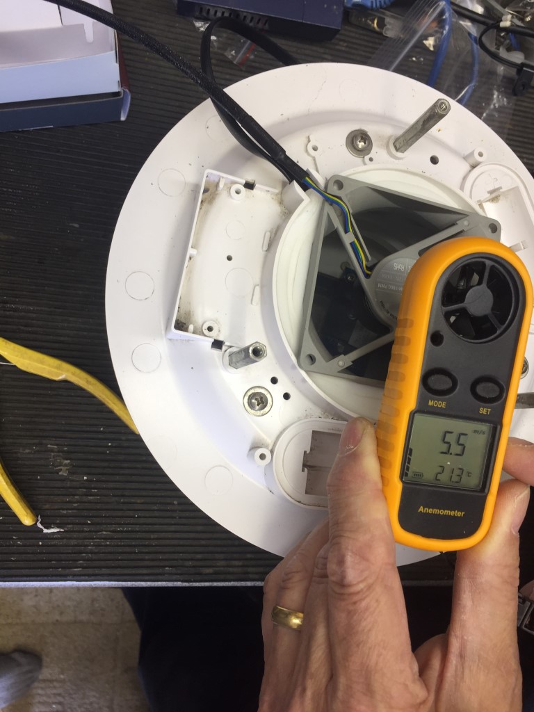
I was interested to know the existing Davis fans air flow, mine was running at 2.4vDC and showed 9.7m/s:
With the David FARS removed, the existing fan assembly slides out of the housing as a complete fan & surround, the hole left will take the 80 x 80mm fan with only a very minor filing of the fan case body to make it slide into the body of the FARS.
No modifications are made to the existing FARS body allowing reversion back to the existing fan if I wish (can’t think why, but you never know!).
To form a seal around the gaps, I used self adhesive door/window strip seal.
The finished fan after the seal is applied and checking that the fan is sucking, rather than blowing:
The oringinal fan ran on 2.4v, I replaced the voltage regulators fixed value resistor for the correct one to give 11.54vDC output and this feeds the motor and the motor monitoring Tacho.
The air flow of the PC fan when installed and connected was 5.5m/s, this is less than the original davis fan, but this is still better than static air within the sensing chamber.
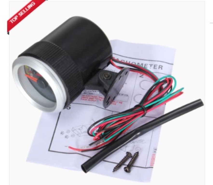
The Davis weather station I have is the wired version, and I used Cat5e cable rather than the supplied 4 core cable from the ISS to the console, using the Cat5e unused cores, I fed the supply voltage to the fan and the Tacho pulse into the house where they are connected to a 52mm (2″) counter tachometer guage RPM, this was bought off eBay for £6.70 + £1.69 postage.
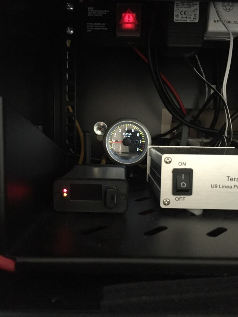
Tacho installed in the equipment cabinet:
The PC fan connections are:
Black – Negative 12v
Yellow – Positive 12v
Green – Tacho Pulse
Blue – PWM (Not Used)
The Tacho is set for a 4 cyclinder engine using a switch on the back of the unit, with the fan running the backlit RPM display is showing just under 1000RPM (reading slightly low due to voltage drop introducd by the distance from the ISS to the end point), to the left of the Tacho is my Meteobridge Pro weather station server to the internet.
The motor is guaranteed for 6 years, replacement will be very easy and I’m able to remotley monitor that the fan is functioning, all for less than £20.
Update
16 September 2018, after 14 months continuous use, the motor failed, not even close to 6 years!!
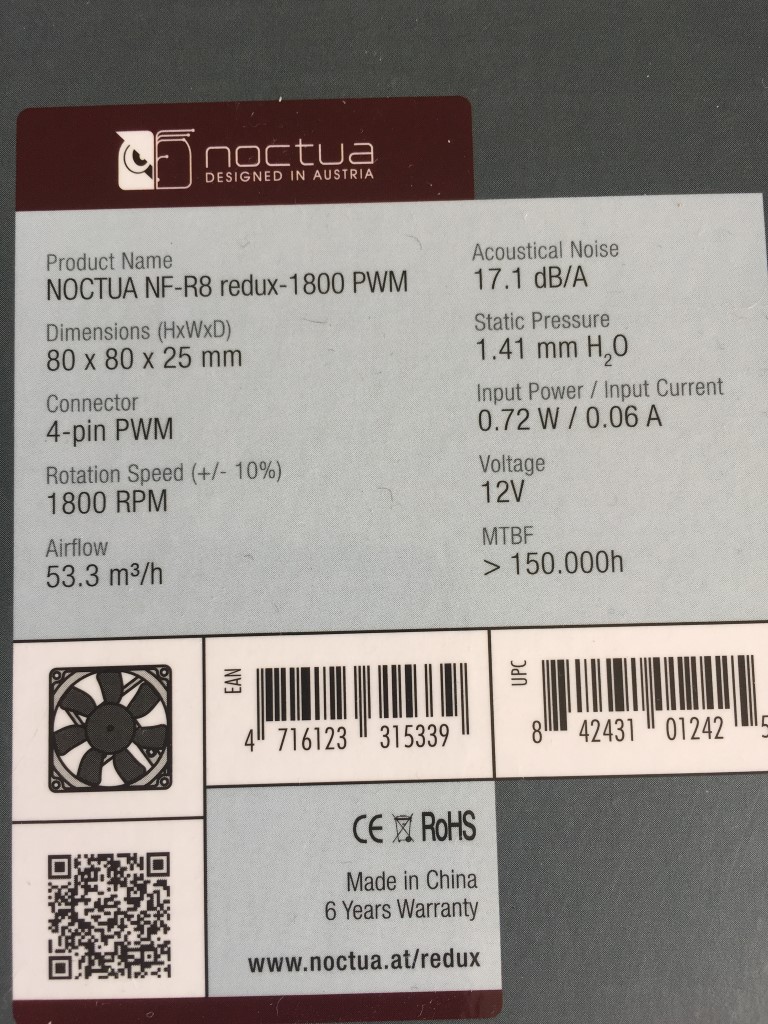
I wrote to Noctua who are based in Austria and after asking me to perform some basic fault finding and requesting the fans data markings, agreed to send me a replacement fan, I in return was asked to send then a picture of the faulty fan with some of the blades broken off when the new one arrives.
While this correspondence was going on I bought a new fan off eBay for £12.50 which was installed on 22 Sept 18.
Update 2
12 April 2020, whilst we are in virus lockdown I thought I’d clean and service the weather station and I noticed the fan had stopped working, so replaced it with the one sent to me by Noctura a couple of years ago, looks like the average continuous running life is two years for these fans.
Update 3
30 March 2021, Nocura fan gave up, so much for a 6 year warranty, decided to go with a cheap and cheerful PC fan off eBay for £5.83.
Update 4
16 October 2024, Reverted back to a standard unmonitored 12vDC PC fan (80 x 80 x 25mm) – Amazon £8.98.
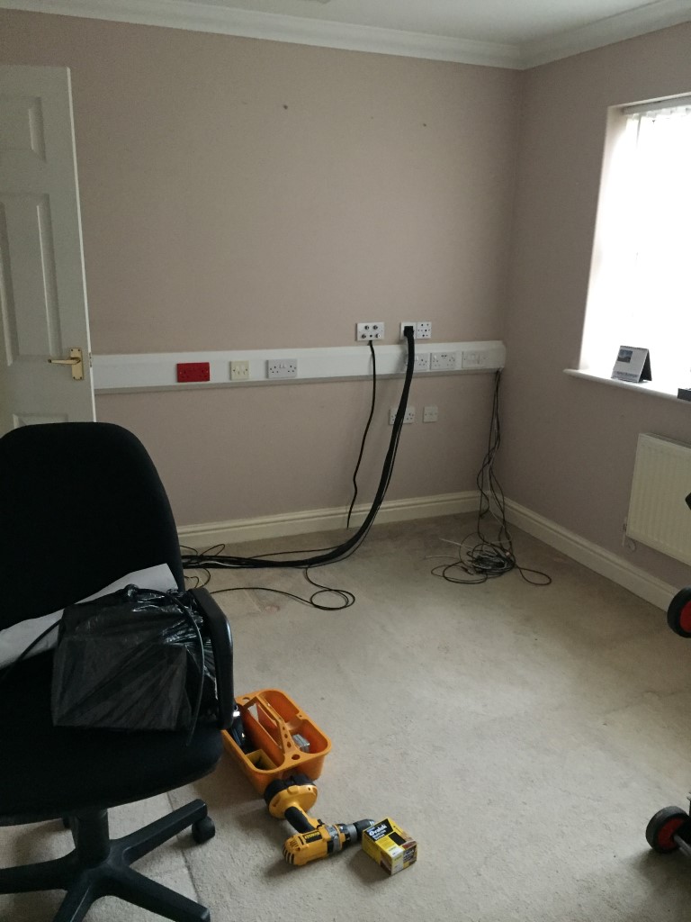
My home office is also my shack and like most things, the infrastructure grew rather than was managed, so I knew the electrical power was not ideal and the network patch panel was full. The thing that brought it to a head was the need for a new floor covering, and so it began.
First job was to put in a new final circuit ring main to the office dado trunking and add a couple of additional power points for the UPS and mobile air conditioning unit.
As the cables are ran in the loft, I decided to install a decent fold down loft hatch and sliding ladder for ease of access, the loft lighting was also improved by installing 4 x 4′ fluorescent operated by a pull switch fed from its own dedicated circuit, this lighting made a huge difference.
To move everything out of the office to get access to the floor meant it needed to go somewhere, and the obvious choice was the loft, so off to Homebase for loft flooring and loft legs and of course it was boarded during the hottest days of July.
Once everything was out, I could start tearing down to rebuild:
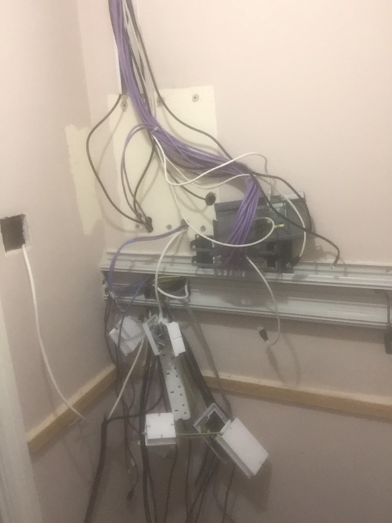
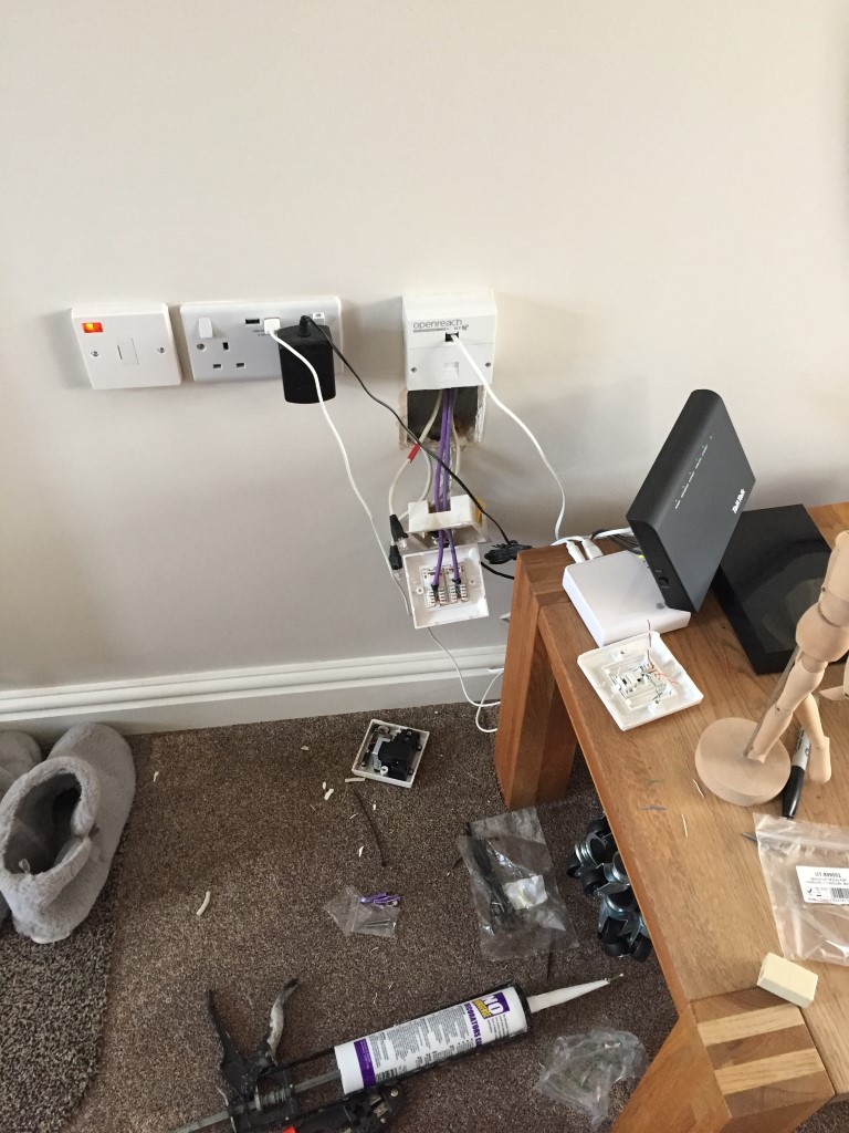
The existing home network hub needed to come out:
No going back now!
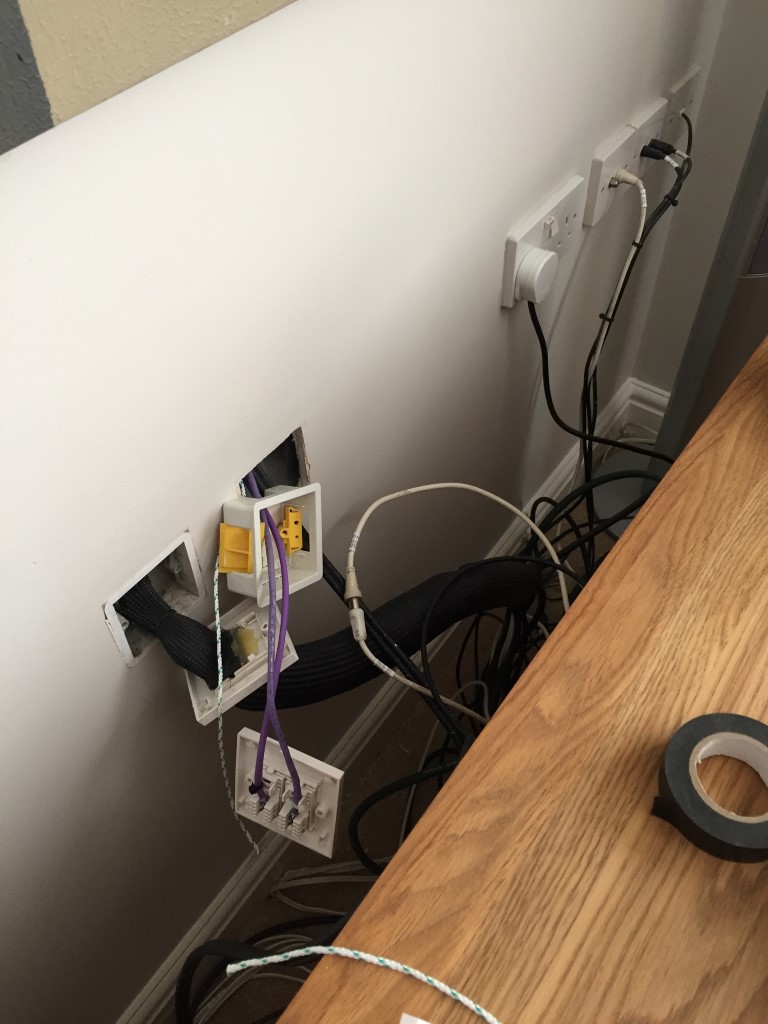
New cable drops for additional tap points near the TV and existing TalkTalk router are shown, I did move/rationalise other tap points around the house and in the garage. In the lounge I drilled through to the external wall and installed conduit in preparation for when Virgin Media install fibre to the home.
The network cables were in and tested using a cheap and cheerful wire mapper and did find a faulty tap point, so well worth £2.59.
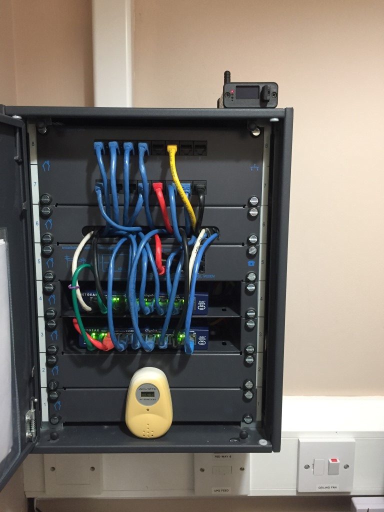
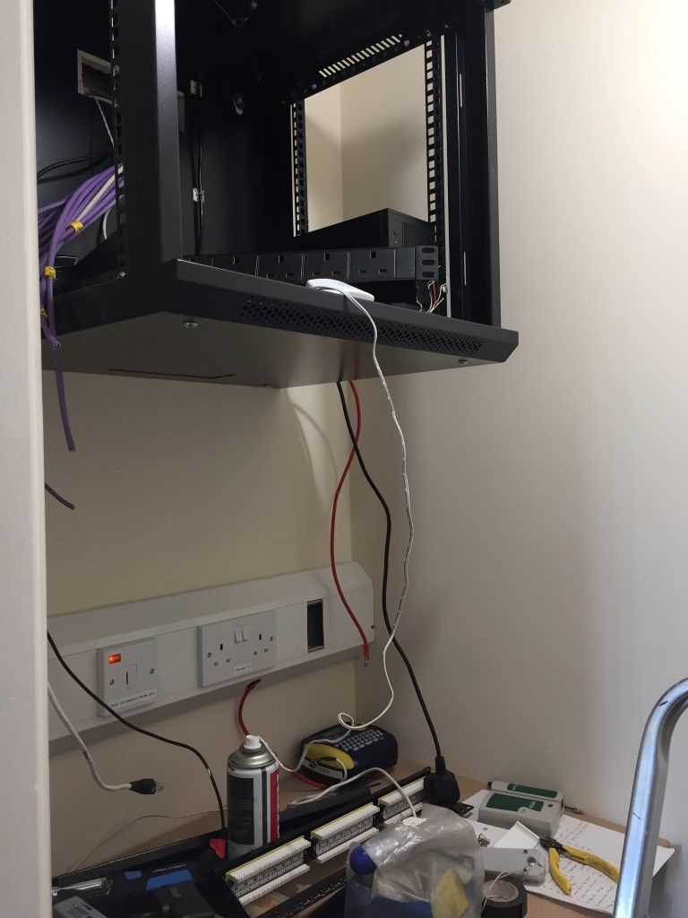
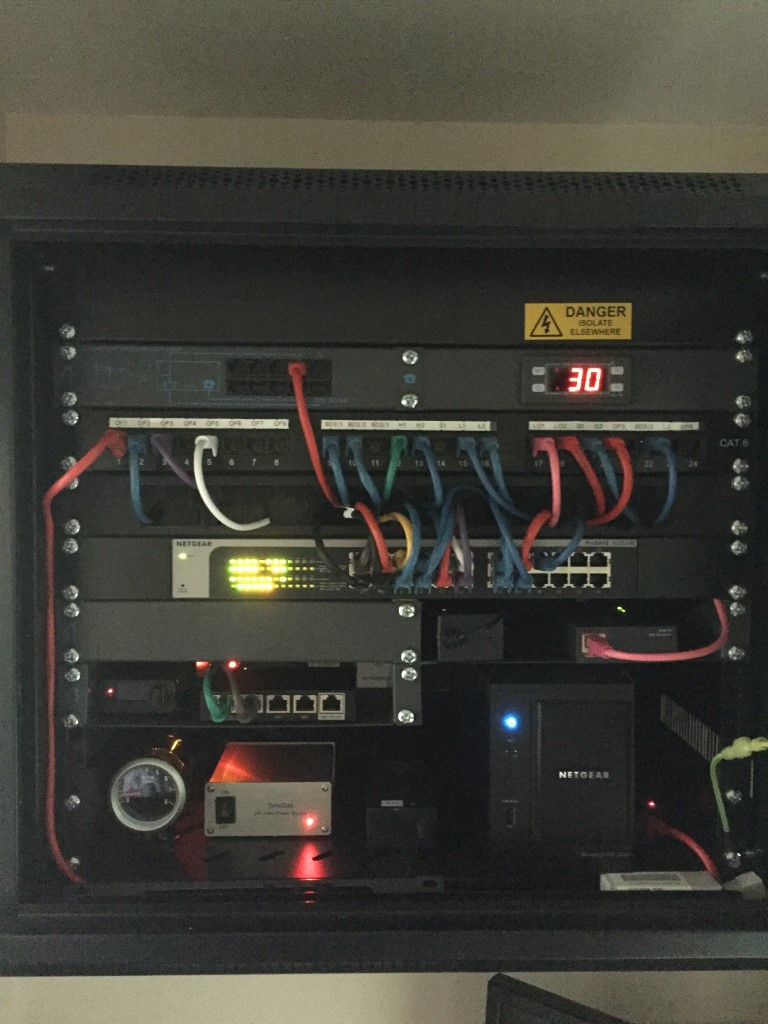
Once the power was sorted out, it was time to start on the cabinet, this is a 12U wall mounted jobbie and cost £48.49 from eBay, the power distribution unit is fed via an 800VA MGE Pulsar Evolution UPS as is the red sockets.
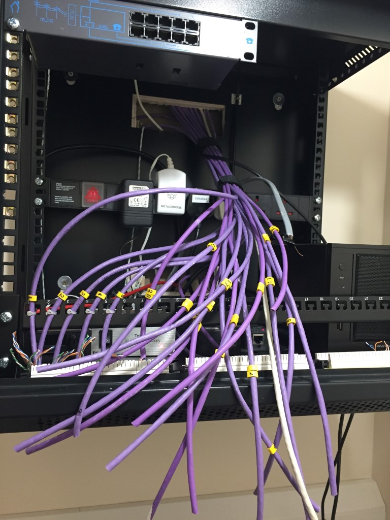
Cables identified and marked up, rather than numbering the tap points, I opted to use a convention which accommodated change easily:
OFnn =Office, tap point nn
BD2/nn = Bedroom 2, tap point nn
BD3/nn = Bedroom 3, tap point nn
LOnn = Loft, tap point nn
Lnn = Lounge, tap point nn
Gnn = Garage, tap point nn
Hnn = Hall, tap point nn
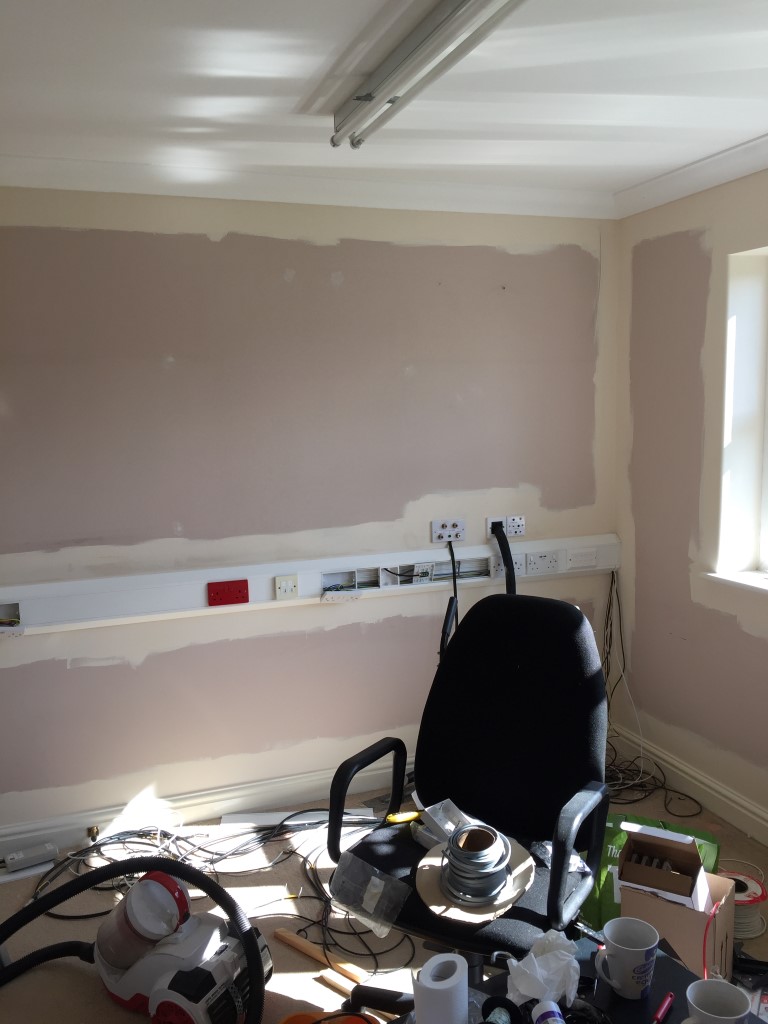
I, well me and my XYL took the opportunity to start to spruce the place up with a coat of paint as well. This shows the wall ready for the roller.
Wall cabinet finished, I added a small temperature controller which switches on the cabinet fan and the ceiling mounted fan within the cupboard where the cabinet is fitted.
Working top down:
2U blank plate
Telephone line IN, OUT via ADSL filtered ports
Temperature controller
24 port patch panel wired in Cat5e, two ports spare
Brush strip to hide surplus cable or manage surplus cable if your a purist
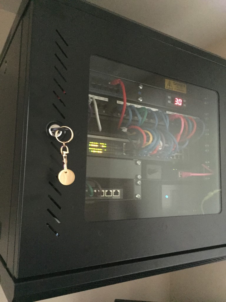
Cabinet closed and locked after making sure it didn’t hit the ceiling light.
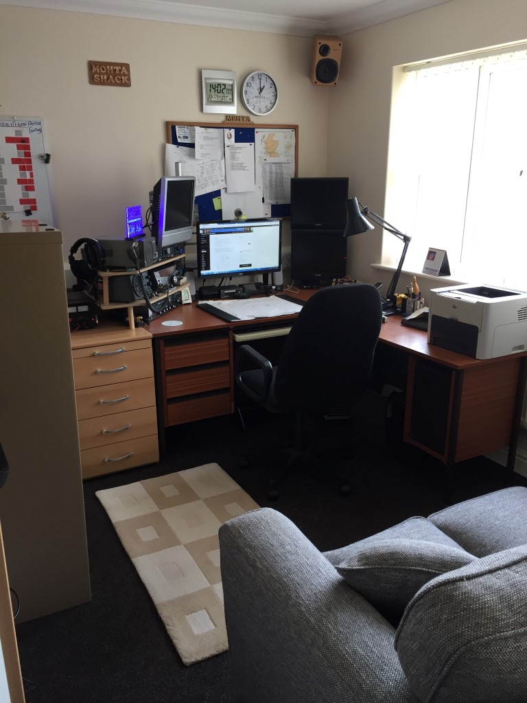
Room with everything put back in and tidied up.
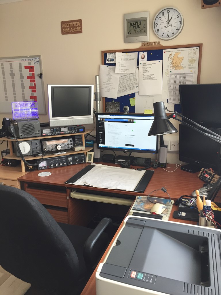
To make life easier for working on the radio equipment cables and connections, I didn’t push the desk right back to the wall and also no radio related equipment is on the floor (PSU), apart from the foot operated PTT.
Radio wise I didn’t do much, I added a separate 12v PSU for auxiliary equipment, such as the led signage, VSWR panel lights and SG autotuner to name a few, I also added a common RF earth board for the shack equipment to connect to.
Radio all put back together and cables tidied up, not sure how long the office will stay this neat 🙂
Update
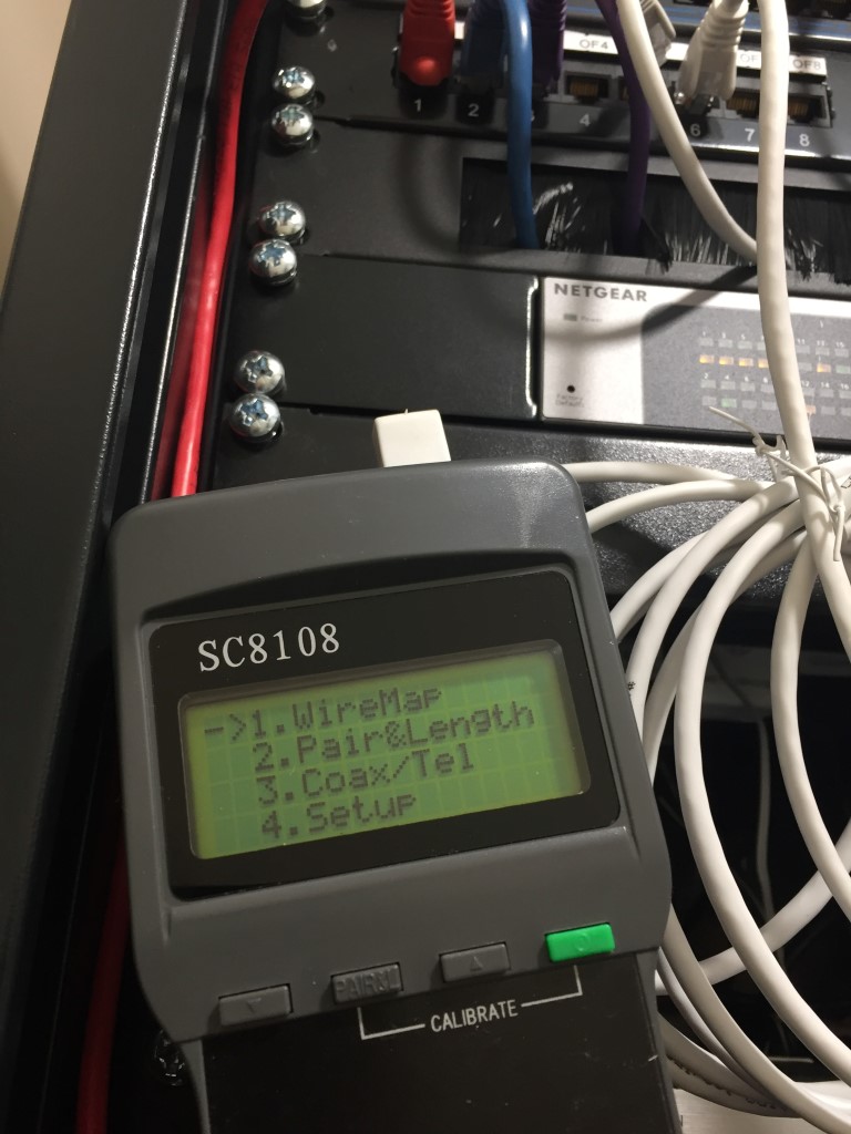
The cheap and cheerful cable tester unfortunately didn’t last the test of time and started giving some strange mapping indications, returning to eBay, I found a SC8108 Network Cable Tester for £17.98, this is superb value, and hopefully it will last longer than the last cable tester.
The SC8108 is very easy to use and has a number of useful, menu driven features, but for my small home network, wire mapping is the primary focus.
£17.98 SC8108 Network Cable Tester showing the mapping test results for a remote tap point from the patch panel.
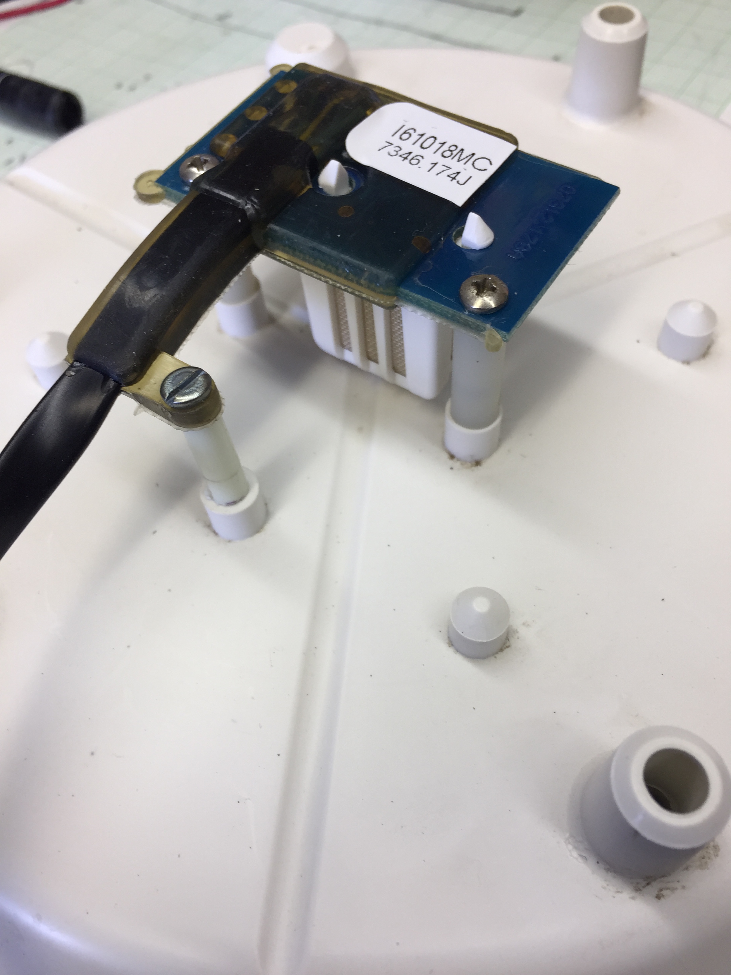
Humidity & Temperature Sensor 7346.070 replaced – Amazon £62.98
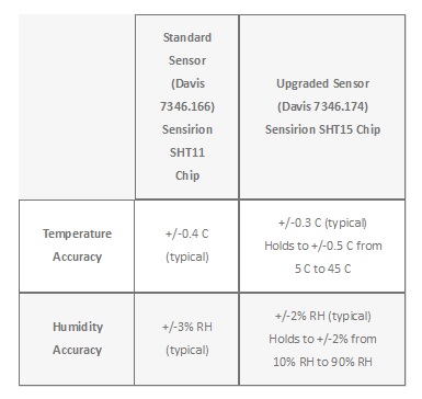
I decided to give the weather station a revamp, the two mini projects are the replacement of the Fan used to asperate the temperture/humidity sensor and the replacement of the original Davis temp/hum sensor with the more accurate chipset SHT15.
I bought the Davis 7346-174 upgrade from Scaled Instruments in Florida for $67.50 delivered (£51.94), the unit arrived very quickly as expected as I have used Scaled Instruments before and the service is exceptional.
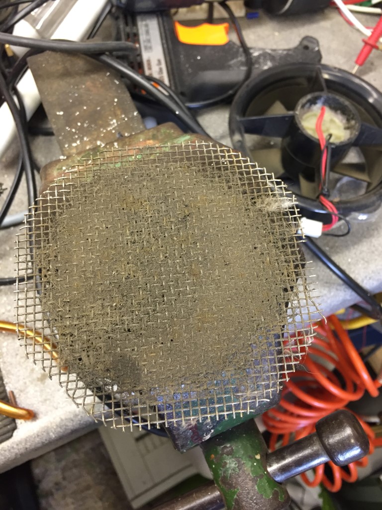
Disassembly was quite straightforward after putting the station in install mode, what I was suprised by was the amount of dirt that had been drawn into to the fan guard and other parts of the Stevensons Sheild which all need a good wash with soapy water:
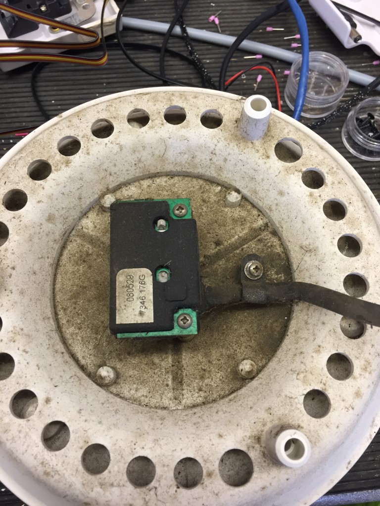
The original sensor is secured with two machine screws and the cable by a ‘P’ clip:
The replacement sensor was a direct fit as you wpould expects apart from the fact that instead of a ‘P’ clip, the environmental coating was used to form a cable clip, thit need a stand-off and additional machine screw to enable the sensor wire to be secured.
Once the housing was reassembled, sensor plugged up, fan reconnected and the station taken out of install mode everything worked just fine.
I’m awaiting the new fan to be deivered, so the second part of this will be blogged soon.
I was perusing the internet and came across a niffty idea to quickly identify which Cat5 outlet was connected to which port on a patch panel, so, as I had the parts, I thought I’d have a go.
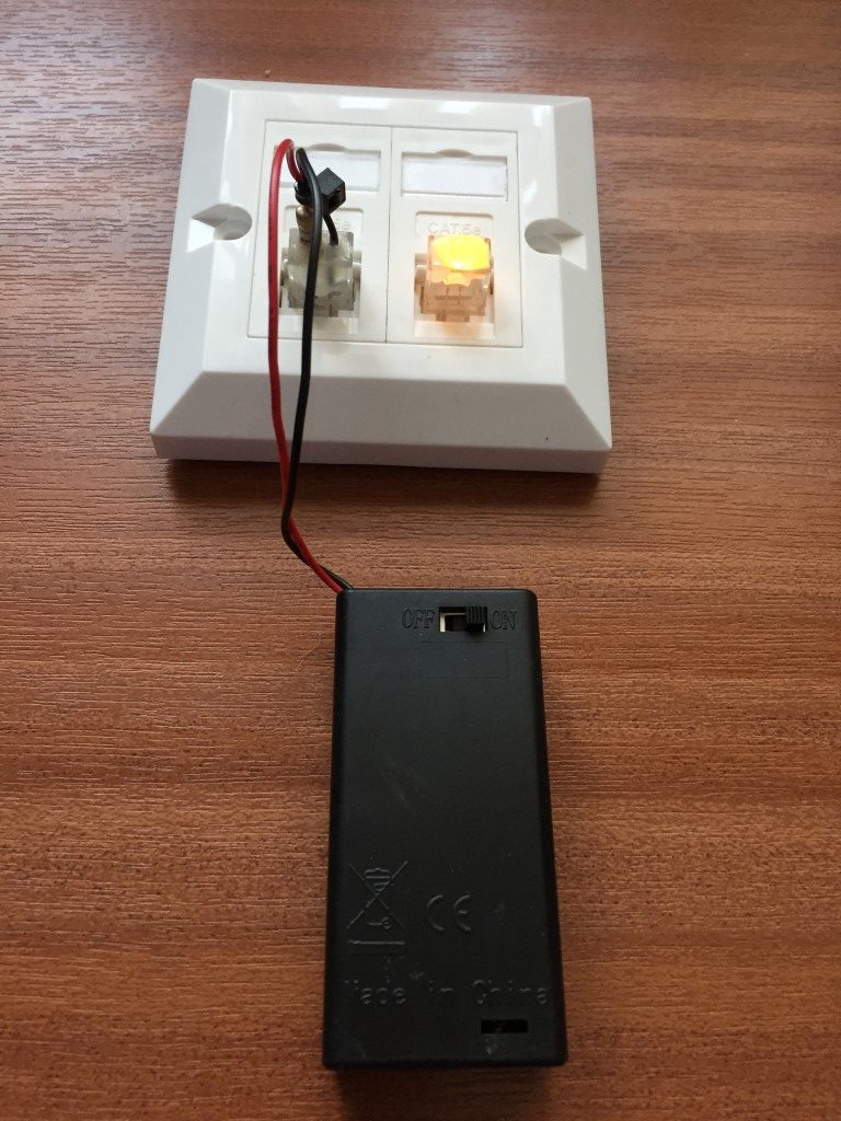
The principle is very easy, in the patch panel, RG45 plugs are inserted into each port, within the RG45 plug is an LED connected to pins 3 &6.
At the remote faceplate, a RG45 is plugged in which has power to pins 3 & 6 via a battery battery, the LED in the patch panel will now light, quickly identifing what is connected to what.
Test faceplate with pins 3 & 6 bridged across each outlet
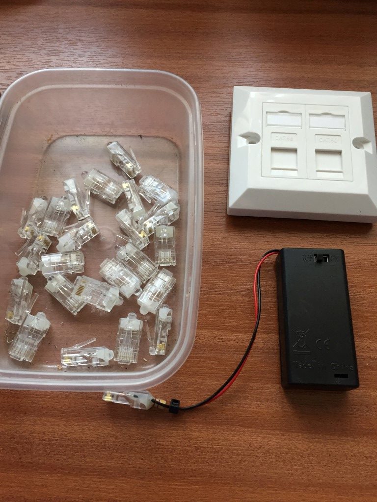
The parts were from ebay:
LEDS – 100 for £2.32
RG45 connectors – 100 for £2.95
Battery Holder – £0.99
To make the LED plug, I first marked the Cathode of the LED so I got the polarity correct when inserted into the plug.
The next step was to flatten the LED capsule so that it fits within the cable entry of the connector.
The LED is now pushed into the connector and crimped, hot glue is then used to seal the LED in place.
The battery pack is powered by 2 x AA batteries, with a current limiting resistor terminated in the plug.
I made 24 of the LED plugs as that was the number of ports on my patch panel.
After playing with a Programmable Logic Controller (PLC) to operate my radio mast, I decided to build a simulator in order to better understand the capabilities of the EASY PR-18DC-DA-R.
I wanted the simulator to have 16 inputs, either momentary or switched and the ability to import signals including an embedded 4 – 20mA current.
I had a sloped project enclosure already, so I made a dimensioned drilling template.
Once the template was stuck down, the pilot holes were drilled, template removed and holes opened to the right sizes.
The template was created in Visio and I used layers, one of the layers was for switch position drilling and alignment cross-hairs, turning that layer off (missed one in I8!), allowed me to print on self-adhesive sticky Matte White Vinyl.
Using a sharp knife, I cut though the Vinyl and started fitting the switches, buttons, Output indication LEDs and 4 – 20mA injector.
Terminal posts next.
Front panel populated.
Wiring started.
After a couple of changes, the internal wiring is completed and loomed in.
The simulator uses 24v DC, I used a small 1.5A output switched mode PSU for this, fed via a chassis fuse holder with the supply from an IEC male socket, the output from the PSU is fused separately.
PLC simulator all powered up, the program in the PLC was legacy from my mast control project, this will be overwritten by downloading revised programs from xLogicsoft software.
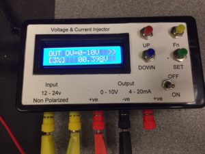
To complement the PLC simulator I bought a4-20mA Current Signal Generator 0-10V Voltage Generator Transducer Simulator for £19.00.
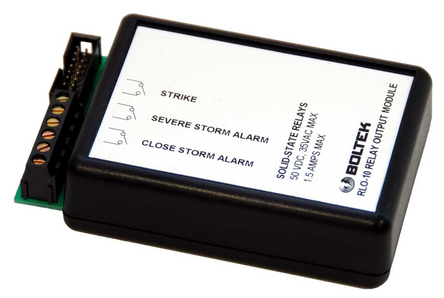
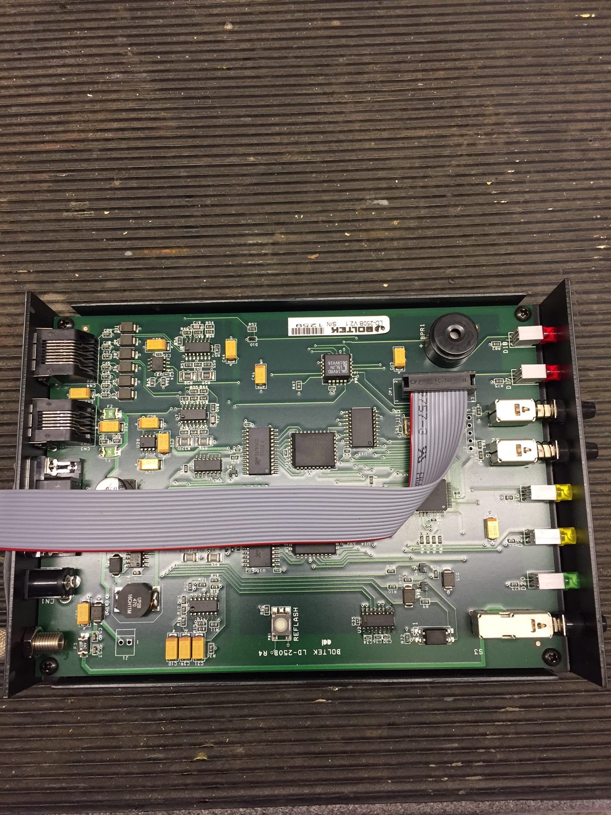
The LD-250 Lighting Detector from Boltek has an internal output for a relay interface, the manufactures units are quite expensive, so I decided to make my own.
RLO-10 Boltek Relay Interface
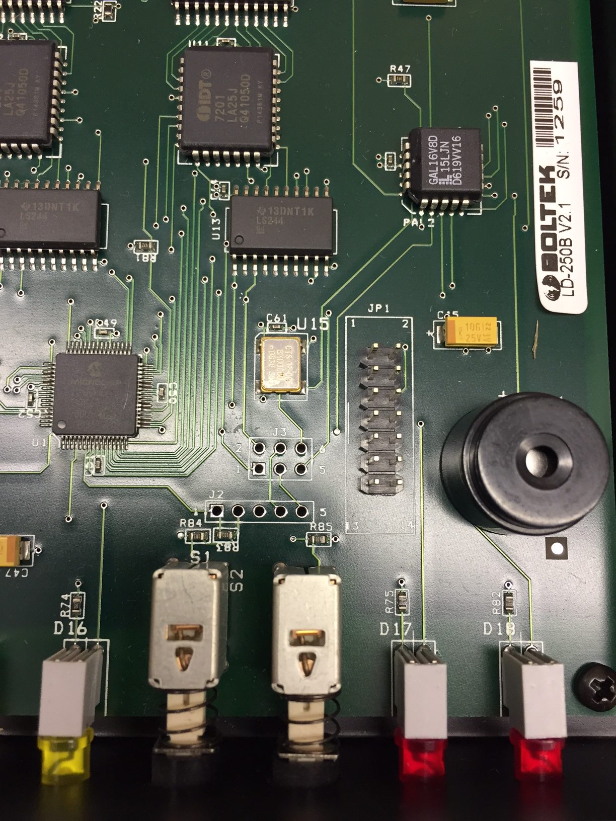
Inside the LD-250 is a 14 way header which connects via ribbon cable to the RLO-10, off eBay I bought the 14 way ribbon cable and IDC cable mount socket for £5.00.
Opening the LD-250 the header JP1 is immediately obvious:
Using my multimeter, the header output pins linked to the front panel LED’s and the operating voltage was quickly found.
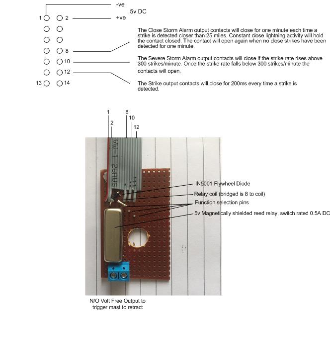
Using a spare strip of veroboard I mounted a magnetically shielded reed relay 5v, with flywheel diode across the coil, and the switched Normally Open reed output to a 2.54mm x 2 pitch connector, I also put veropins in the board so I can select which function I want the relay to operate on, should it be needed in the future.
The reed switch is used to switch 24v DC to an indicating LED and a a PLC input, the total load was measured at 21.49mA, well within the 500mA rating of the reed switch.
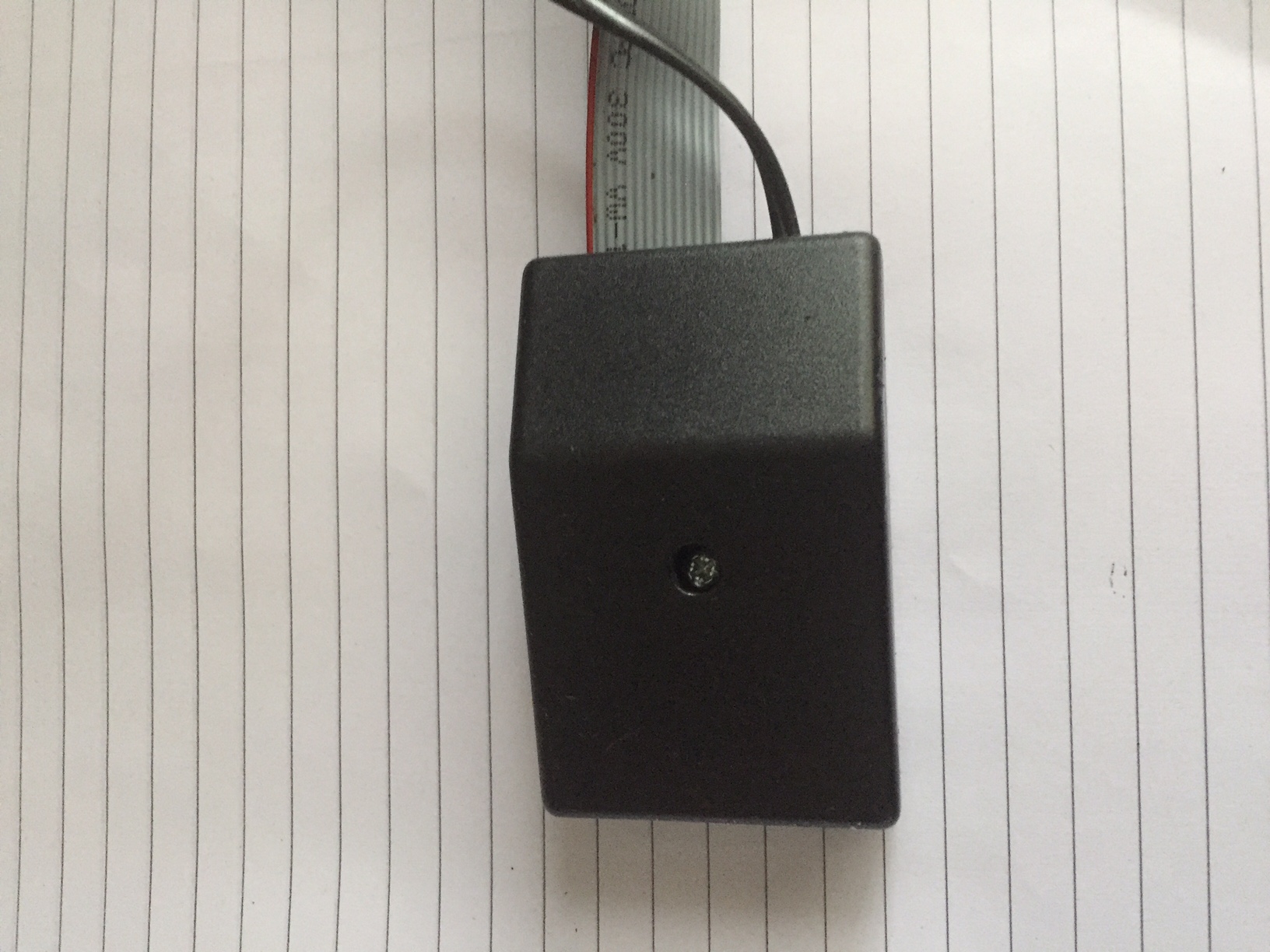
The module was placed in a small enclosure:
The ribbon cable was then plugged into JP1 inside the LD-250:
Switching on the Boltek performs a self test of the front LED’s and internal buzzer, as I have used the output from the ‘Close’ LED, the reed relay operated and the mast which was raised, automatically retracted.
All in all the project performs as expected and cost me £7 (enclosure was £2) saving me £58.95 on a factory unit.
This blog is about the roll out of Virgin Media fibre to the home in Chatteris from the civil works through to the delivery of a live service at my house and beyond.
To report insecure or damaged Virgin Media street cabinets: Call 0330 333 0444
26 October 17, Trench tarmacked and construction barriers removed.
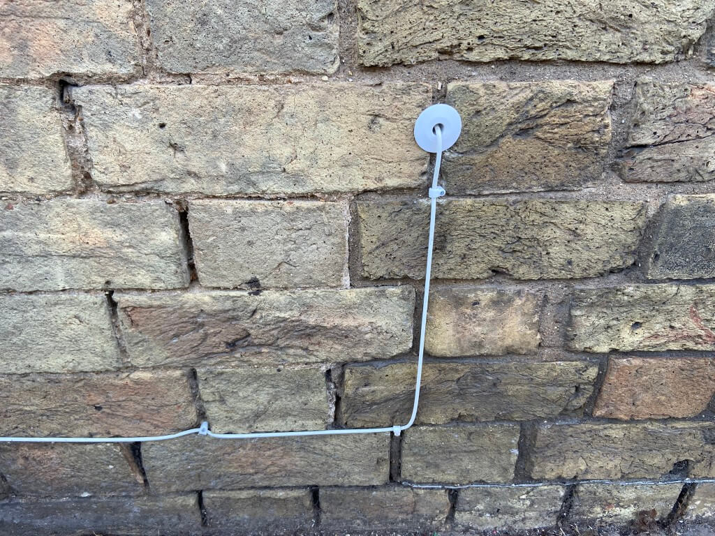
5 November 17, I buried 20mm conduit from Toby to house wall and included a draw cord.
26 Nov 18, Cabinet AF0503 made live.
1 Feb 18, Virgin Postcode Checker now shows service available in my street.
4 Feb 18, Ordered VIVID 200 package for installation on Friday 23 Feb 18 between 13:00 – 16:00. Went through to the Virgin Media shop in Peterborough looking for some form of promotion or deal to reduce costs, this didn’t happen, in fact they suggested I could save money ordering in shop as they would waive the installation and F-Secure costs, this was incorrect as the online booking information has these as free, also they wanted £25 up front, £20 activation fee and £5 which would be returned once the service was active, online it is £20 only activation, so I booked online, as an aside, if I had ordered in the shop my statutory rights to cancel is reduced from 14 to 10 days protection which you get when booking online.
11 Feb 18, received two e-mails, the first containing e-sign contract, the other was what to expect on the day of installation.
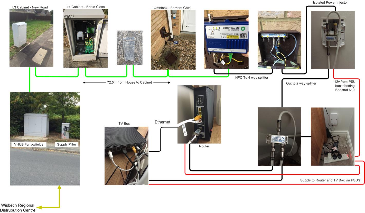
16 Feb 18, received mobile call from Callum of the Virgin Media installation team wanting to come and install a microduct from the Toby to my house, fit the Omnibox and blow the fibre from the street cabinet to the Omnibox, this is done a week in advance of the engineers on the 23 Feb, I arranged for the following day to meet them as I was 180 miles away! (this part of the process was not known to me and came out of the blue, I assumed it would be a ‘one hit’ visit).
17 Feb 18, James from the installation team rang to cancel as Callums son had a fall and was needed at home, as the install is a two man job I returned his call and rearranged for Monday 19 Feb after 16:00.
19 Feb 18, James & Callum turned up at the appointed time to install the microduct, fibre and Omnibox.
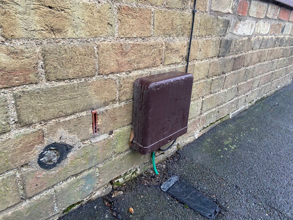
The guys first photographed a laminated sheet showing my address, date and their names next to my open Toby, once this was done they threaded a black microduct pipe from the pavement Toby through the conduit I had previously laid to the house, the brown Omnibox was fixed to the wall with 4 screws and the microduct pipe clipped into place in the Omnibox, at the Toby a coupling was installed transitioning from the green microduct to the black microduct.
Transition coupling, black microduct to house, green microduct to street cabinet.
The distance was measured using a measuring wheel from my Toby to the street cabinet (72.5 m), while the measuring was going on, compressed air was blown down the microduct from the house, this caused the yellow protective cap to be blown off the end of the green microduct in the cabinet, identifying which tube out of many, as coming from my house.
In the cabinet a ‘fibre catcher’ was fitted, at the house end the fibre cassette containing 100m of fibre was fixed on a device which enabled the fibre to be blown into the duct until it was caught by the cabinet catcher.
At the cabinet, the fibre catcher was removed and a protective sleeve was fitted over the fibre and terminated in a connection, this connection was then plugged into a breakout panel in the cabinet.
We were the first in this cabinet.
At the house end, the surplus fibre from the cassette was wrapped within the Omnibox, the house end is pre terminated, once this was done, a reading was taken of light losses (-0.13db) to check they were in an acceptable range, the reading was photographed with the laminated sheet used earlier as proof of service in advance of the technical install scheduled on Friday 23 Feb 18.
Completed Omnibox after first visit ready for the optical media converter and splitter to be fitted.
23 Feb 18, Go Live Day – Engineer Sam arrived between the allotted time of 13:00 to 18:00 to start the installation.
He was quite happy that the hole through the wall into the lounge was already in, as was the dry lining that he could hang the Isolated Power Injector on.
First job was to push a peice of HFC cable though the wall from the Omnibox and put a connector on the end, this was connected to the Isolated Power Injector (IPI) Teleste IP1-G1)), which is mounted within an enclosure on the lounge wall (the screw holes of the enclosure and backplate fit a standard dry lining box), a short length of HFC cable from this goes to a 12v plug in PSU in order to back feed the external optical media converter with power.
The bottom IPI output is connected to a 2 way splitter (Technetix ESX-02), one leg goes to the router (a 3db attenuator was installed to balance the system), the other leg to the TV box.
As the TV box, Router and Optical media converter require power, three 240v sockets are required.
In the Omnibox, the HFC cable was terminated, and plugged into a DC passing port of the 4 way splitter (Amphenol Model ABS104TP), from the splitter this is plugged into the Vector Boostral 610 optical media converters output.
Once the external works was completed, the router and TV box were powered up and an Ethernet cable from the router to TV box was plugged in. The hardware went through three re-boots and software updates and I was good to go.
24 Feb 18, Netflix is suffering lip sync issues when viewed through the VM TV Box, also download speeds vary from 210Mb to 38Mb (wireless tests), it’s early days, so I hopefully this will stabilize soon.
25 Feb 18, Speed test using direct cabled connection to Virgin Media router (200Mb service ordered) :
25 Feb 18 @ 14.11
2 Mar 18, TalkTalk, my existing provider reduced my package ‘Fibre Large’ which is Fibre To The Cabinet’ (FTTC) by £26:25, on knowing I was thinking about leaving for Virgin Media, they did this by moving me to the ‘Faster Fibre Plan’.
I get the same package as before (TV, broadband and phone landline including line rental) for £31.75 per month, the download and upload speeds I’m getting are more than enough for my needs even when all the kids are home battering the broadband, also I keep my landline, Virgin Media have not yet enabled VOIP on the router which was another factor for me.
I called Virgin Media to cancel my arrangement (within the 14 day ‘cooling off’ period), they obviously asked why and I mentioned the main reason was cost and as an aside, that my wireless speeds were faster with TalkTalk rather than Virgin Media.
Perplexed by this, he transferred me to technical in a foreign land and they remotely checked the line and rebooted the router, then asked me to perform a router reset using a paperclip, which I did whilst they were on the phone. They assured me everything was working properly and I did a wireless speedtest and managed 136Mb download.
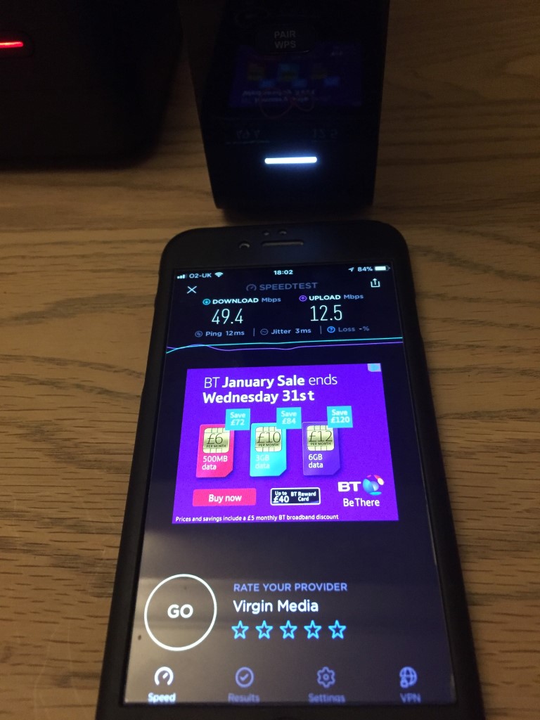
Checking later I took the following images of speed:
Download 49.4Mb, Upload 12.5 Mb from Virgin Media
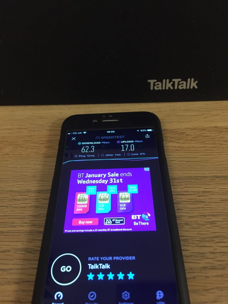
Download 62.3Mb, Upload 17Mb from TalkTalk on 5GHz
The above results used OOKLA Speedtest on an iPhone 6, as the SSID on the Virgin Media router is the same for 2.4GHz and 5GHz I didn’t know which Wi-Fi band I was measuring, I was however, the only device was connected to it.
For balance I ran another TalkTalk test at 2.4GHz, and the readings came out at Download 41.7Mb, Upload 16.8Mb which wasn’t too shabby, especially as 7 wireless devices were connected.
I also ran a directly ethernet connected Virgin Media router test later with a laptop at 20:00hrs 2 March 18, and managed a download speed of 76.17Mb and upload of 10.3Mb, not brilliant for an upto 200Mb service which I was assured was working as it should.
The upshot is that I staying with TalkTalk meaning that I reluctantly terminated my arrangement with Virgin Media effective from 3 March 18.
8 Mar 18, Disconnected my Virgin Media as per the instructions which came in my returns packaging and boxed up the following way as requested:
Router;
TV box;
Remote control;
Two power supplies;
Leads for the above PSU’s;
Splitter and three CATV cables.
This was then taken to my local ‘Click & Collect’ store and it was winging it way back to Virgin Media at nill cost to me.
14 Mar 18, Text from VM to say the kit has been received and any charge for kit that might have been applied to my account will be credited, also received an e-mail:
21 Mar 18, Received my first and last Virgin Media bill, this covers the week I had the service and the activation charge, total payable – £36.67.
30 Mar 18, Checking my bank statements and no money has been taken by Virgin Media so I cancelled the Direct Debit to them.
1 Apr 18, Received e-mail from Virgin Media thanking me for joining them and asking me to complete a short survey which I did even though I’m no longer a customer.
4 Apr 18, Virgin Media activity showed on my bank statement ( – £36.76 then +£36.67), contacted VM and they said I do not have to pay anything as I cancelled within 14 days.
11 Apr 18, Text from Virgin Media to call 0800 052 2630 in order to clear my outstanding balance, talked to Kirsten and she saw the error that cancelling within 14 days shouldn’t have triggered a bill, so she added a small credit to my account in order to cancel the debt on the system.
25 May 18, Received letter from Virgin regarding GDPR.
Hybrid Fibre-Coaxial cable and below that a fibre optic connector
Phased civils started in June 2017 and by 4 January 2018 first subscriber activated.
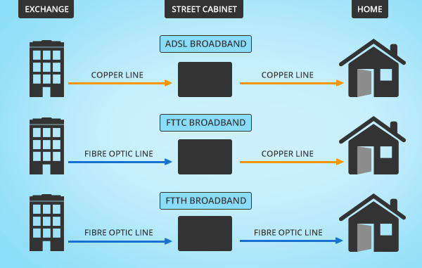
I currently use TalkTalk Fibre to the Cabinet, this the same as BT Infinity, SKY, Plusnet etc, this means a fibre optic cable is brought from the local exchange to a street cabinet, from this the existing telephone copper cable is used for broadband and phone, depending how close you are to the cabinet will determine how fast your broadband is, in may case, I get a maximum speed of 62.79Mbps download, 17.34Mbps Upload and a Ping time of 17.34ms which is probably the best I can get (using Speedtest 15/11/17 @ 18:00).
Diagram showing how Fibre To The Home (FTTH) is just that.
I was delighted when I saw that the Virgin Media cable enabling works was scheduled for installation via Roadworks.org, bringing up to 300Mb speeds to Chatteris, this will give people an option, rather than be tied to telephone line provided services, so I thought I’d start this blog.
This speed test was done on the 25 Feb 18 @ 14.14 by directly connecting a cable to the TalkTalk router to compare FTTC with Virgin Media FTTH:
Not to shabby performance for over copper wires.
Infrastructure Process
The infrastructure in my area was due to start on 4 August 17, expecting to last until the 14 August and I registered my interest in advance using Cable My Street.
My roads infrastructure work started on the 23 October 18 and was carried out very swiftly and with minimal mess considering the civil work required, the works was undertaken during school holidays to minimise any disruption, the crew were respectful of any request to get on and off the drive, also in my case I wanted the ‘Toby’ to be in a particular position, this wasn’t a problem and on the pictures below you can see the original point marking has been crossed out, and the new position marked as a red box.
VM installing my Toby
Time lapse video of Virgin Media installing FTTH infrastructure.
Details on how the Virgin Media infrastructure is installed (for developers but a great resource) is HERE (large file) and a general guide used for another town scheme is HERE.
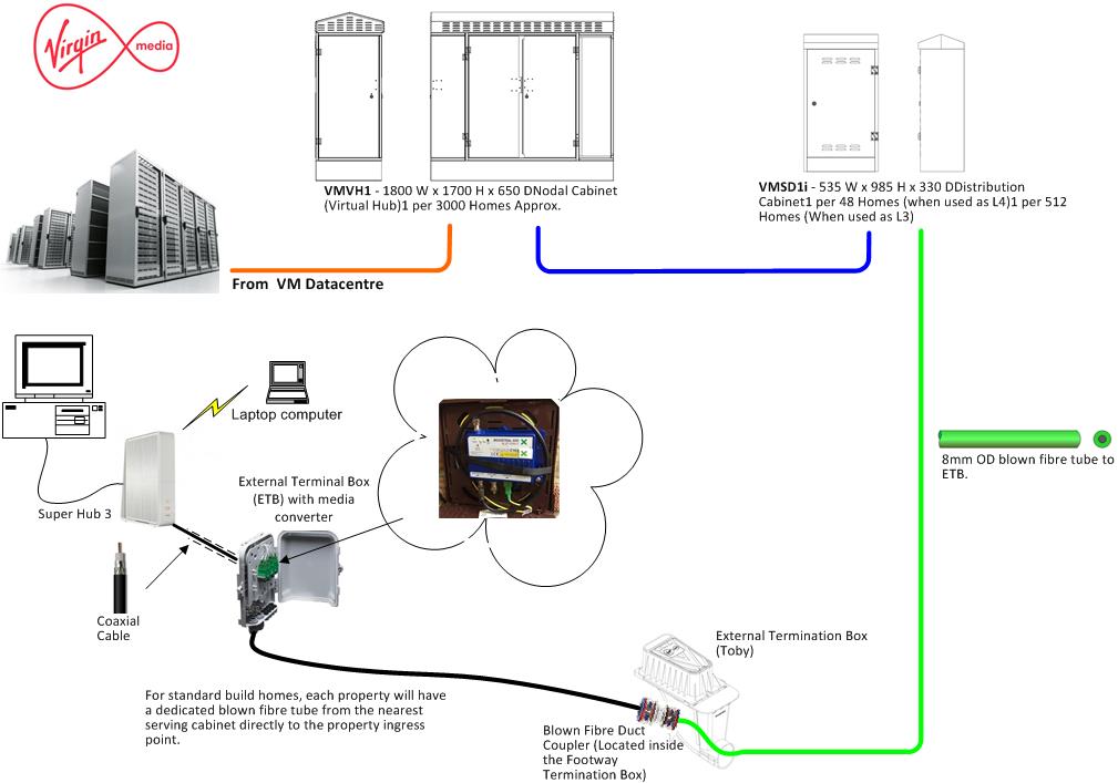
The system we are getting from Virgin uses RF over Glass, with the infrastructure being installed by John Henry Group. This comprises of a fibre optic cable laid in a trench which is blown through a microduct tube from the nearest cabinet to the home after your order is placed.
I’ve included a YouTube video by EJC to show hows its done when the cameras are rolling.
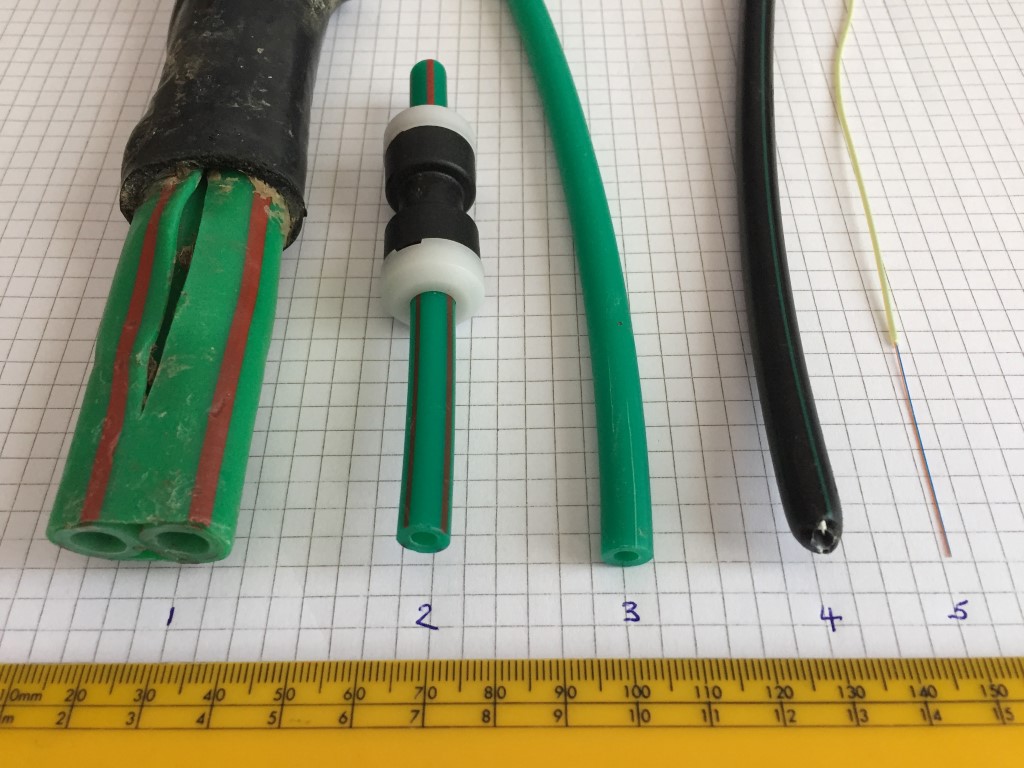
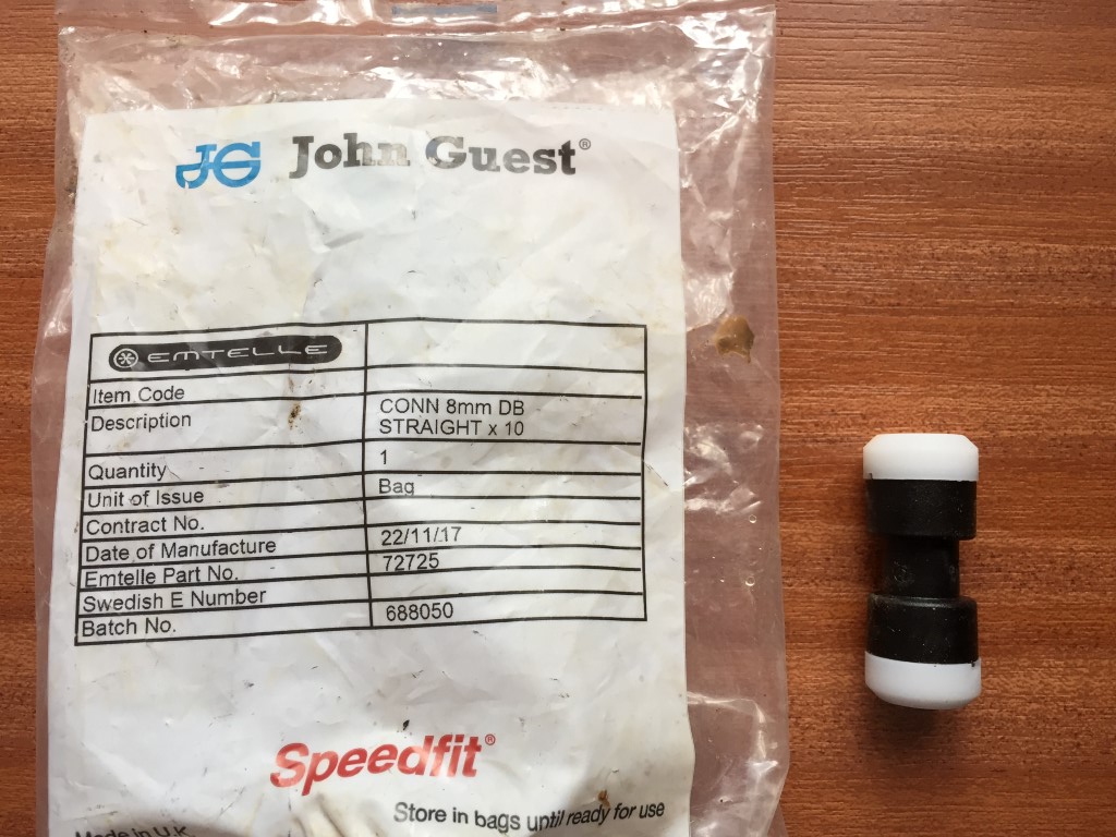
Microbore tube showing fibre optic cable
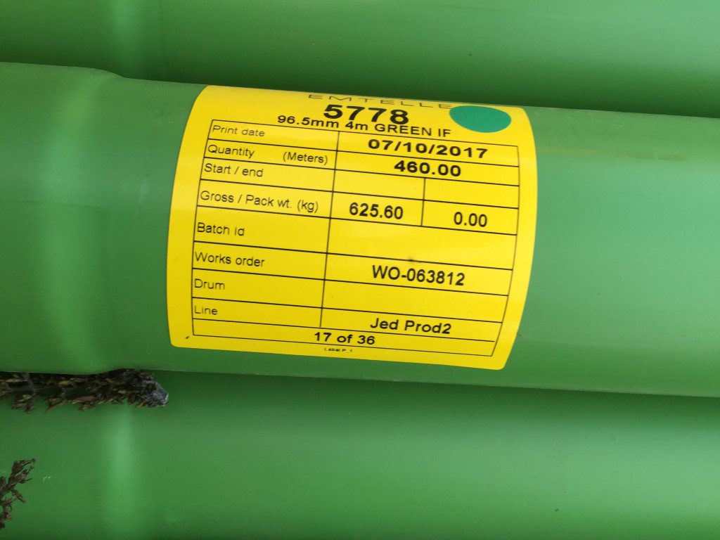
The wrapped Red and Green double tube is installed from the VMVH1 hub cabinets to the Level 3 (L3) street cabinets via solid ducts. Each tube has an Outside Diameter (OD) is 12mm one tube is used to transport 24 core fibre optic cable, the other bore is spare.
Duct for transporting double Green/Red stripped microduct.
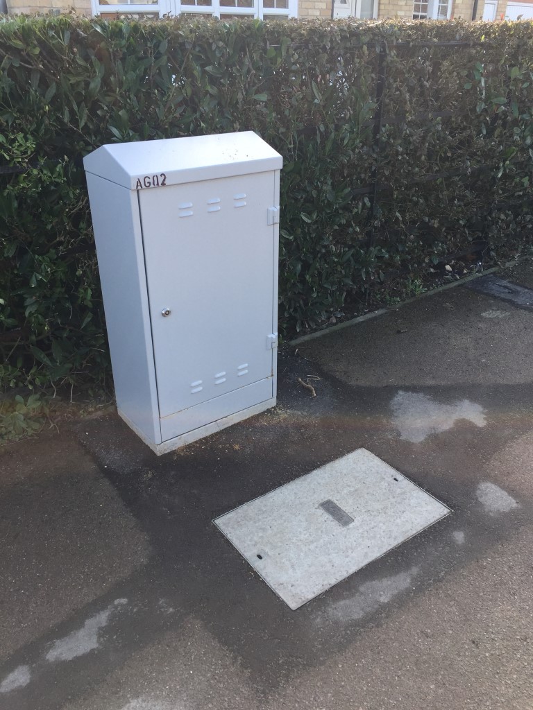
2. The single Red and Green has an OD of 8mm and carries 12 core fibre optic cable from the L3 cabinet to the Level 4 (L4) distribution board. The L3 cabinets are identified by having only two letter and two numbers stenciled on them.
Level 3 cabinet in St Martins Road
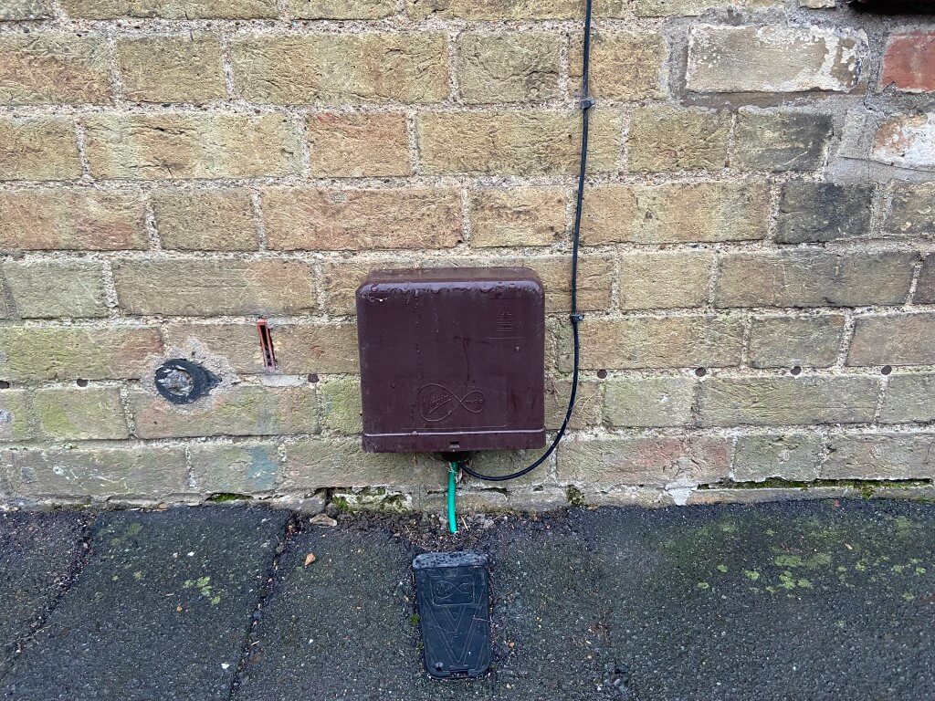
3. The Green microbore is 8mm OD and is ran from the L4 cabinet to each ‘Toby’ outside the property.
4. Black microbore is the same dimensions as the Green microbore and is used from the Toby at the pavement to the house Omnibox.
5. 1.1mm diameter single mode fibre optical cable containing two fibres, I stripped the fibre back in the above picture, from the factory the fibre is pre-terminated.
Connection method used in the street cabinet after the fibre has been blown in.
8mm straight couplings used to connect microducts.
The image below shows the microduct couplings in use within a pavement trench. Top picture taken at the junction of Dock Road and Bridges Street, bottom picture taken by the library shows a larger 12mm OD striped microduct.
Larger size microduct and coupling, (possibly for a multicore fibre, rather than a single fibre?).
The marker tape which is put over the buried Virgin Media infrastructure and serves two purposes, the first is to allow detection using a Cable Avoidance Tool (CAT), the marker tape has two metal wires bonded to it, so the route of the tape can be found and traced from the surface without excavation, the second purpose is to warn that you are about to unearth or hit cables should you be digging.
Nice swerve around 🙂
VMSDI Level 4 Open Cabinet Picture – undergoing second-fix.
VMSD1i – 535 W x 985 H x 330 D Distribution Cabinet 1 per 48 Homes (when used as L4)1 per 512 Homes (When used as L3) – Cabinet found locked in the open position 5/11/17
Click Map Pin on the corner of Ash Grove and High Street for more images of cabinet AF0113.
Great guy second fixing AG01 which is a Level 3 cabinet.
One of the towns two VMVH1 Nodal Cabinets
Newly installed VMVH1 – 1800 W x 1700 H x 650 D Nodal Cabinet (Virtual Hub)1 per 3000 Homes Approx. The yellow temporary cover was used to protect the hole before the VMVH1 cabinet was installed.
Inside VMVH1 supply pillar
Permission asked of road workers to take pictures, cabinet unlocked and open 18 Nov 17
Within the distribution board above is a smart RCD from Tii-Tech which is rather clever as it performs regular operational self tests to avoid the need for a person to visit the cabinet to do them.
End of Line Termination Boxes
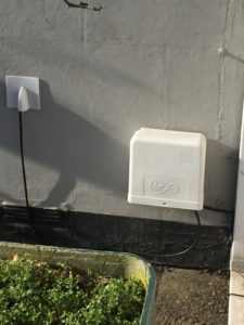
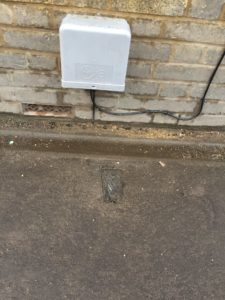
From the street termination box, a microduct coupling is used to extend the duct from the street cabinet to your outside wall, the fibre once blown through is connected to a media converter within the externally mounted Omnibox
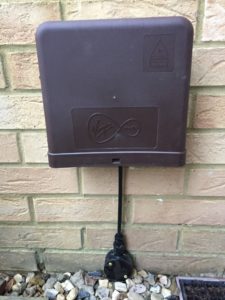
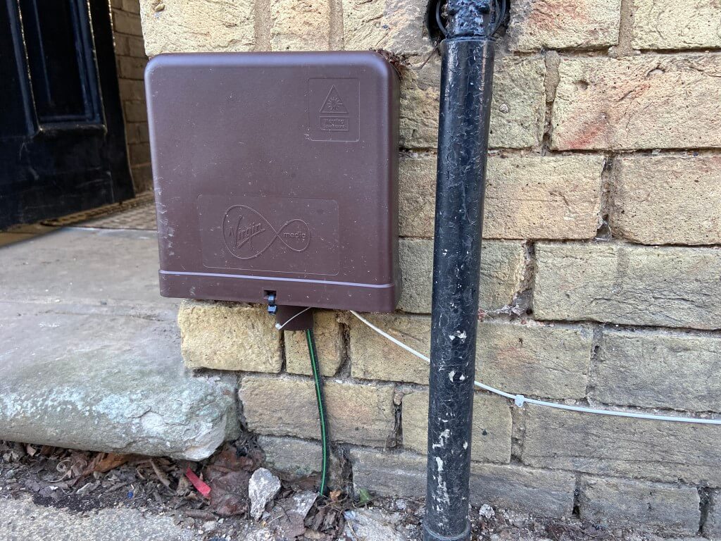
Showing the three different colours of Onmibox used in Chatteris, the last one is mine.
The media converter changes the fibres optical pulses of light into electrical data which a coaxial cable then takes to the Super Hub 3 Router and connectivity to the internet.
Cassette of single mode fibre, pre-terminated, up to 500m in increments of 25m are used dedpending on the distance from home to cabinet (25m, 50m, 75m, 100m, 125m, 150,m 300m & 500m).
This configuration will give data transfer speeds of up to 300Mbps, a basic outline of how it connects together is below, the VM Datacentre is in Wisbech and Chatteris is fed by a direct fiber from their:
Data centre to house
In advance of Virgin installing the infrastructure in the street I have put a conduit through the wall into a dry lining box with a blank please and installed a length of 20mm flexible conduit from the pavement Toby to the house wall, bit premature, but hey ho 🙂
Links to latest and archived Planning Permissions for Chatteris containing Virgin Media infrastructure works (remedial works have been excluded) :
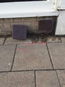
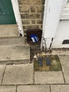
Remedial works undertaken to the ducting infrastructure, pavement trenching made good and raised Toby’s lowered.
Update -11 Jan 2021
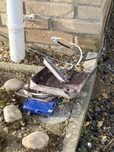
Damage to kit and check out how deep that fiber is as it crosses the lawn, so easy to damage!
The depth of the fiber pipe is about 40mm, so easy to damage if doing lawn maintenance!
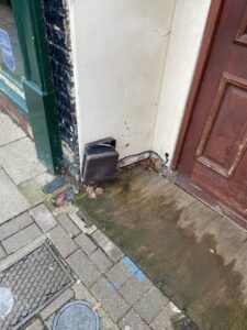
Unfortunately the Omnibox is easily damaged/abused.
Update 1 July 2021
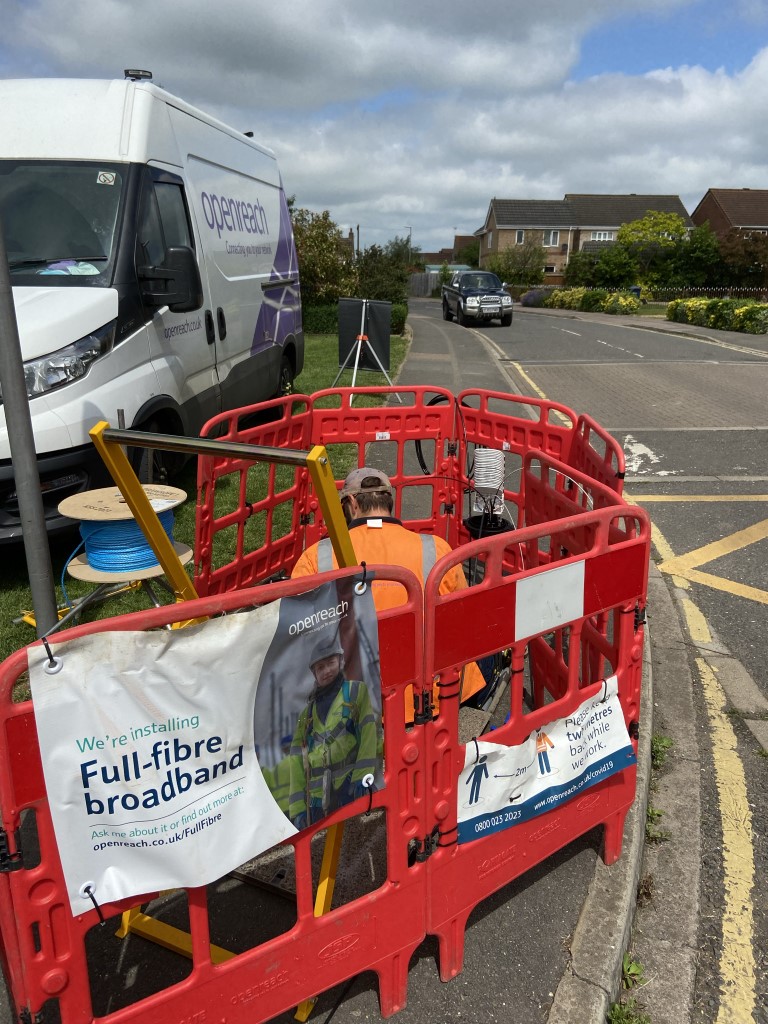
Openreach are installing the infrastructure for Ultra Fast Broadband, Virgin no longer has the monopoly on decent speeds which can only be good for the consumer.
How things change since 2018 when Virgin Media went live in Chatteris, the choice of Fibre to the Premises Ultrafast broadband Internet Service Providers is now a lot larger using Openreach fibre infrstructure.
The new kid on the block, (2023), is Netomnia with there own dedicated infrastructure and competitive pricing is displacing existing Virgin Media customers:
Who knows what’s next?
Update 2024 – Nexfibre
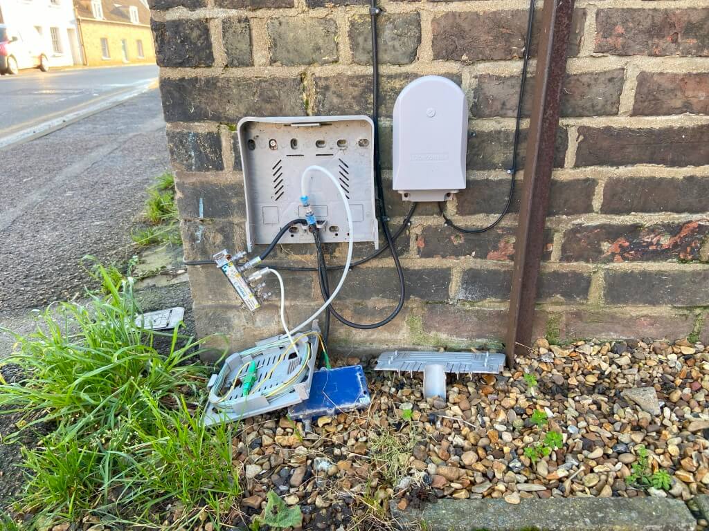
Virgin Media O2 are modifying their home network connection by removing the co-ax cable element and media converter active component, (blue box in the above picture), for fiber directly into the house. Due to the removal of the media converter, the external box can be a lower profile design.
The modification will now enable comparable performance with other internet providers.
One thing I did notice on my walkabouts is the installer appears to have removed the outer UV protective fibre sheath and the cable clipping looks to have bend the fibre outside its minimum radius on this installation.
Not sure if the white inner is UV stabilized, but I thought it an odd thing to do and generally looks a Friday job.
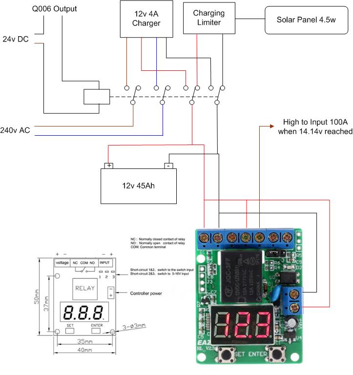
Link back to Radio Mast Automation – HERE where the EASY RL-V23 unit can just be seen attached to the lid of the mast controller.
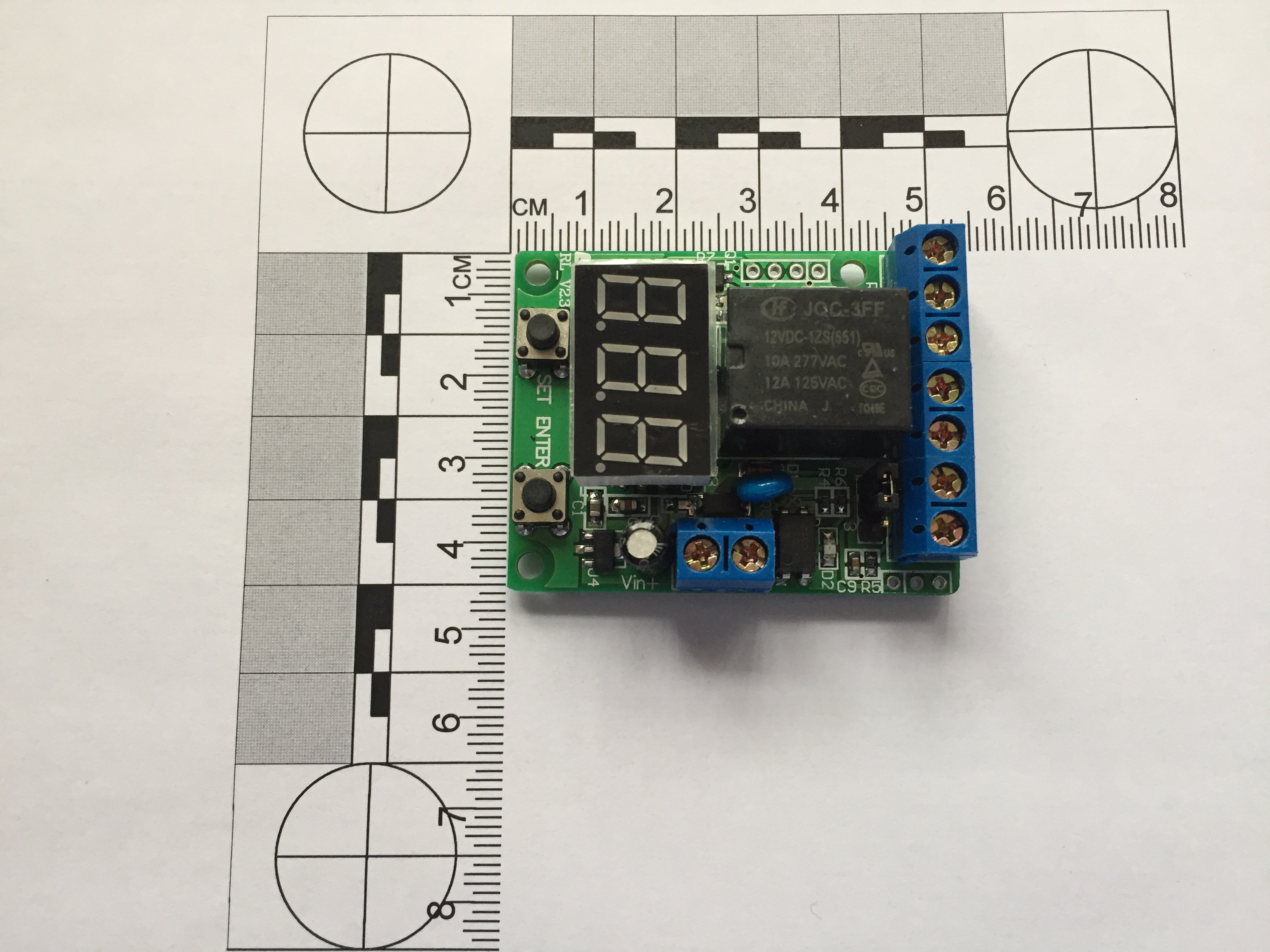
EASY Voltage Unit
The above module was from eBay and advertised as a ’12V Voltage Control /Delay Switch /OverVoltage /Under Voltage Protection Module’ for £4.92.
This unit is incredibly versatile, and I’ve included the operating instructions in the blog.
I have used this module to monitor the charging voltage of a battery, once the voltage has reached a pre-set value, an output will trigger to stop the charger.
Operating modes:
P-1: Timer ( 1-999 S / 1-999 Min)
P-2: Delay timer ( 1-999 S / 1-999 Min)
P-3: Voltage control relay ( control the load on/off)
P-4: Voltage control Timer- A (release first)
P-5: Voltage control Timer- B (close first)
P-6: Voltage range control relay
P-7: Voltage range control Timer
P-8: Set display off
Timing Range: 0-999 seconds or 0-999 minutes (0.1s-999s optional)
Voltmeter display range: DC 0-99.9 V
Voltage detection error: ± 0.1V
Operating Power: DC10~16V (5V,24V optional)
Relay parameters:
Coil Voltage: DC 12V (5V,24V optional)
A set of conversion (normally open and normally closed)
Contact load: 10A/277V AC or 10A/30V DC
Contact resistance: ≤ 100mΩ (1A 6VDC)
Mechanical durability: 10 millions
Electricity durability: > 100,000 (10A-250VAC)
Operating Temperature: -40 ~ 85℃
External signal input: (5~ 12V) or passive switch (9 levels delay time can be set)
Timer mode can set the relay contact close and release time, the implementation of a single timing loop
In voltage control mode, can preset upper and lower voltage values limits
Set display shut, the minimum current values are 6mA/12V (delay released)
The pre-set parameters can be saved after power off.
2 Operating modes:
Connect to power, LED digital tube displays words “E-A-Z-Y-t” in turn, system enter into the selection state, the initial mode selection is displayed as “P-0”, press the “SET” button to select “P-1~P-8” mode, press “ENTER” to enter the corresponding mode.while any mode running, press the “ENTER” button for 3 seconds, system will return to the mode selection state.
Press the “SET” and “ENTER” button to connect the power, the controller will be restored to factory settings.
2.1 Timer mode (P-1)
Press the “SET” button to select “P-1”, controller system will enter into the timer mode.
“P-1”/ “P-2”: 1-999 seconds /minute can be set.
Cyclic run:
In the timer mode, the user can set the relay’s close time T1 and the release time T2,such as setting T1 for 3 seconds, T2 for 7 seconds, the relay will be closed for three seconds then release for 7 seconds, cyclic run.
User also can set cyclic times.
When you have set the values of the T1 and T2 , the system saved the settings, the next time system will be loaded automatically T1 time to wait running.
Timer:
If you set T1 with a specified time, set T2 (release time) with 0, the relay will stop after the timer run T1 time, no longer running, it can be used as a timer, with running time end, the normally open contact of relay release, then press the “ENTER” button, the system re-start the timer for T1 time.
In timer state, you can use external switch or pulse signal input Interface on controller to start the timer (trigger).
Timer setting steps:
1) For the first time of set , select “P-1” time relay mode, LED digital tube display” 000 “;
2) Press the “SET” button, system will enter into the T1 time values settings first, the digital LED that wait for set flashing with 1Hz frequency, press “ENTER” to select the number of values, press the “SET” button for three times to enter the T2 time values settings, and cyclic times, press the “SET” button to exit the set state, the system waits to press “ENTER” button to start running.
3) In the time setting state ,time values’ unit can be switched to minutes unit or second unit, press the “SET” button to enter the time set by state (set LED digital tube flashing) ,at this time Press the “SET” button for 3 seconds to release ,the LED digital tube will light the right decimal points, it means that timing values with minutes unit, if the decimal point dose not light, it means that timing values with seconds unit.
4) After setting is completed, press the “SET” button to exit the setting state, press “ENTER” to start timing, if timing values is set with second unit, seconds values will display with countdown form. If timing values is set with minute unit, the right decimal point flashing with 1Hz frequency, means the countdown is running. While timer is running, the normally open contact of relay connected, the normally closed contact of relay disconnect, press the “ENTER” to halt run, press the “ENTER” for three seconds to return mode selection state “P-0”.
2.2 Delay timer (P-2)
The Setting method of “P- 2” is the same as “P- 1”, in the mode of “P-2”, the relay will first execute release of T1 time then closed with T2 time.
2.3 Voltage control relay mode (P-3)
In mode selection state(“P-0”), press the “SET” button to select “P-3”, then press the “ENTER” to enter the voltage comparison control mode, the controller will detect voltage from “VOL” Interface and display values (DC 0-99.9V),it also can be used as a DC voltmeter ,the default initial run state relay contact is closed (normally closed contact is disconnected, normally open switch on), press the “SET “button to set the three bit values, the LED digital tube is set to flashing with1Hz frequency, first to be set upper limit voltage values , press the “SET” button three times, lower limit values of voltage to be set,press the “ENTER” button to increase the number of values, the lower limit voltage can not exceeds the upper limit, press the “SET” button to make digital tube is no longer flashing, this time system enter into voltage control mode , the controller detects DC voltage from external input Interface , when voltage detection exceed the upper limit of the pre-set, the relay close (normally open contact connect ,normally closed disconnect), until the voltage drops below the lower limit pre-set, the relay will release (normally closed contact connect , normally open contact disconnect).
In voltage control condition, press the “SET” button for three seconds then release the button, the contact of relay state will be reversed. such as: the relay close when detect voltage below the lower limit voltage.
If the pre-set voltage upper and lower limits set to the same, such as 12.0V, when controller detect volts at 12.0 fluctuations may cause the relay contact frequent action, we recommend to set the voltage to maintain the difference between the upper and lower limits.
Note: The detection voltage terminal must connected reliable, have not loose wiring around the circuit board insulation ,may lead to the induced voltage detection values is not accurate.
2.4 Voltage control Timer mode (P-4 / P-5)
“P-4” or “P-5” mode is composed of “P-1” and “P-3” or “P-2” and “P-3”.When the system switched to “P-4” from “P-1”or“P-2”,it will enter the voltage control timer mode, the controller will detect voltage from “VOL” Interface ,when detect voltage exceed the upper limit of the pre-set voltage, the timer will start , until the volts drops below the lower limit pre-set , the timer stop.
If you set time in “P-1” mode previous, then enter the “P-4” mode , the relay will close with timer first ,then release, If you set time in “P-2” mode previous, then enter the “P-4” mode ,the relay release with timing then closed.
The difference between “P-4” and “P-5” is the relay’s Initial state, “P-4” mode relay release first, but “P-5” mode relay close first.
Press the button of “SET” last for 3 seconds, the timer will start in the case of the voltage is below the lower limit. the setting method of limit pre-set voltage, please refer to section 2.3.
For example:
(1) In P-2 mode , set T1 005, T2 000, then enter P-4 mode , voltage detection exceed the upper limit of the pre-set the relay will close after 5 seconds, voltage drops below the lower limit pre-set the relay release Immediately.
(2) In P-1 mode , set T1 005, T2 000, then enter P-5 mode, voltage below the lower limit pre-set the relay close immediately, voltage detection exceed the upper limit of the pre-set the relay will release after delay 5 seconds.
Voltage control logic can be reversed with press SET key for 3 seconds.
2.5 Voltage range control relay (P-6)
If the voltage controller detects exceed the upper limit of the pre-set voltage, or the voltage drops below the lower limit pre-set voltage, the relay will close, otherwise the relay release between upper limit and lower limit range. Press the button of “SET” last for 3 seconds, the relay reversed. The relay will close between upper limit and lower limit.
2.6 Voltage range control Timer (P-7)
If the voltage controller detects exceed the upper limit of the pre-set voltage, or the voltage drops below the lower limit pre-set voltage, the relay will run follow time relay mode that has been set in P-1 or P-1 mode previous.
When voltage values between the upper limit and lower limit range, press SET key for 3 seconds, relay reversed between close and release (ON/OFF).
For example:
In P-1 mode, set T1 005, T2 000, then enter P-7 mode, set relay close between upper limit and lower limit range. When voltage below lower limit or exceed upper limit, the relay will release after 5 seconds.
2.7 Set display shut (P-8)
The display shows “d-0” means keep bright, you can press the button of “SET” set 0-9 minutes for display shut.
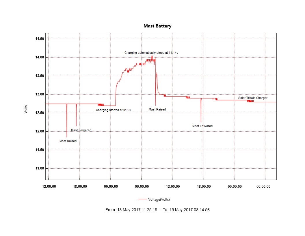
Graph showing operation of raise and lower including the automatic charging cycle.
A blog about stuff that interests me or I have done.
We use cookies on our website to give you the most relevant experience by remembering your preferences and repeat visits. By clicking “Accept All”, you consent to the use of ALL the cookies. However, you may visit "Cookie Settings" to provide a controlled consent.
This website uses cookies to improve your experience while you navigate through the website. Out of these, the cookies that are categorized as necessary are stored on your browser as they are essential for the working of basic functionalities of the website. We also use third-party cookies that help us analyze and understand how you use this website. These cookies will be stored in your browser only with your consent. You also have the option to opt-out of these cookies. But opting out of some of these cookies may affect your browsing experience.
Necessary cookies are absolutely essential for the website to function properly. These cookies ensure basic functionalities and security features of the website, anonymously.
Cookie
Duration
Description
_GRECAPTCHA
5 months 27 days
This cookie is set by the Google recaptcha service to identify bots to protect the website against malicious spam attacks.
cookielawinfo-checkbox-advertisement
1 year
Set by the GDPR Cookie Consent plugin, this cookie is used to record the user consent for the cookies in the "Advertisement" category .
cookielawinfo-checkbox-analytics
11 months
This cookie is set by GDPR Cookie Consent plugin. The cookie is used to store the user consent for the cookies in the category "Analytics".
cookielawinfo-checkbox-functional
11 months
The cookie is set by GDPR cookie consent to record the user consent for the cookies in the category "Functional".
cookielawinfo-checkbox-necessary
11 months
This cookie is set by GDPR Cookie Consent plugin. The cookies is used to store the user consent for the cookies in the category "Necessary".
cookielawinfo-checkbox-others
11 months
This cookie is set by GDPR Cookie Consent plugin. The cookie is used to store the user consent for the cookies in the category "Other.
cookielawinfo-checkbox-performance
11 months
This cookie is set by GDPR Cookie Consent plugin. The cookie is used to store the user consent for the cookies in the category "Performance".
CookieLawInfoConsent
1 year
Records the default button state of the corresponding category & the status of CCPA. It works only in coordination with the primary cookie.
PHPSESSID
session
This cookie is native to PHP applications. The cookie is used to store and identify a users' unique session ID for the purpose of managing user session on the website. The cookie is a session cookies and is deleted when all the browser windows are closed.
viewed_cookie_policy
11 months
The cookie is set by the GDPR Cookie Consent plugin and is used to store whether or not user has consented to the use of cookies. It does not store any personal data.
Functional cookies help to perform certain functionalities like sharing the content of the website on social media platforms, collect feedbacks, and other third-party features.
Performance cookies are used to understand and analyze the key performance indexes of the website which helps in delivering a better user experience for the visitors.
Analytical cookies are used to understand how visitors interact with the website. These cookies help provide information on metrics the number of visitors, bounce rate, traffic source, etc.
Cookie
Duration
Description
_ga
2 years
The _ga cookie, installed by Google Analytics, calculates visitor, session and campaign data and also keeps track of site usage for the site's analytics report. The cookie stores information anonymously and assigns a randomly generated number to recognize unique visitors.
_ga_92TJCVGJP2
2 years
This cookie is installed by Google Analytics.
_gat_gtag_UA_48800884_1
1 minute
Set by Google to distinguish users.
_gid
1 day
Installed by Google Analytics, _gid cookie stores information on how visitors use a website, while also creating an analytics report of the website's performance. Some of the data that are collected include the number of visitors, their source, and the pages they visit anonymously.
CONSENT
2 years
YouTube sets this cookie via embedded youtube-videos and registers anonymous statistical data.
is_unique
5 years
StatCounter sets this cookie to determine whether a user is a first-time or a returning visitor and to estimate the accumulated unique visits per site.
is_visitor_unique
2 years
StatCounter sets this cookie to determine whether a user is a first-time or a returning visitor.
sc_is_visitor_unique
2 years
StatCounter sets this cookie to determine whether a user is a first-time or a returning visitor.
Advertisement cookies are used to provide visitors with relevant ads and marketing campaigns. These cookies track visitors across websites and collect information to provide customized ads.
Cookie
Duration
Description
NID
6 months
NID cookie, set by Google, is used for advertising purposes; to limit the number of times the user sees an ad, to mute unwanted ads, and to measure the effectiveness of ads.
VISITOR_INFO1_LIVE
past
A cookie set by YouTube to measure bandwidth that determines whether the user gets the new or old player interface.
YSC
session
YSC cookie is set by Youtube and is used to track the views of embedded videos on Youtube pages.
yt-remote-connected-devices
never
YouTube sets this cookie to store the video preferences of the user using embedded YouTube video.
yt-remote-device-id
never
YouTube sets this cookie to store the video preferences of the user using embedded YouTube video.
yt.innertube::nextId
never
This cookie, set by YouTube, registers a unique ID to store data on what videos from YouTube the user has seen.
yt.innertube::requests
never
This cookie, set by YouTube, registers a unique ID to store data on what videos from YouTube the user has seen.


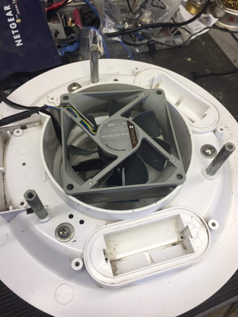
 The finished fan after the seal is applied and checking that the fan is sucking, rather than blowing: