Updated 10 November 2025
Link to mobile inlet protection version
We recently had a 4 hour power outage due to a blown street joint and found out I could now hardly lift my existing generator, so it was time for a rethink.
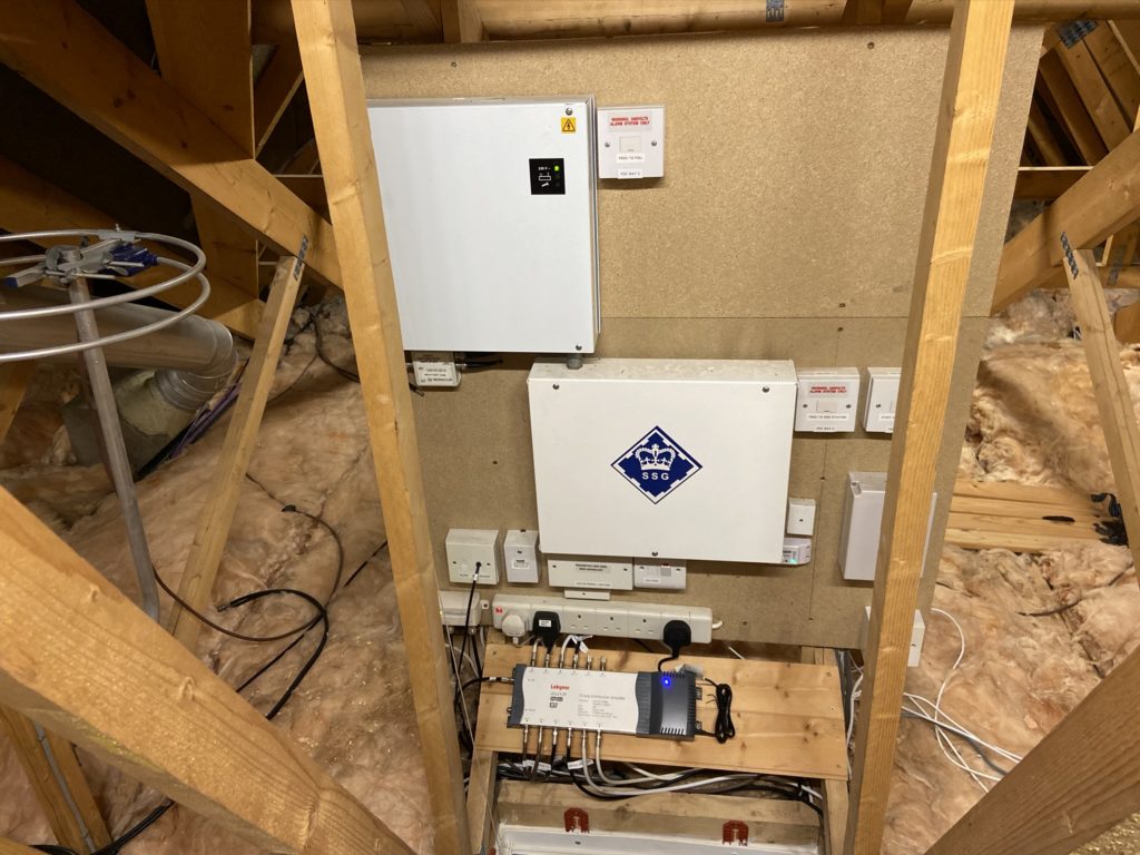
My previous blog covers the internal transfer switch enabling my consumer unit to be safely switched from utility power to local generation, that bit of the system has not been altered.
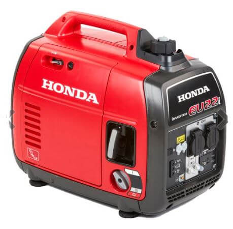
This blog covers the Honda EU22i generator, house inlet and circuit protection.
Generator
I gave some thought to the replacement of my old open frame generator, and the following points were key for me (in no order):
- Reliability
- Manageable weight
- Low running noise
- 100% Sine Wave
- Min 1800w output
- Machine history
- Cost
- Serviceability
Although expensive, the EU22i met my requirements and was purchased from a local Honda approved dealer which increases my confidence in aftercare.
In case of extended running being required, I bought from eBay an additional external petrol tank and petrol lines for this reason.
Generator External Inlet Build
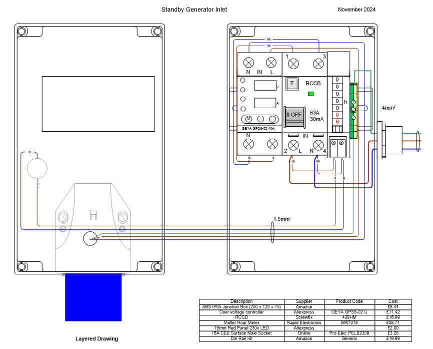
Construction was very straightforward, I start by making a dimensioned drawing using Visio of the enclosure and all parts to be used, this allows me to play about with the layout and finally print the front label which I use as a cutting template for the any holes required.
The parts were relatively inexpensive apart from the hour meter which functionally wasn’t required but is a ‘nice to have’ to monitor the generators onload usage to the house.
House Connection
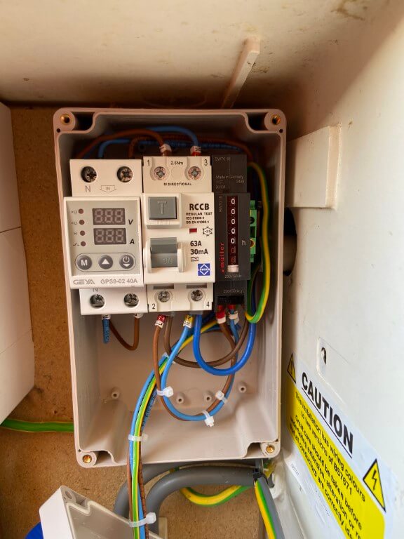
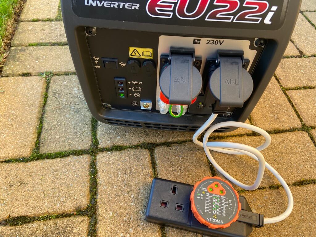
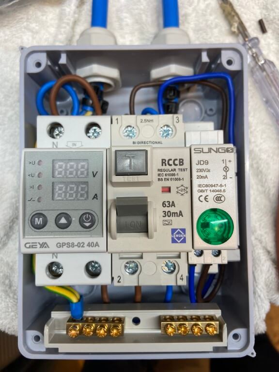
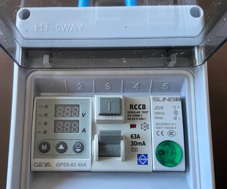
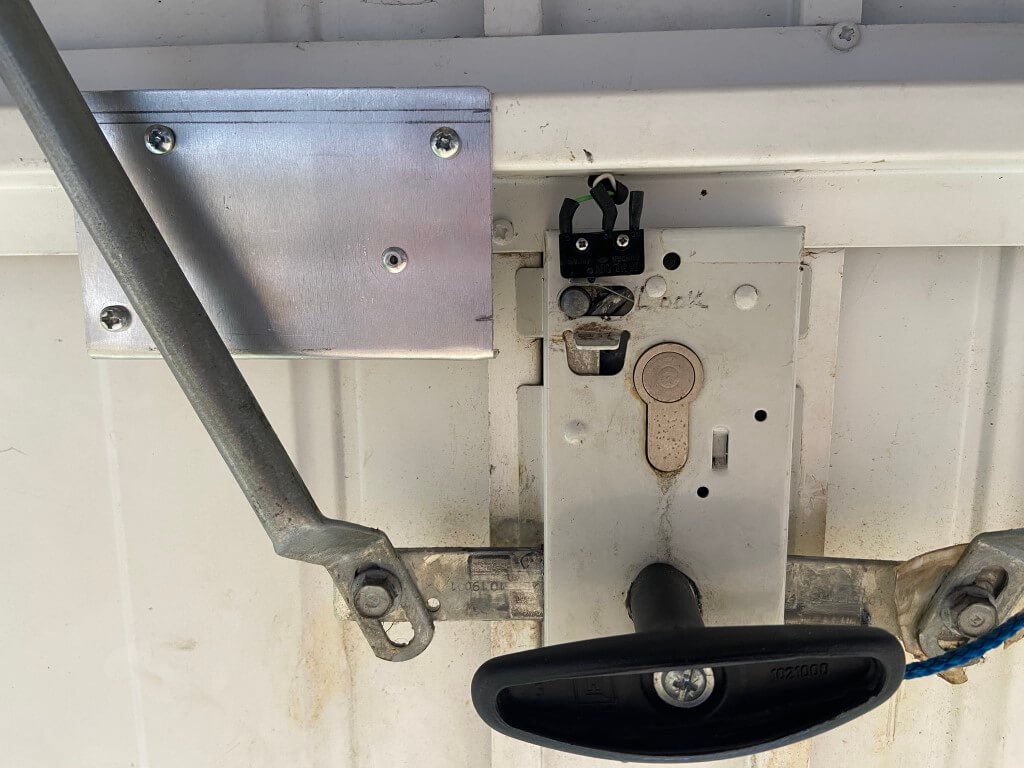
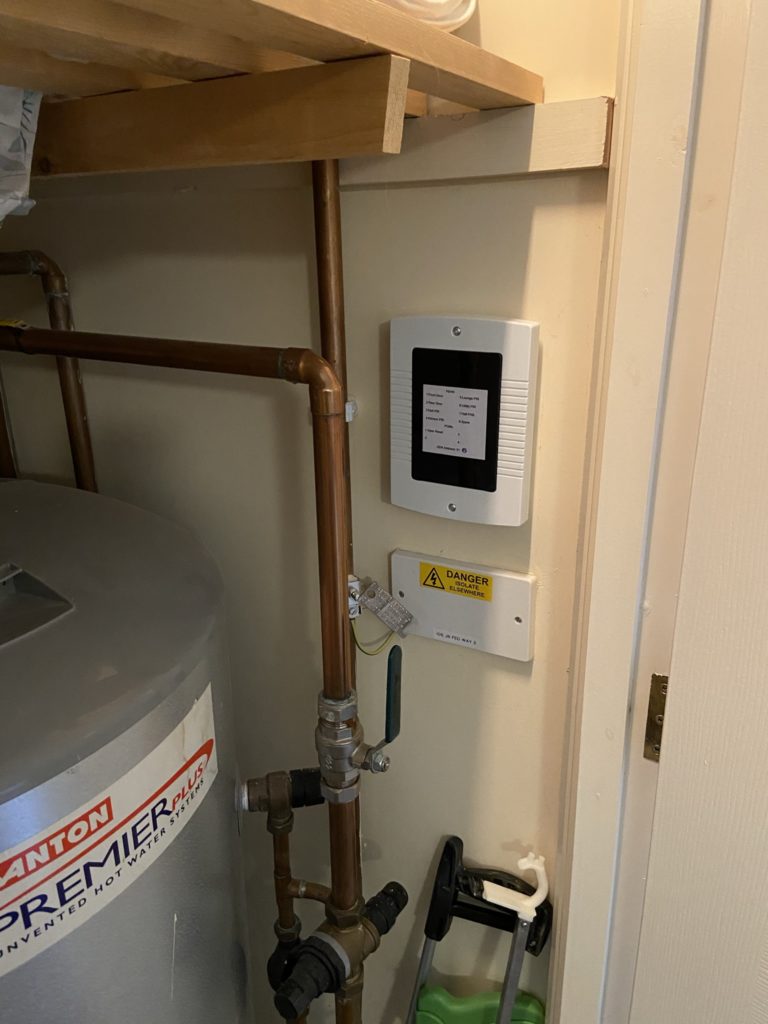
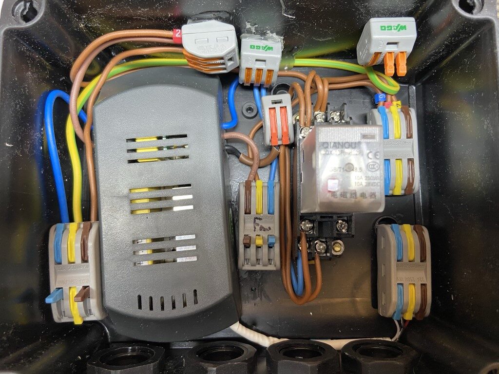
The original connection from the generator to the transfer switch has been removed and replaced with one containing a voltage and current protector, a 30mA RCCD and an hour meter to monitor time off grid.
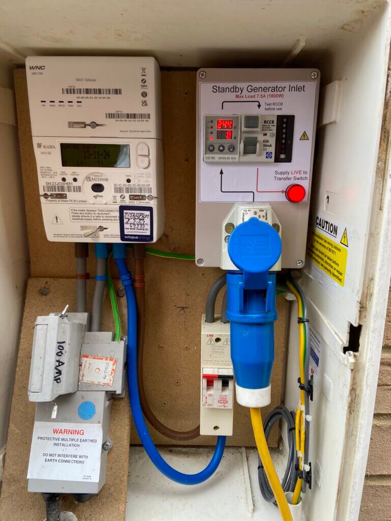
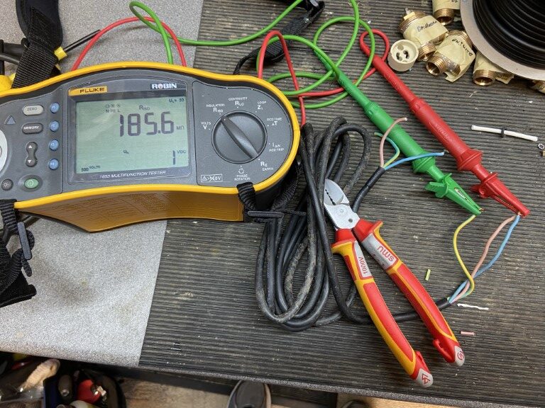
The above image shows the standby generator inlet powered externally from the EU22i without any load, the voltage and current protector GPS8-02), is displaying the actual generator voltage of 244v AC, the voltage and current protectors internal contactor will disconnect if any of the follow occur:
- Voltage out of 210v – 252v range
- Current over 7.5A
The Red LED indicator illuminates when the generator is running with the RCCD ON and controllers output is within the set parameters.
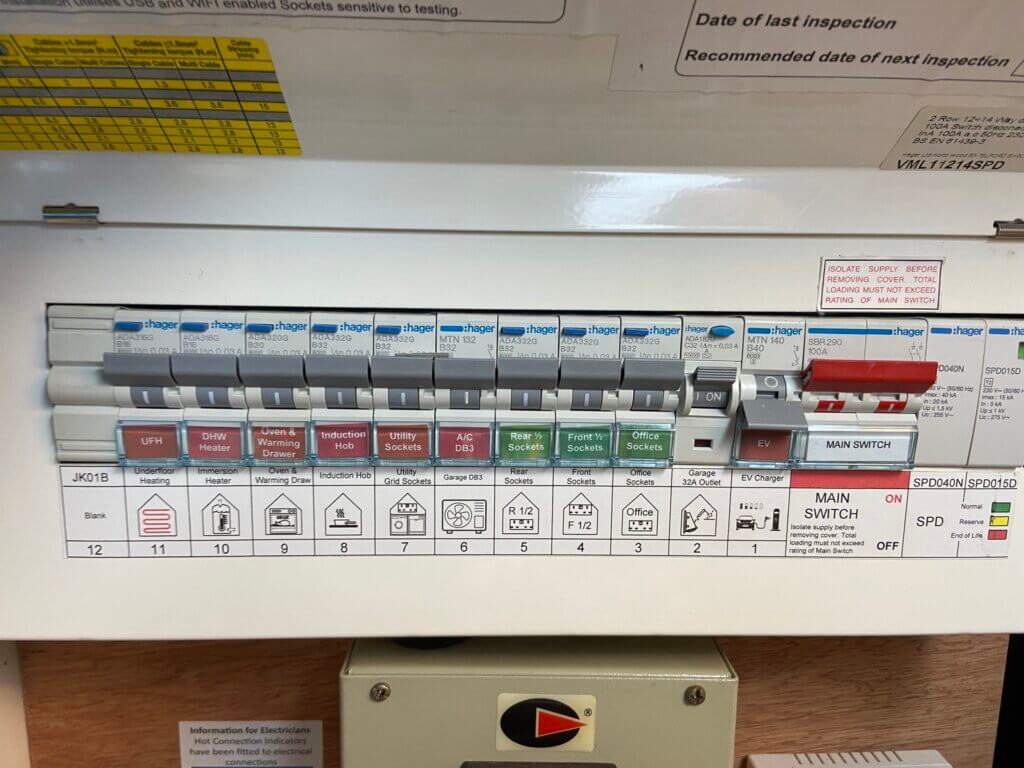
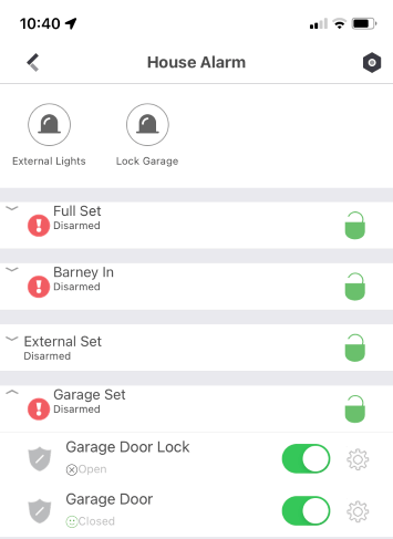
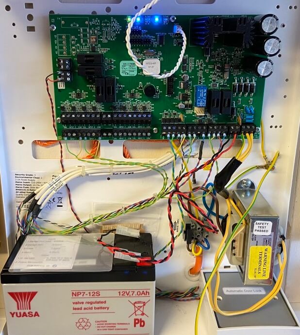
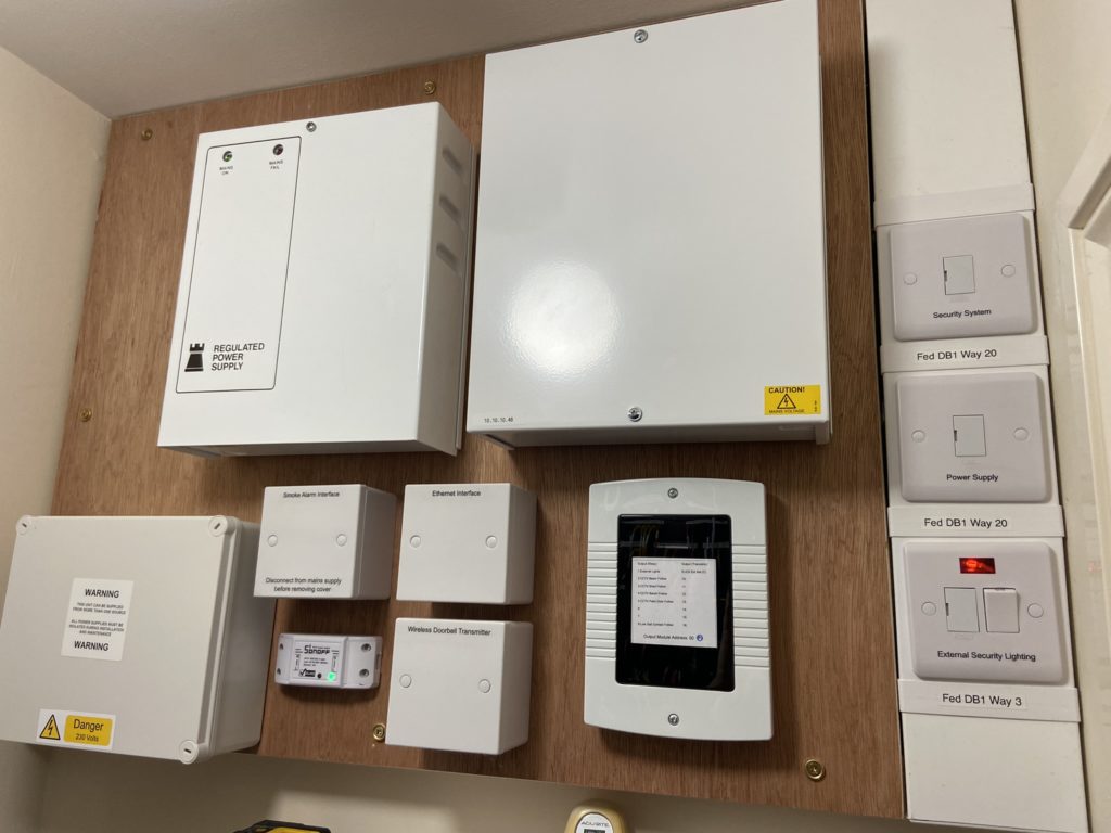
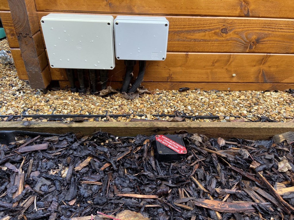
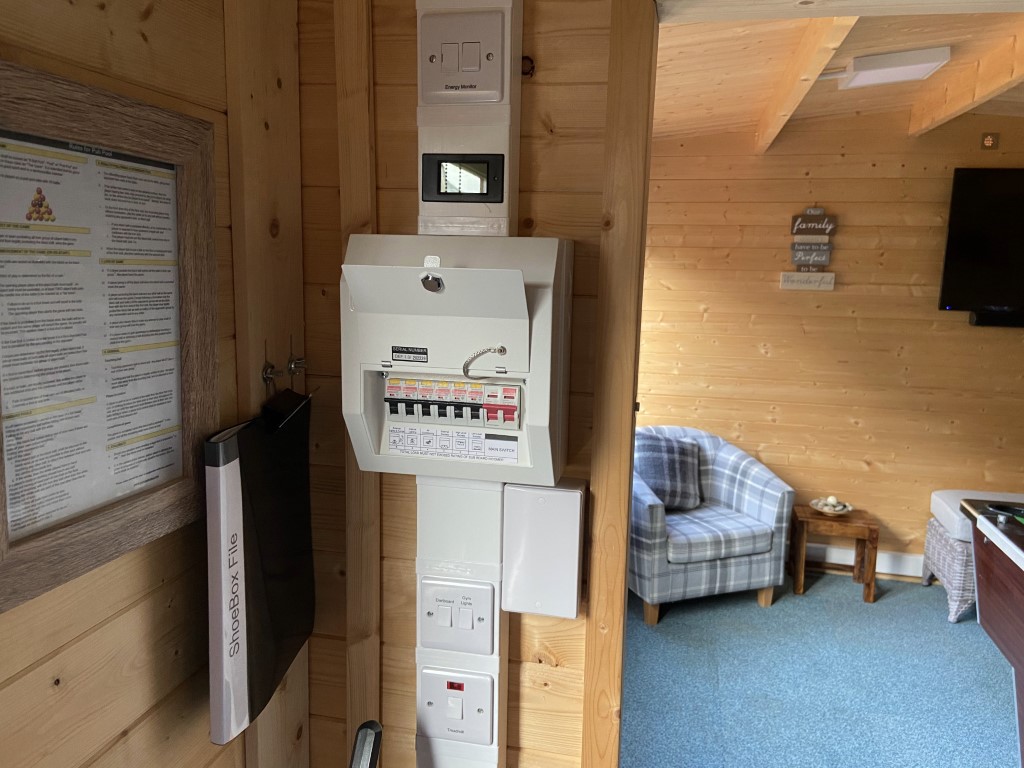
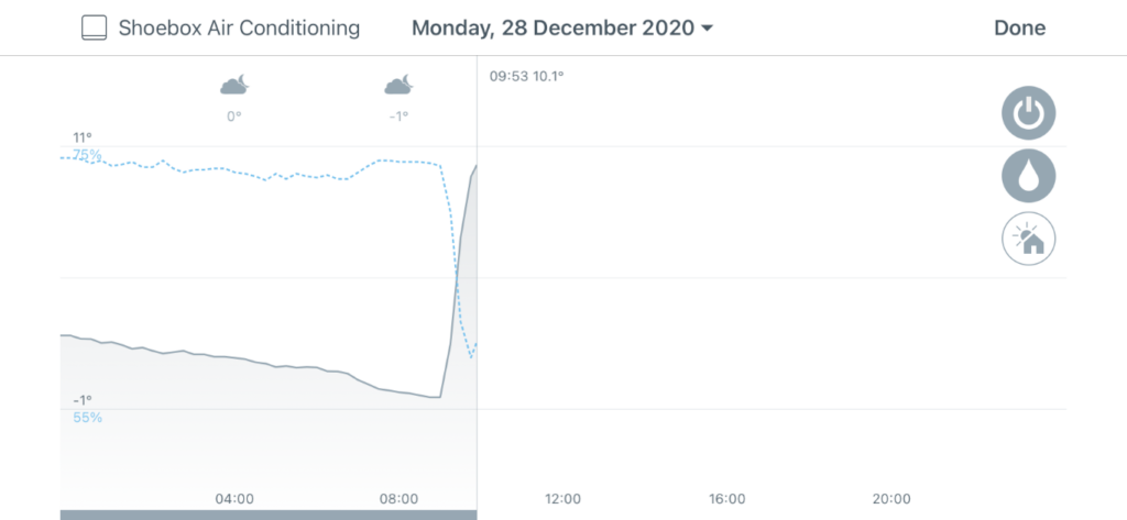
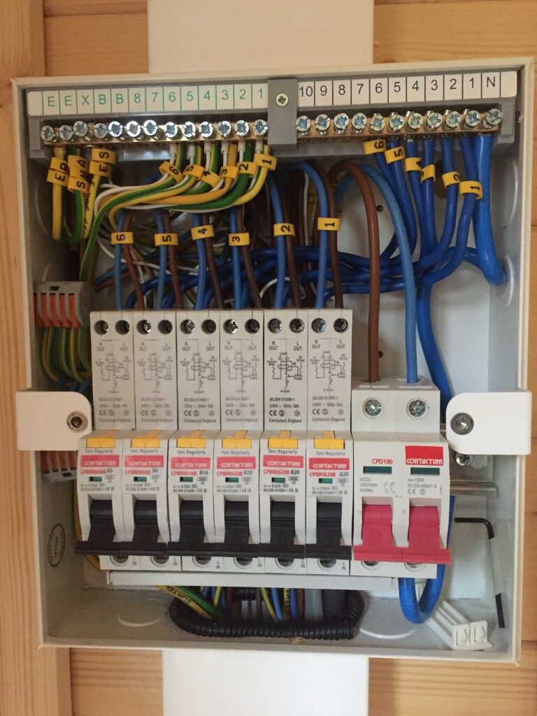
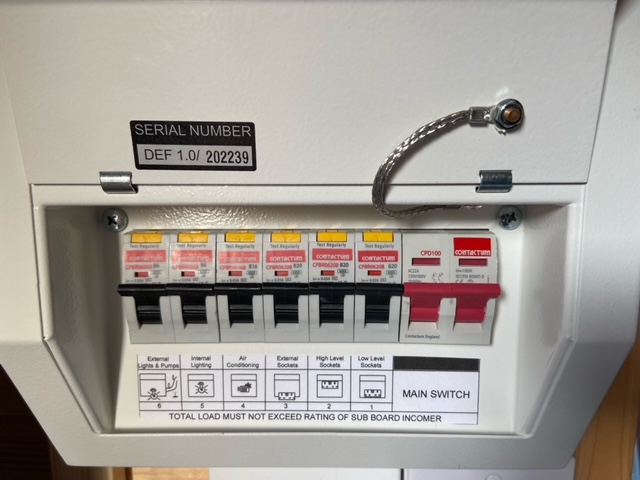
Image of power transfer switch below the consumer unit in the garage, below is an image of the consumer unit RCBO descriptive labels which are either Red or Green, if RED, then they must be turned OFF in advance of the generator power being switched over with only the GREEN left ON.
Electrical Connection Overview
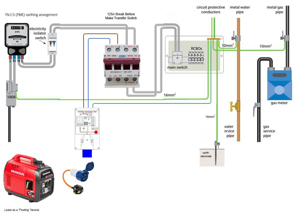
First thing to note is that the generator is separated from the Utility power system by a ‘break before make’ switch, specifically designed for the purpose of external network protection, with this arrangement it is not possible to ‘back feed’ into the network and possibly cause injury to downstream workers.
The house supply is TN-C-S or PME, I had previously installed an Earth Rod for two reasons, the first was to remove reliance on the DNO protective conductor being the single point of failure and the second was to ‘Ground’ the otherwise ‘floating neutral’ of the legacy open frame generator in order for the RCDs to operate.
I wanted to retain the neutral – earth bond on my new Honda generator and so I contacted Honda Directly for the information.
NOTE: Earthing is the biggest area of debate regarding home generators, please do your own research on this complex area.
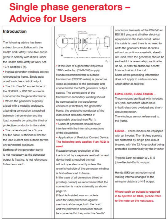
Honda Position on a Bonded Neutral
After many frustrating phone calls and emails both to Honda UK and my Honda dealer regarding conversion from a floating earth to a bonded neutral – earth on my EU22i generator, I was told the information I required was in the Service and Warranty Book which I don’t have, anyway below is the relevant information:
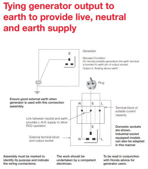
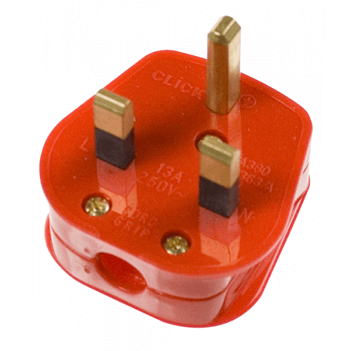
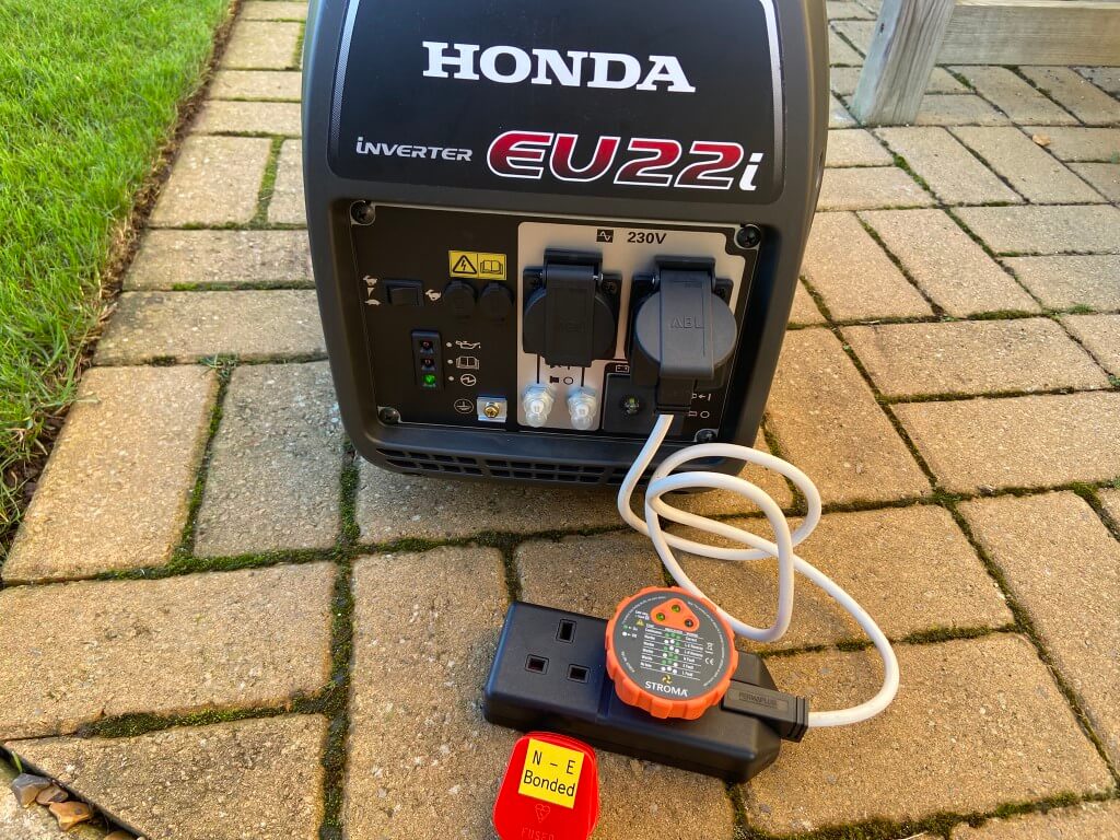
In light of the above information I bought a red plugtop and internally linked the Earth and Neutral together which I will plug in one of the generators outlet sockets whilst using the other socket to feed the transfer switch.
Bonding test in action
With the generator running and a socket tester plugged into the extension lead, the tester showed 2 leds indicating and Earth Fault as expected.
With the Red, Neutral/Earth connected plug inserted into the generators socket, the socket tester lit 3 leds indicating that the socket wiring is correct with no adverse effects observed.
My Initial Concern Over a Bonded Neutral
I have retained this section for information only to show my thought process and rational for not simply jumping in and bonding the Earth to Neutral with the consequential risk of costly damage.
The above is the wiring schematic of the Honda EU22i with the addition of voltage measurements I have taken and a guide image inlay of a split load transformer.
I wanted to establish if the generators chassis ground screw was connected to anything other than the chassis, ideally I was looking to see if the neutral and chassis were directly connected, this would give me a fixed reference voltage and replicate my existing incoming electrical supply configuration.
Results:
- Socket earth pin to chassis ground screw – Continuity and 0v AC
- Socket live pin to chassis ground screw – 120 v AC
- Socket neutral pin to chassis ground screw – 120v AC
- Socket live to neutral – 244v AC
Conclusion before Honda clarification
The generators inverter output is split phase, effectively two live conductors when measured to the chassis, therefore, bonding the neutral to the chassis would cause a direct short circuit of one half of the inverters output and I’m assuming ‘magic smoke’ would soon follow.
In light of this, I have made no modifications to the generators output (no N-E plugs etc) and instead opted to earth the generator to the house earth via the plug and add a global 30mA RCCD on the generators output.
The consumer unit does have RCBO’s, but I’m not bothered by selectivity of device operation in an outage, overcurrent again will be globally managed by the GPS8-02.
12v DC
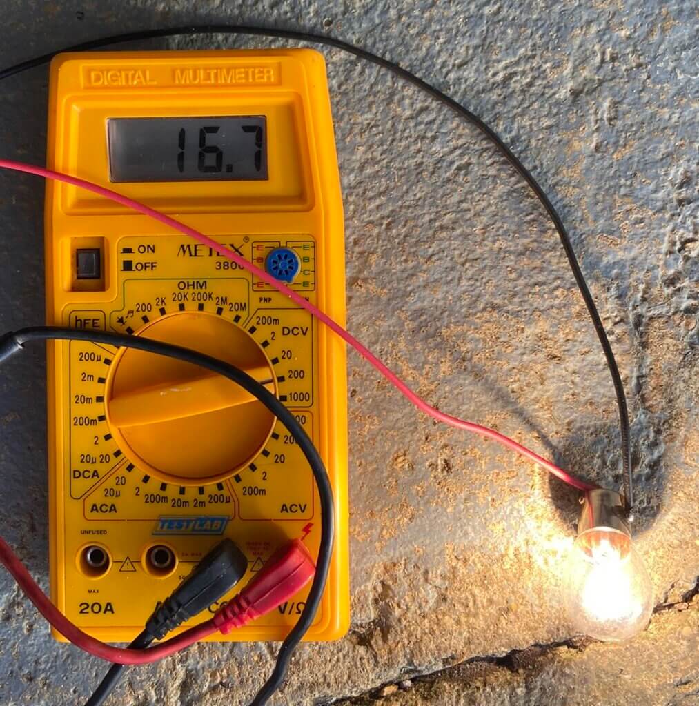
I don’t envisage using the generators 12v DC output, however, I did measure the voltage and though I’d share the results:
- Eco Mode – no load voltage = 16v DC
- Eco Mode – across 21w load = 11.2v DC
- Non Eco Mode – no load voltage = 33v DC
- Non Eco Mode – across 21w load = 16.7v DC
Just one to note!
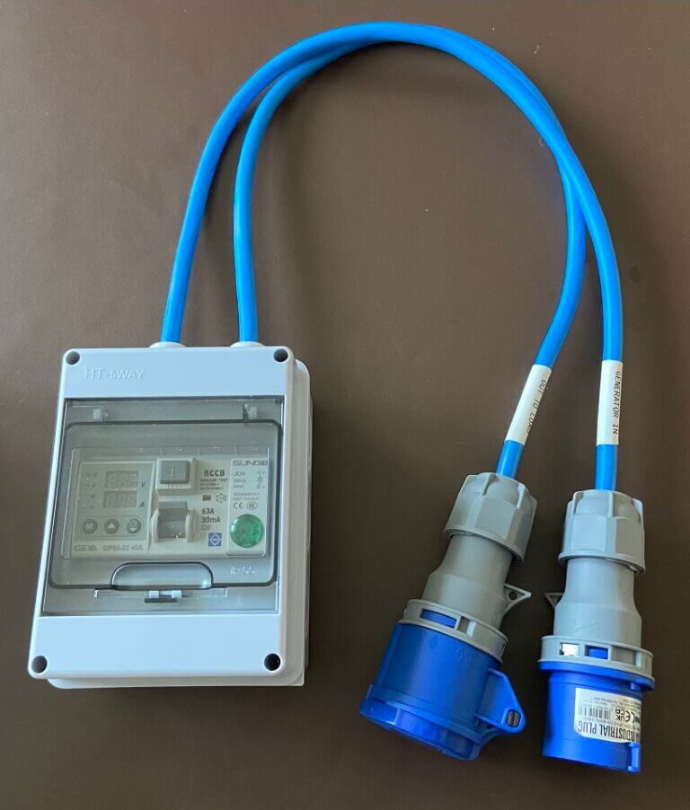
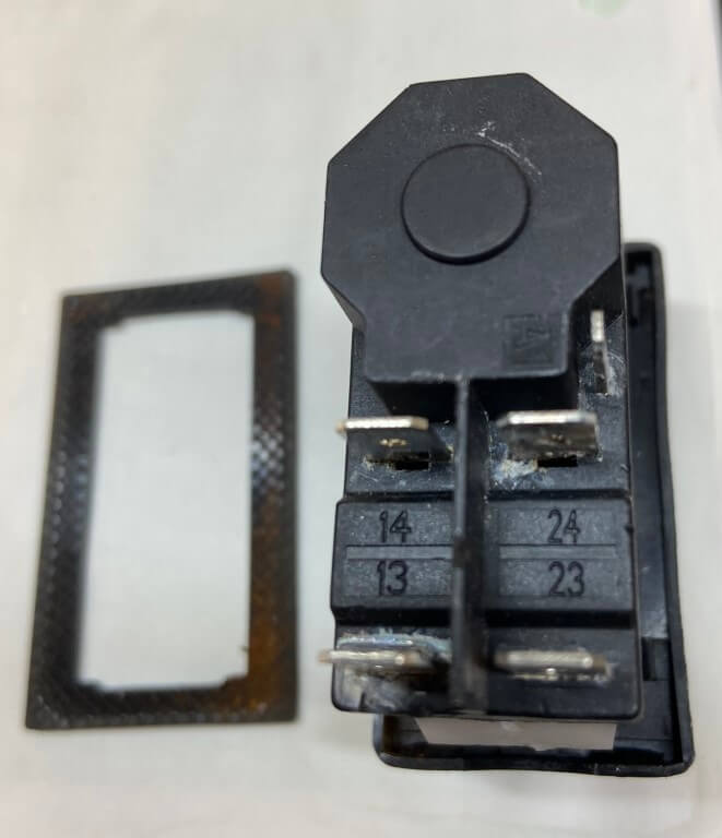
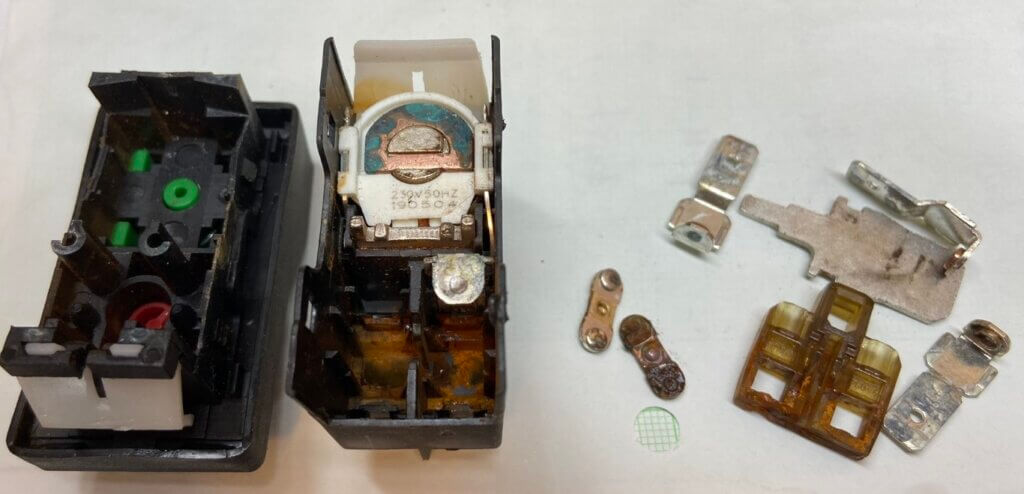
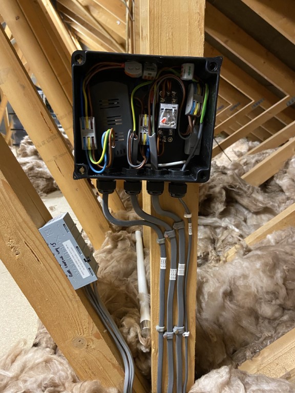
MkII Inlet Version
A family member asked me to build generator and load protection for his home setup, so I tweaked my static version for portable use and have done a write up on it should I need to make more, parts were bought from Ebay, Amazon, Toolstation and Aliexpress.
As you can see, this version is fully portable and can be connected inline either at the generator or the load end, also it has a rating of IP65 offering a level of protection water ingress.
The clear lift up flap allows the status of the device to be observed without exposing the internals to moisture.
Construction was straightforward, the most time on the build was spent waiting for some of the parts to arrive from Aliexpress.
Pleased with the finished unit and wish I’d done something similar for mine 🙂
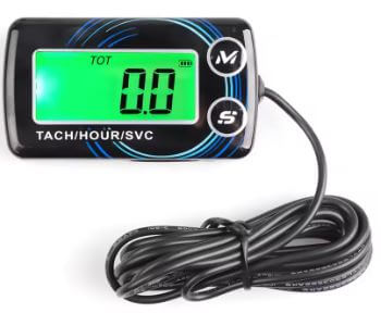
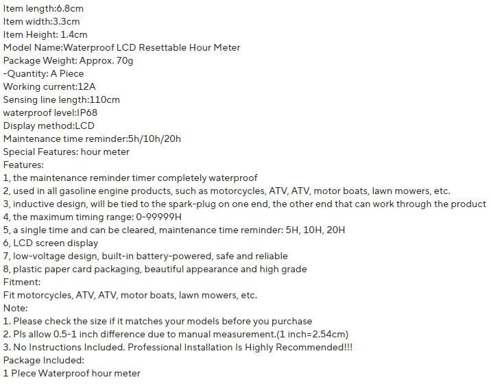
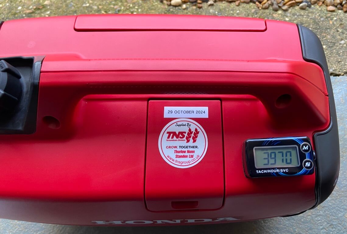
Tacho/Hours Run/Service Reminder Gadget
Bought this from Aliexpress for £9.99, I could have got a cheaper one but this uses a replaceable battery whereas some of the less expensive ones don’t.
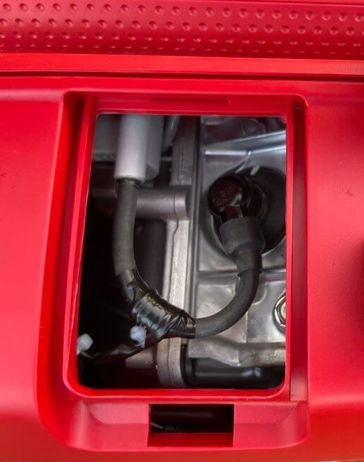
Installation was very easy using a supplied self-adhesive pad to adhere the meter and I routed the sensor wire which wraps around the spark plug lead 5 times through the generators front vent so as not to make any holes in the generators casing which may invalidate the warranty.
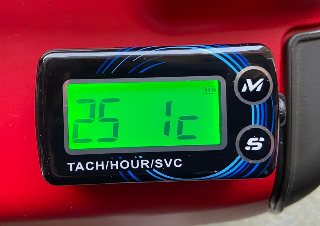
The next part was to check and adjust the settings on the meter, pressing and holding the ‘M’ button enables you to scroll through the menus and make changes.
The main setting was the engine type, I originally had this set as being a 4 Stroke single cylinder (45 1c) engine but the meter displayed over 7000 RPM on engine idling which seemed way out.
Asking on the Facebook ‘Honda Owners Generator’ group about this, they kindly educated me that the Honda generator uses a ‘wasted spark’ system which I had not heard of before, and the answer was to change the meter engine settings to a 2 Stroke single cylinder (25 1c) basically halving the reading due to two sparks being generated on each revolution of the crankshaft.
After doing this, the generator idling, the RPM shows 3970 and in ‘Eco’ mode, the revs drop to 2830.
For me the main purpose of the meter is to monitor hours running and service timer, however, it’s nice to have a RPM indication.
What is a Wasted Spark?
Google was my friend as I’m not a mechanic, I found an excellent article on the GTC web site, so put simply, with a wasted spark system, a spark is generated on every rotation of the crankshaft even though a spark is only required when the fuel/air mix is at the top of the compression cycle in order to combust the mixture with the resultant expansion of hot gasses pushing the piston down.
Any other spark is wasted.
- 1 – Fuel/Air mixture drawn into combustion chamber,
- 2 – Piston compresses fuel/air mix and SPARK,
- 3 – Expanding gasses push the piston down,
- 4 – Piston pushes exhaust out of the cylinder and a wasted spark is sent to the spark plug.


