
This is a follow on from my Dunster House cabin build blog, please note that this work is notifiable under Part P of Building Control Regulations and should only be carried out if competent to do so.
I broke the cabin wiring process into a number of parts, these are:
- Expected use of the cabin
- Cabin power demand
- Submain cable size, type and installation method
- Existing house supply characteristics
- Installation method within the cabin
Expected use of the cabin
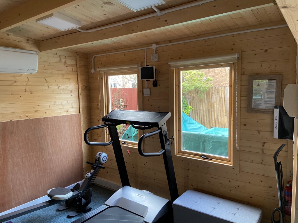
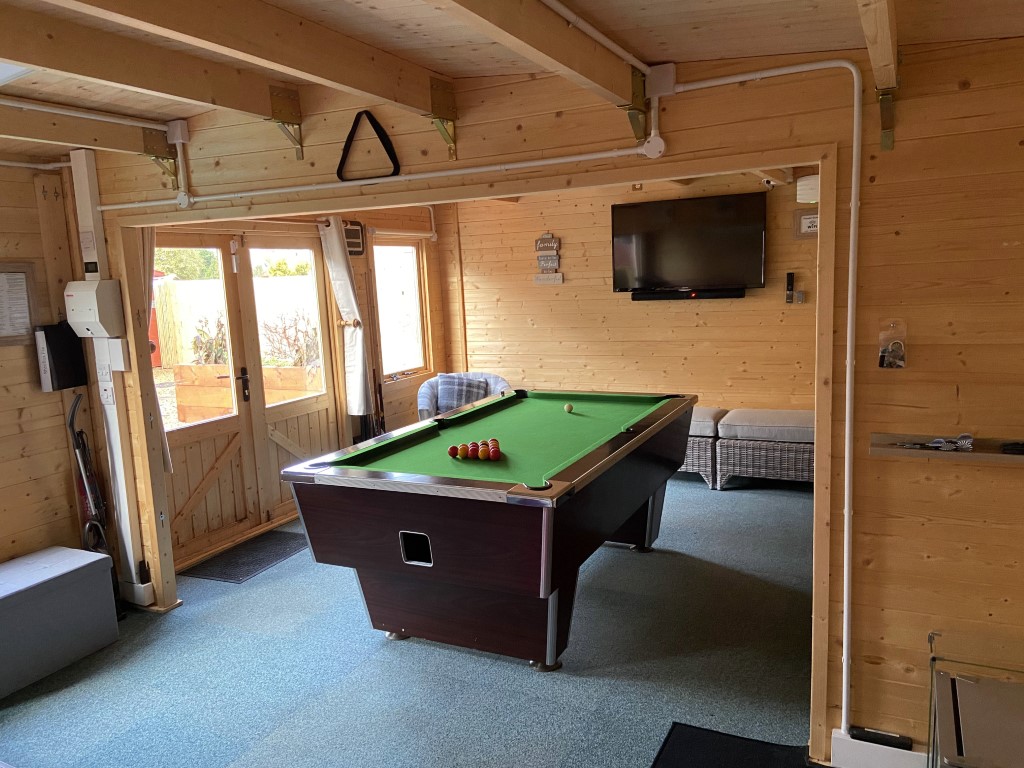
The cabin is for recreational purposes and will be used throughout the year, this means provision will be needed for TV, lighting , gym equipment , general power both inside and outside of the cabin, exterior lighting, internet and a way to not only heat the cabin in the winter, but to cool it in the summer, all this builds a picture of power demand.
Heating the cabin will take the most power, so I used an online calculator work out heat loss and the energy required to raise the cabin temperature to 20 0 when the outside temperature is 00 , this worked out to be just under 4kW, I then allowed a further 2kW for an external plug-in patio heater should we be sat outside.
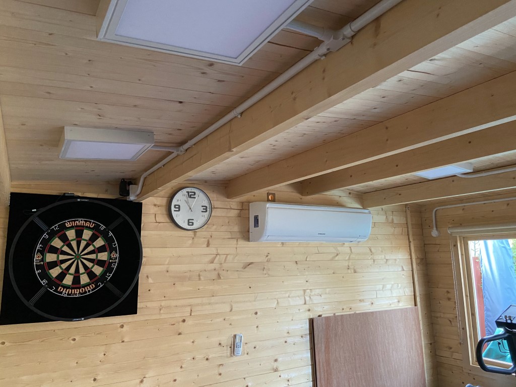
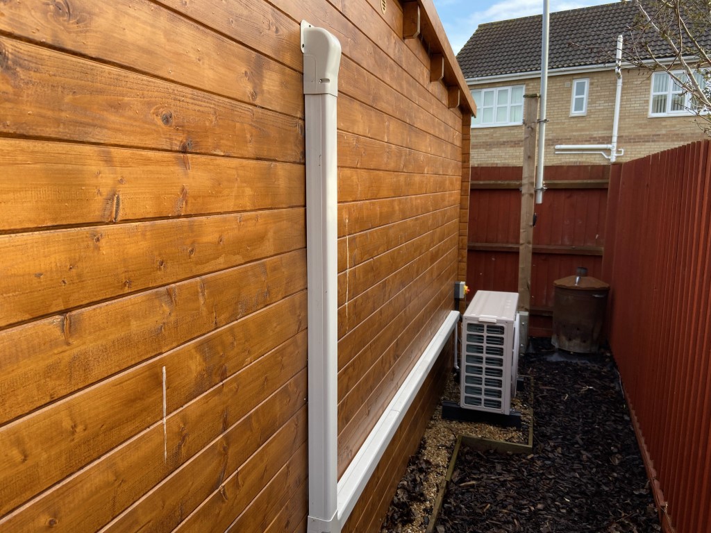
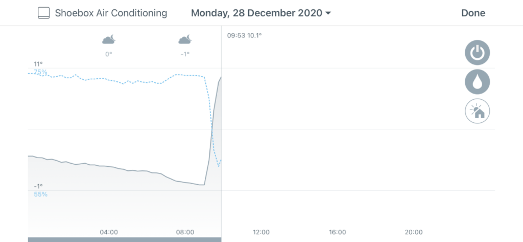
It is equally important that the cabin can be cooled for used in the summer, the highest temperature recorded in the cabin so far was over 42.40 on the 19th July 2022, so the installation of an energy efficient Samsung AR18RXFPEWQX heat pump (5kW Cooling/6kW Heating capacity) was an obvious choice with a rated power consumption 1745W during heating.
Fixed loads such as treadmill, fridge and TV within the cabin are calculated to be 750W.
Inside and outside lighting is low energy LED and comprises of a total of 12 x 20W luminaires.
Maximum Demand
Adding the predicted loads together gives a demand of just under 5kW or 21.7 Amps, however, this is not the correct method, applying BS7671 18th Edition On-Site Guide Appendix A for diversity of circuit loadings, the maximum demand based on known and unknown loads after the application of diversity allowance factors and engineering judgement is 36.65Amps (8.43kVA).
The breakdown of this is:
| Way | Circuit | Load W | Amps | Diversity Factor % | Demand |
| 1 | Low Level Sockets | 20 | 40 | 8 | |
| 2 | High Level Sockets | 1000 | 4.35 | Assesed | 4.35 |
| 3 | External Sockets | 20 | 40 | 8 | |
| 4 | Air Conditioning | 11.5 | 100 | 11.5 | |
| 5 | Internal Lights | 6 | 40 | 2.4 | |
| 6 | External Lights | 6 | 40 | 2.4 | |
| Sum | 36.65 | ||||
| kVA | 8.43 |
Submain cable size, type and installation method
British Standards 7671 18th Edition in conjunction with the IET On Site Guide (OSG) and manufactures data sheets will enable all the cable calculations to be undertaken, however, their are a number of cable calculation tools online, this is an example of my cabin calcs, although I did do them manually before verifying the results with the excellent online toolkit from jarsoftelectrical (Cable-Mate) :
Project Name : Cabin Submain with Diversity Allowance
Cable ID / REF number : DB1/Way 1 to DB2
Supply Voltage = 230 Volts
Power factor = 1
Ib – Design current = 36.65 Amps
Protective Device Type = MCB type B (BS EN 60898)
In – Protective Device Rating = 40 Amps
Cable Type : Thermosetting ARMOURED 90°C – Multicore
Length of run of cable = 21 metres
Maximum permissible Voltdrop: 3% (Lighting) = 6.9 volts : Appendix 4
Maximum selected Voltdrop for this calculation = 6.9 volts
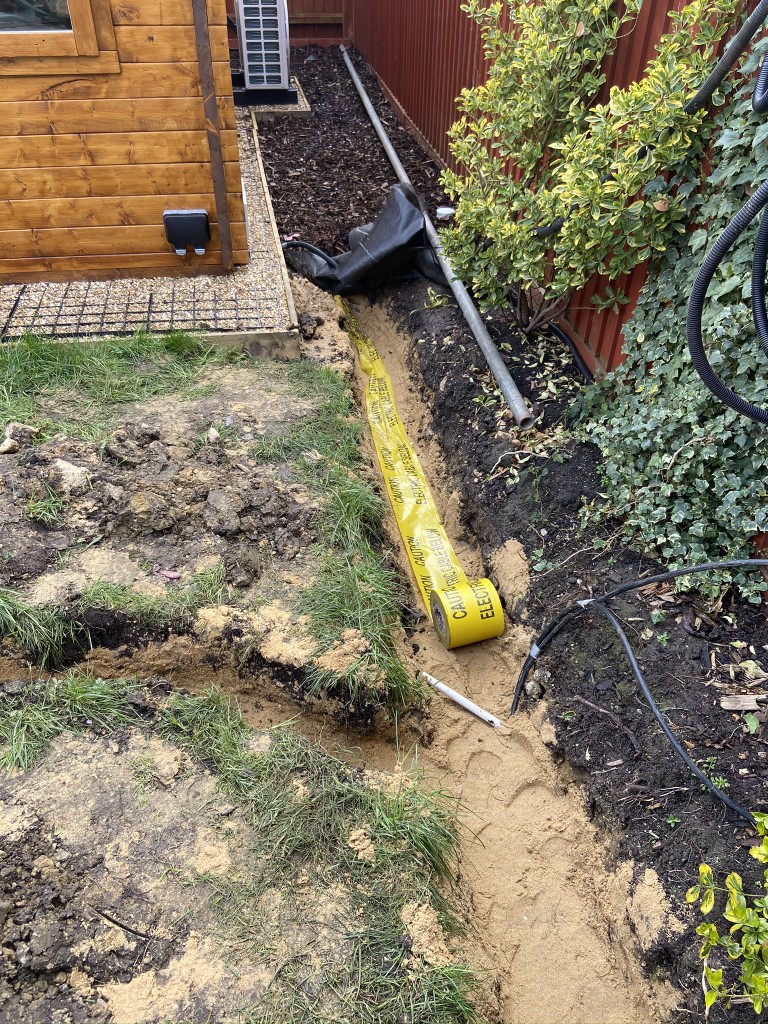
Installation Method : Sheathed, armoured or multicore cables direct in the ground:
with added mechanical protection (e.g cable covers).
An installation depth of 0.5 Mtr, A soil thermal resistivity of 2.5 K.m/W
(method D)
Ambient temp = 20 °C
Number of circuits including this one = 1
Length of cable in thermal insulation = none
Apply Correction factors:
From TABLE 4C2 : Cg = 1 (Grouping)
From TABLE 4B2 : Ca = 1 (Ambient temp) – Ground Temperature : 20 °C
From TABLE 52.2 : Ci = 1 (Insulation)
Protective device factor for Buried cables : Cc = 0.9 (Burried direct)
For an installation depth of 0.5 Mtr : TABLE 4B4: Cd = 1.03
For soil thermal resistivity of 2.5 K.m/W : TABLE 4B3: Cs = 1
Protective device factor : Cf = 1
It = tabulated current carrying capacity
It = In / (Cg x Ci x Ca x Cf x Cc x Cs x Cd)
It = 40 / (1 x 1 x 1 x 1 x 0.9 x 1 x 1.03 )
It = 43.15 Amps
From TABLE 4E4A Cable selected = 6 mm²
Current capacity of cable selected = 53 Amps
TABLE 4E4B For 6 mm²: mV/A/m = 7.9
mV/A/m corrected for power factor = mV/A/m x Power Factor = 7.9 x 1 = 7.9
Voltdrop = (mV/A/m x Length x Design current) / 1000
Voltdrop = ( 7.9 x 21 x 36.65 ) / 1000
Voltdrop = 6.08 Volts
(Maximum permissible voltdrop (regulation – 525) = 6.9 Volts)
Calculated Cable size = 6 mm², Minimum Earth conductor size = 6 mm² (Table 54.7)
Maximum Cable Length = 23.8 Metres
My calculated maximum demand is the worst case, it is highly unlikely that the sustained loading on the cabin will exceed my original value of 21.7Amps based on predicted usage, however, I have designed the installation to meet the current regulations and that includes cable sizing, I could have gone for a 10mm2 SWA cable but that would have been over-engineering in my view as all regulatory requirements are within parameters.
Existing house supply characteristics
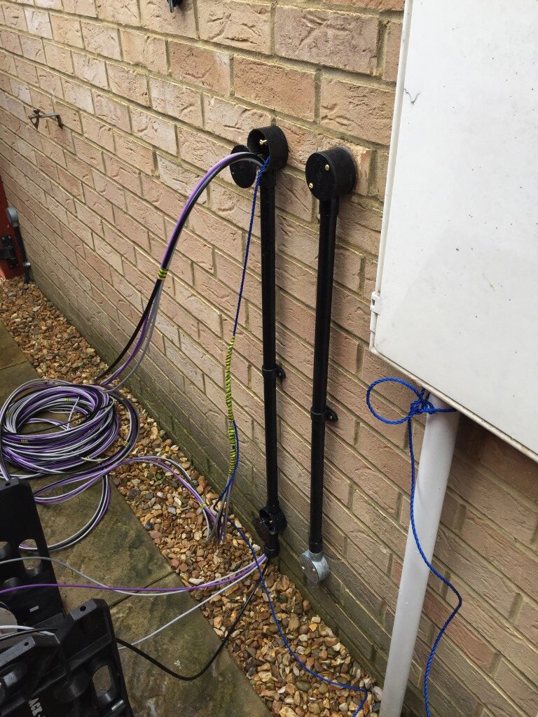
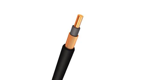
The supply origin is TN-C-S referred to as PME (Protective Multiple Earthing), in this arrangement the incoming cable is of concentric construction:
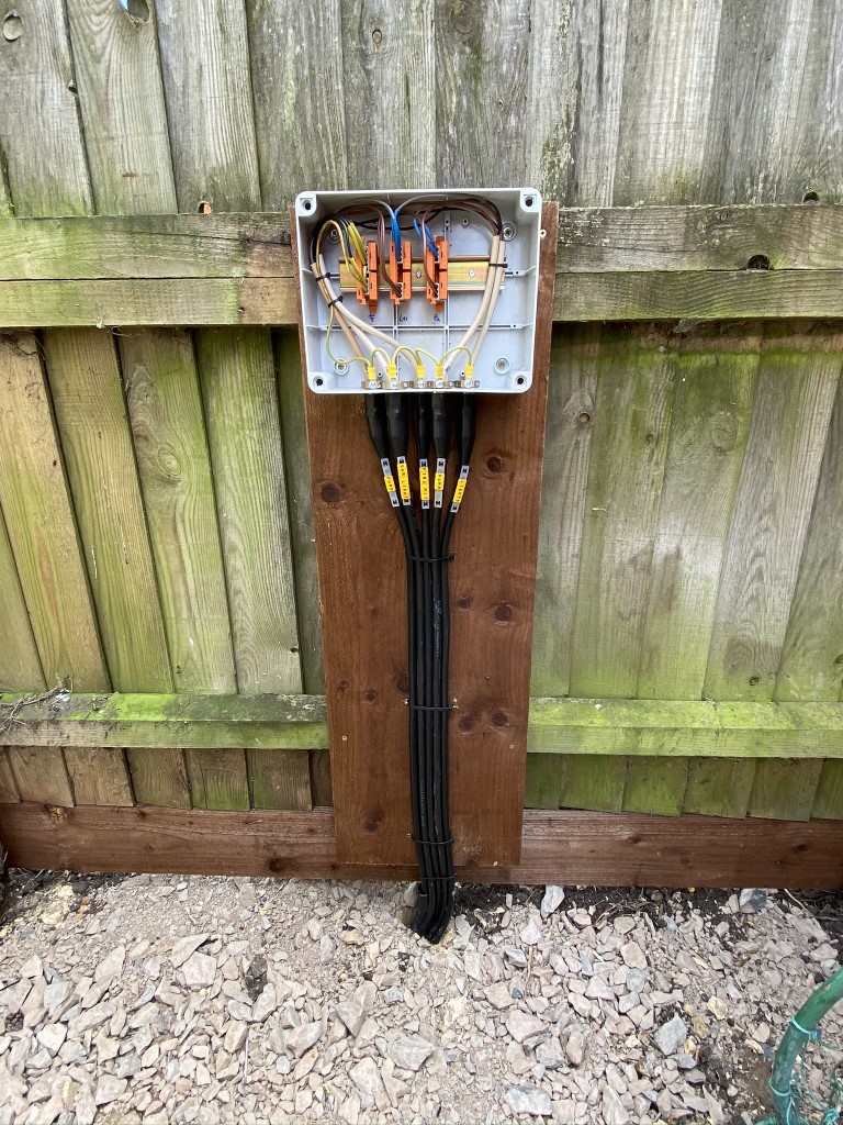
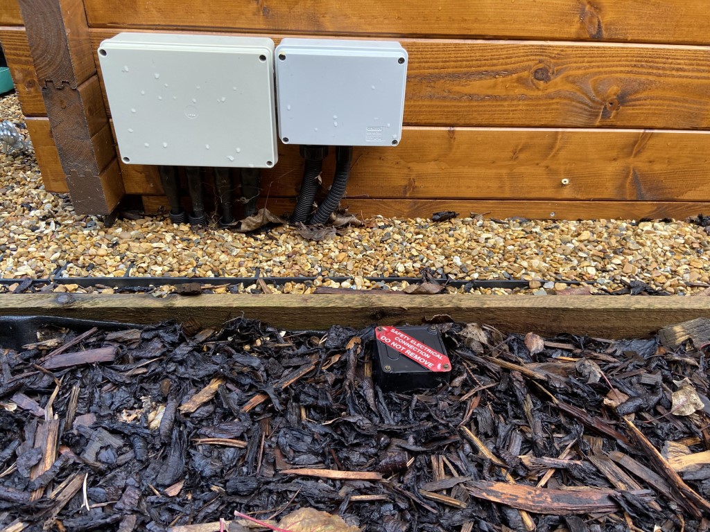
Only if certain conditions are met can this type of supply, including earthing, be extended to outbuildings, I therefore opted for a TT supply to the cabin which will have its own independent earth electrode with all cabin circuits protected by RCBOs (Residual Current Circuit Breakers with Overcurrent protection).
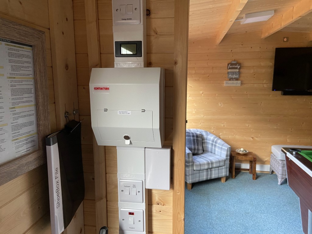
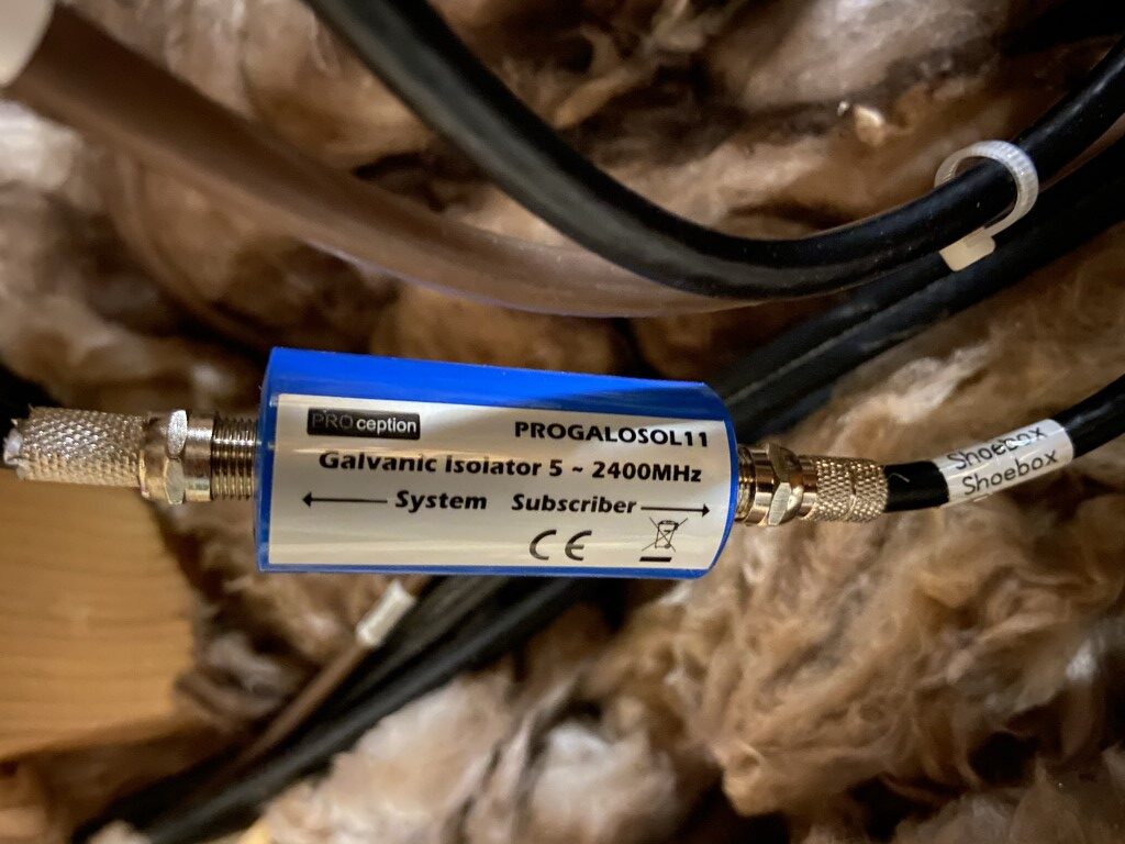
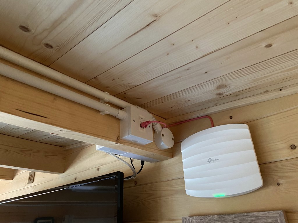
With a TT arrangement it is important not to ‘import’ an earth path from the house, therefore the submain SWA terminates into a plastic external enclosure, the TV aerial cable has a galvanic isolator installed to break the shield at the house and the Cat5 internet cables have no connection to earth.
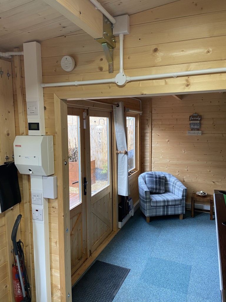
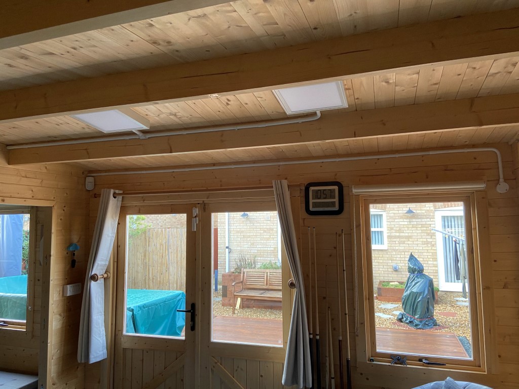
Installation method within the cabin
Wood expands and contracts with humidity by up to 12mm in my case, therefore the wiring method must be able to accommodate this movement, I chose to use Univolt 100mm x 50mm dado trunking installed all around the base of the cabin and to the consumer unit, from this trunking 20mm heavy duty PVC conduit is taken to lighting and high level sockets, this gives me total flexibility to add to the wiring system if needed.
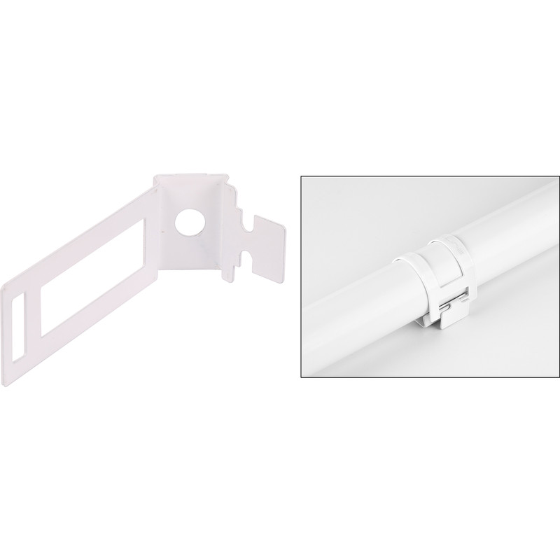
To allow for expansion, I have used a combination of lubricated slip couplings for 20mm conduit joints and flexible conduit for movement transitions where appropriate.
The trunking is capable of having a partition piece inserted to make a segregated trunking compartment, this I have used for data and TV cables.
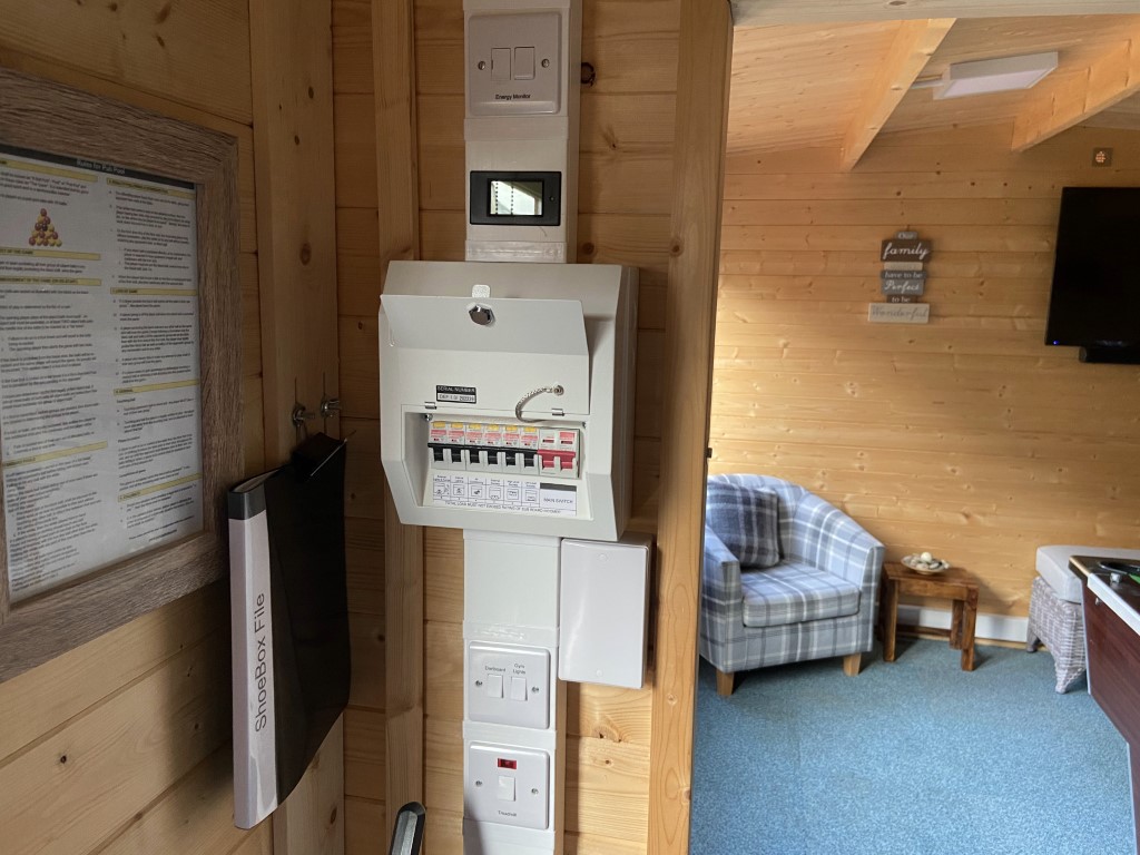

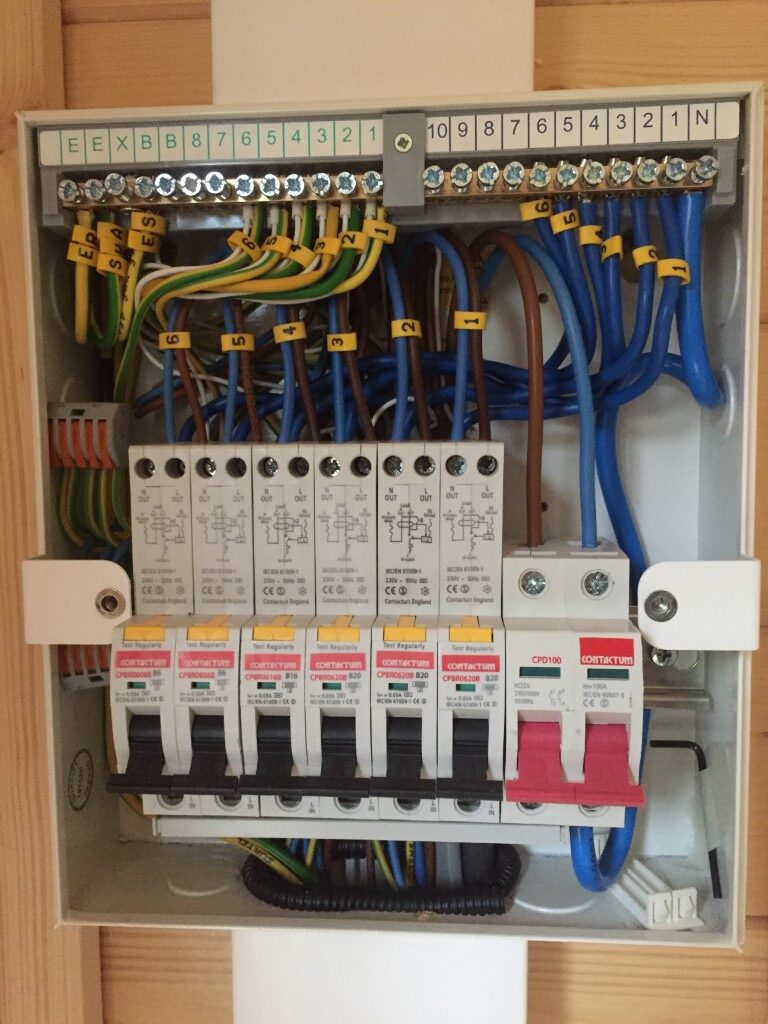
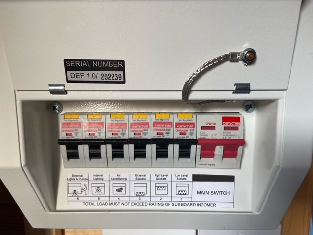
The cabin consumer unit has 6 RCBO protected ways these are for:
- Way 1. Low level dado trunking socket outlets (B20)
- Way 2. High level sockets via conduit (B20)
- Way 3. External IP rated double sockets (B20)
- Way 4. Air Conditioning unit (B16)
- Way 5. Internal lighting including emergency light (B6)
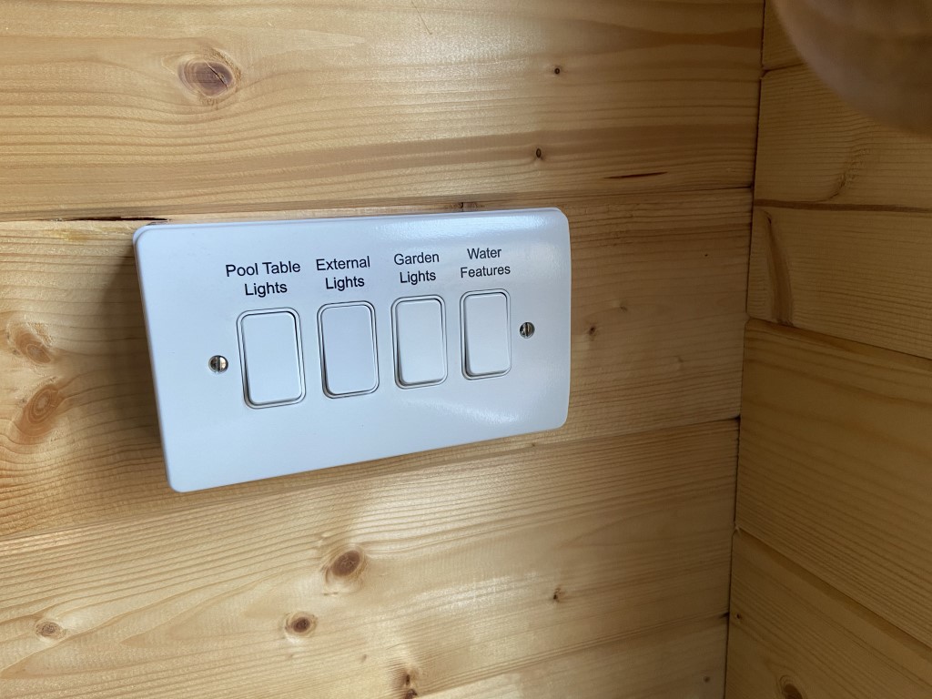
- Way 6. External lighting and water features (B6)
The cabin area is 29.25m2 and the OSG Table H2.1 final circuits to sockets outlets are Type A3, Radial using 2.5mm2 singles.
Low level dado trunking has 13 double sockets, the vast majority are not used but as the cost per socket is less than £5 it was worth doing, the high level socket circuit only has 1 double socket and one single socket so I’ve assed the maximum load to be 1000w as these sockets are dedicated to low wattage chargers and a TV it is highly unlikely this will be exceeded, especially considering the number for dado sockets 🙂
I have installed 3 double IP rated external sockets as a separate Type 3 Radial circuit.
Internal lighting cables are all 1.5mm2 singles, external lighting and water feature cables are 1.5mm2 SWA.
Update
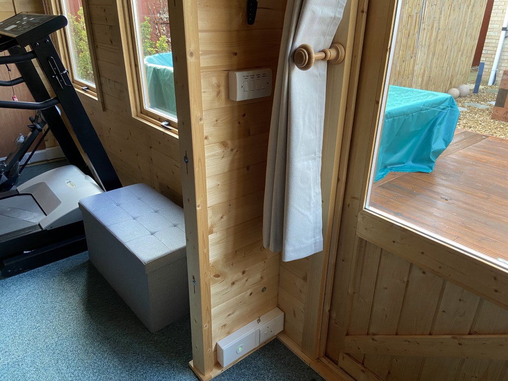
Having used the cabin for a year, one of the things I didn’t install at the time was a means of two way switching the cabins outside lights on or off, I thought the external security light sensors on the house would bring the house mounted lights on if someone left the cabin at night, unfortunately this wasn’t the case, so the first few steps out of the cabin were in pitch darkness, which is less than ideal.
The solution came with Quinetic switches from TLC, these are quite amazing as the switches need NO POWER, they internally generate enough energy to transmit to a receiver which could be up to 30m away.
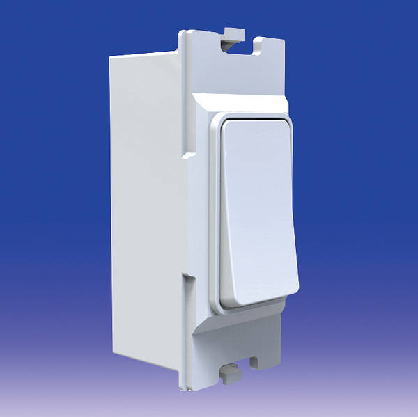
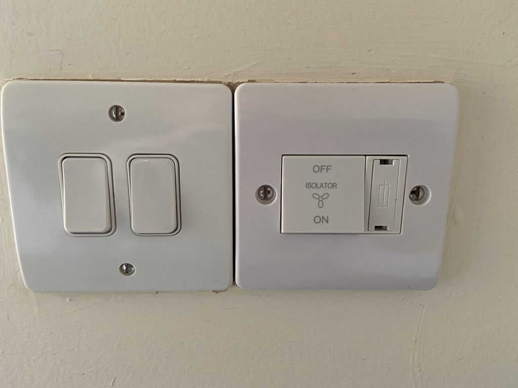
The above picture shows a two gang switch plate, originally this was only a single gang switch for the utility light by the back door, changing this to a grid switch allowed me to have the first switch as the utility light and the second switch as a Quinetic module remotely and wirelessly turning on and off the external cabin lights.
In a previous picture of the cabins four gang switch, the external lighting switch is also a Quinetic module, both paired to a single receiver operating the lights, I also have a keyfob paired to the receiver giving me maximum flexibility in operating the lights.
This modification was very easy to do with no mess, unlike the traditional method of hardwiring and cable chases.