This is part one of a project to install a secondary water meter and automatic shutoff valve to my homes incoming water feed.
The first task was to locate the route my buried plastic (MDPE) water pipe takes to the boundary meter from the house, hopefully I can expose the pipe near to the garage.
The main reason for getting the meter near the garage was to enable easy connection to the Home Assistant interface and to ensure Wi-Fi connectivity to this.
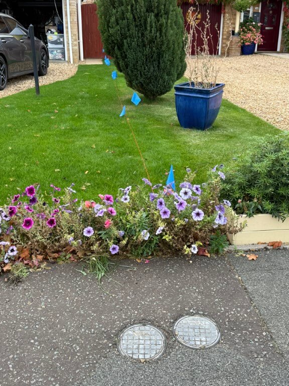
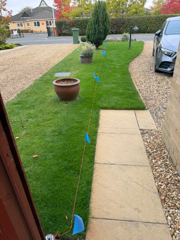
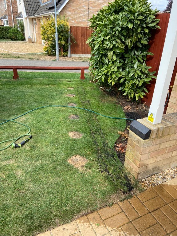
The images show from the boundary meter, (mine on the right!), looking towards the house, whilst the other picture is looking from the house with the assumption that the pipe is buried in a straight line.
The water pipe is 25mm and does not have any buried tracer wires or tracing features, therefore, I cannot use any radio detection avoidance/detection tools to impose a signal.
Excluding Ground Penetrating Radar, I could isolate the water and disconnect the pipe at the stopcock, and from there insert a metal ‘fish’ into the pipes length, giving me the ability to impose a radio signal on this and track it with a Cable Avoidance Tool (CAT), as this was ‘invasive’ and practically, very difficult I opted for the second method.
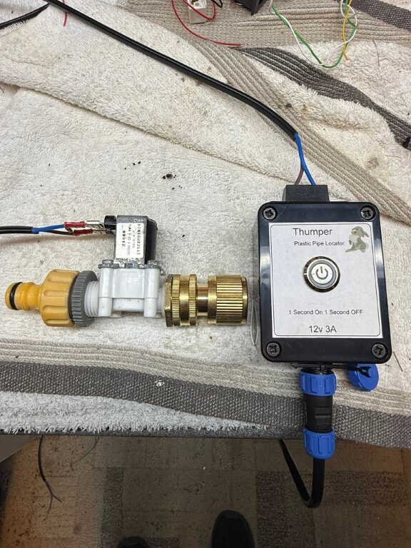
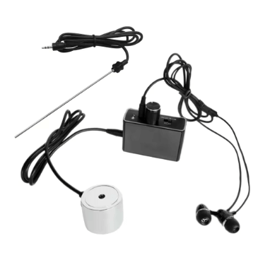
This method involves connecting a pulsing solenoid valve to an outside tap which causes an audible ‘water hammer’ which can be detected with a sensitive microphone, this is called the ‘Thumper’ method.
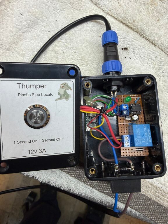
Complete ‘Thumper’ setup, the 12v solenoid valve is from Aliexpress and is pulsed by the circuit contained within the enclosure.
With the water being ‘pulsed’, the next part was to detect to sound and trace the pipes path based on how strong the pulse sounds, bearing in mind that the pipe is buried at least 500mm (should be 750mm, but 500mm was to the base of the existing boundary meter chamber).
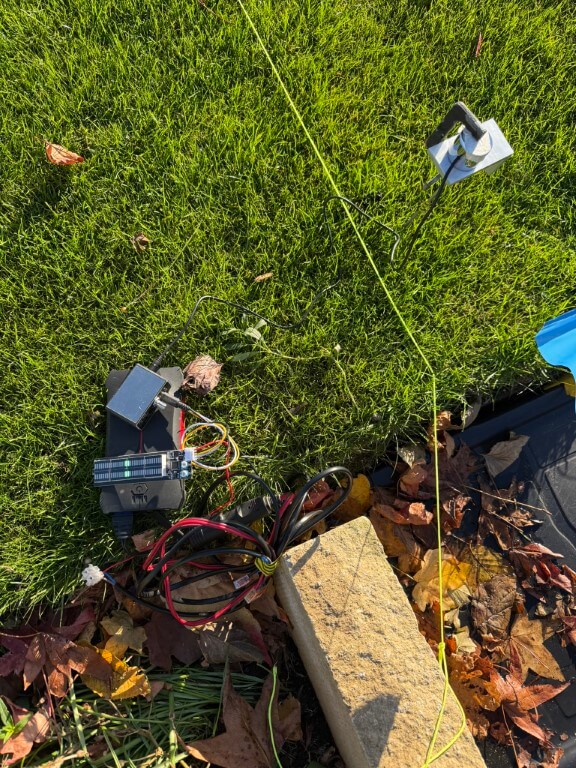
I bought a high sensitivity microphone and amplifier from Aliexpress for £23.99 which is incredibly good, I did clamp the circular microphone onto a piece of aluminum which had a length of stainless steel thin bar tapped into it, this allowed me to push deeper into the lawn in the hope of hearing the ‘Thumper’ noise.
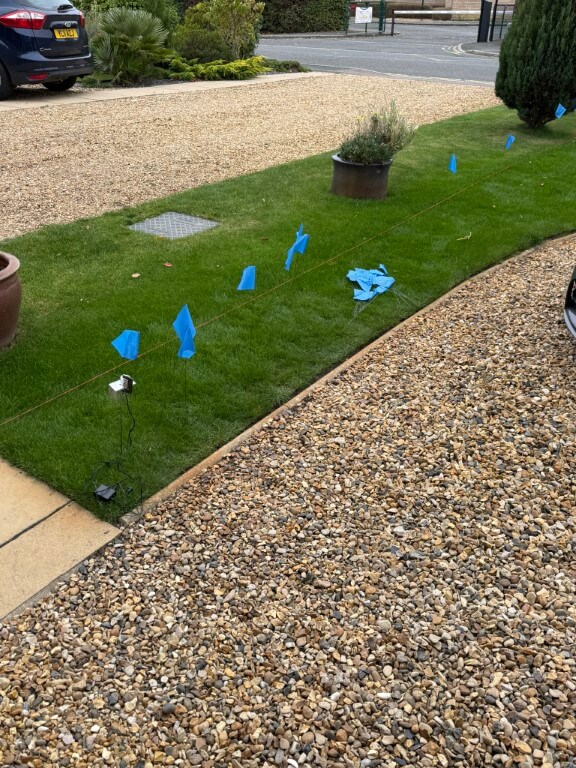
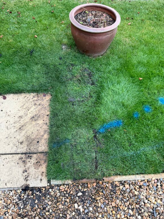
Each time I heard an audio signal, I moved the probe back and forth to find the strongest signal and marked this with a flag, as you can see, the pipe veered off the straight predicted line.
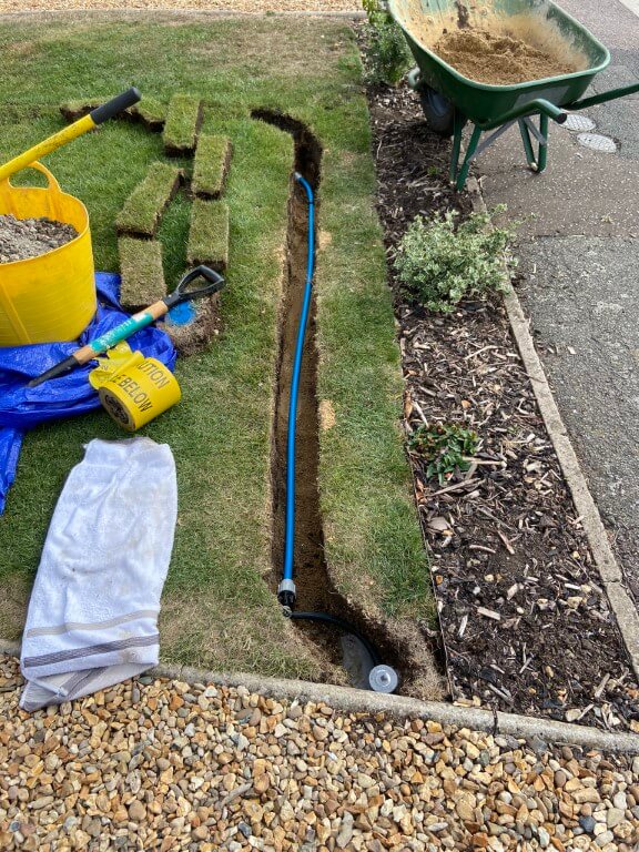
Day 1 – Dig (13 Oct 25)
As it was raining slightly and I don’t want my back to go, I decided to take it easy with the digging.
I started with a spades width rectangle hole and went carefully as I didn’t want to damage any services, I did know that the edging stones were cemented in, but was unsure how far this went under the lawn.
I didn’t have to dig too far down (300mm) to expose the incoming mains electricity and gas on top of the surface water drain pipework.
I checked the black duct using the ‘Thumper’, but its the electrical supply cable to the house, I did dig another hole to the side of this one, but it just confirmed that the surface water drain carried on to next doors property.
Filled everything back in ready for round two!
Day 2 – Dig (17-19 Oct 25)
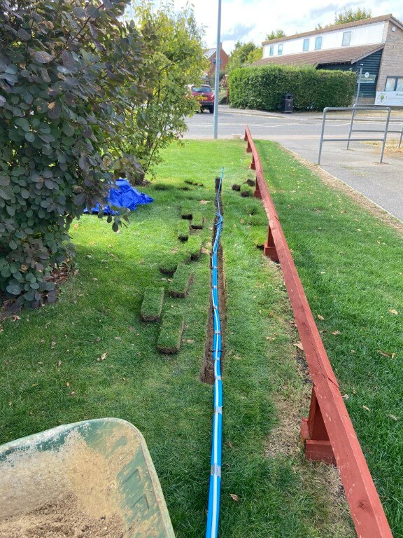
I moved 700m nearer to the meter from the first dig and decided to basically trench across the lawn to give me a good chance of locating the pipe.
After digging 800mm deep and 1000m across, there was still no sign of the water pipe and using the ‘Thumper’, I could hear the rhythmic beat using the high gain microphone, but was unable to ‘hone’ in to a strong signal.
I could only conclude that the vibrations caused by the ‘Thumper’ was being transposed onto the neighbours water pipe and it was this I was detecting, rather than mine!
Day 3- Dig (20 Oct 25)
I wasn’t sure what to do at this point, I did ask for advice on my towns local Facebook page and had a really helpful reply, following this up, I was given a contact number of an ex-Anglian water guy, but the problem was unless the pipe was leaking detection was not possible with the tools and methods he had.
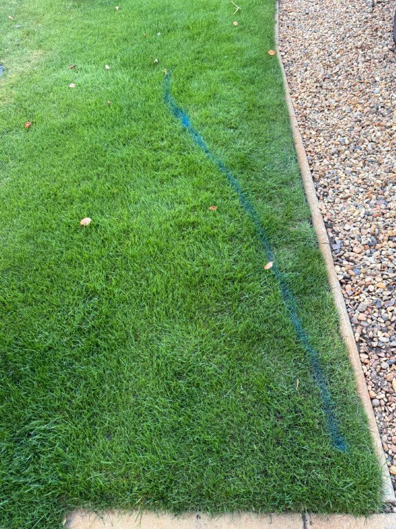
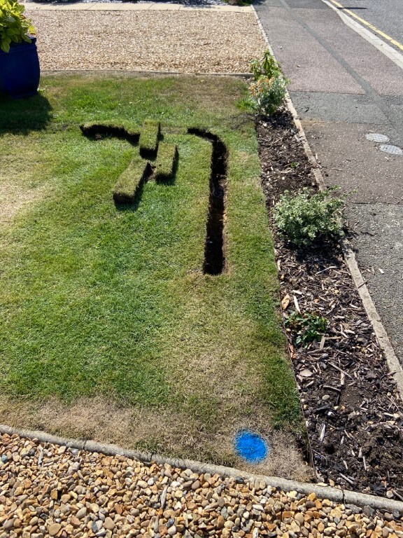
Prior to posting on Facebook a chap at ‘Man Shed’ suggested using water dowsing to find the pipe, when I got home, I was skeptical, but gave it a go with two bits of brazing rod, and blow me it gave an indication.
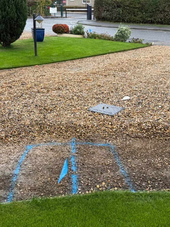
The far blue flag shows the location of the water meter, so I walked at 900 to this across the grass and drive and plotted when the rods crossed, repeating this I finally ended up with the second blue flag and a box location to dig in the hope I find the pipe.
I did also appear to pick up a sewage pipe which traverses across the front of my house.
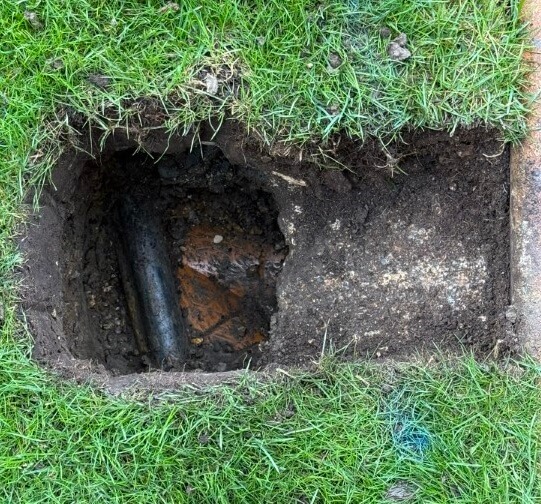
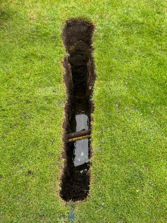
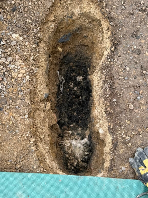
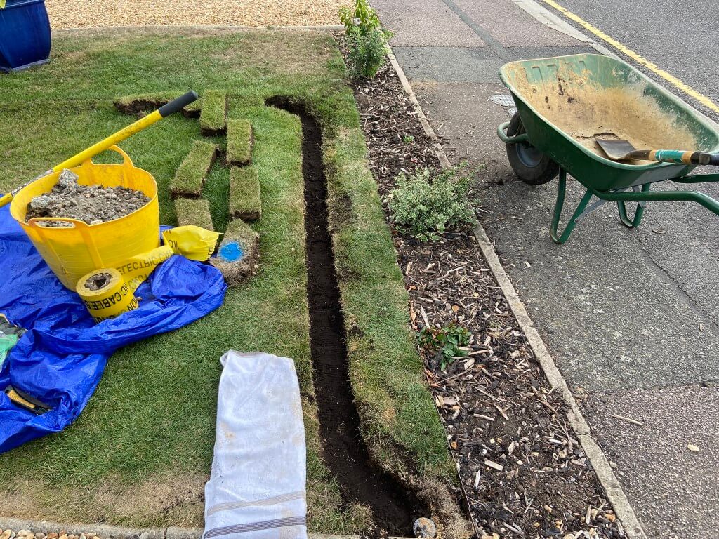
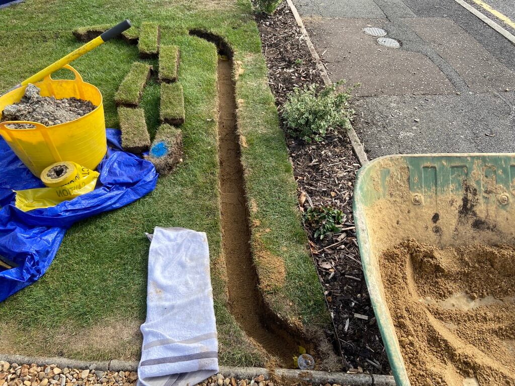
Digging down through the drives hardcore I’ve come to a chunk of concrete which could be discarded builder waste or, more hopefully, a cap over the water pipe ducting.
Day 4 – Dig (21 Oct 25)
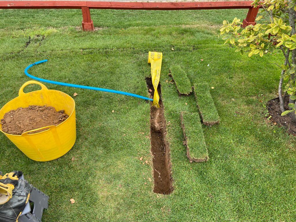
Oh well! My hopes were dashed when the concrete was broken away and I checked the area with the microphone for signs of an audible signal, but nothing.
No choice but to refill the hole and nip out and get some MOT type 1 to get the levels back, once compacted and covered over, nobody would know.
Plan ‘B’
Although the microphone pick up the ‘Thumper’ hydraulic pulses, I decided to build a ‘Pipe Knocker’ which simply hits the pipe using the same controller as the ‘Thumper’ to control a small solenoid, this will be attached directly onto the pipe from the meter.
My idea is that should allow me to hear a stronger pulse working from the meter to the house, rather than from the house to the meter.
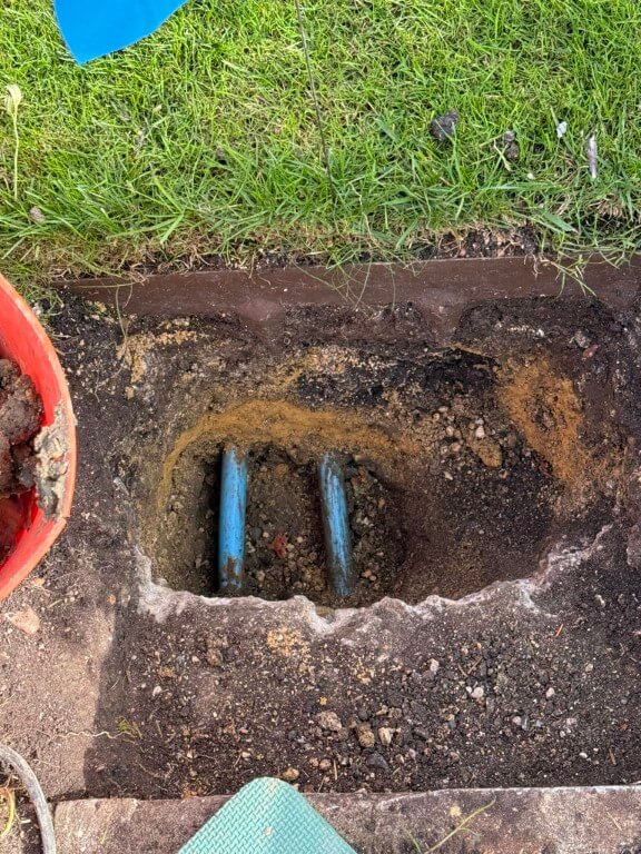
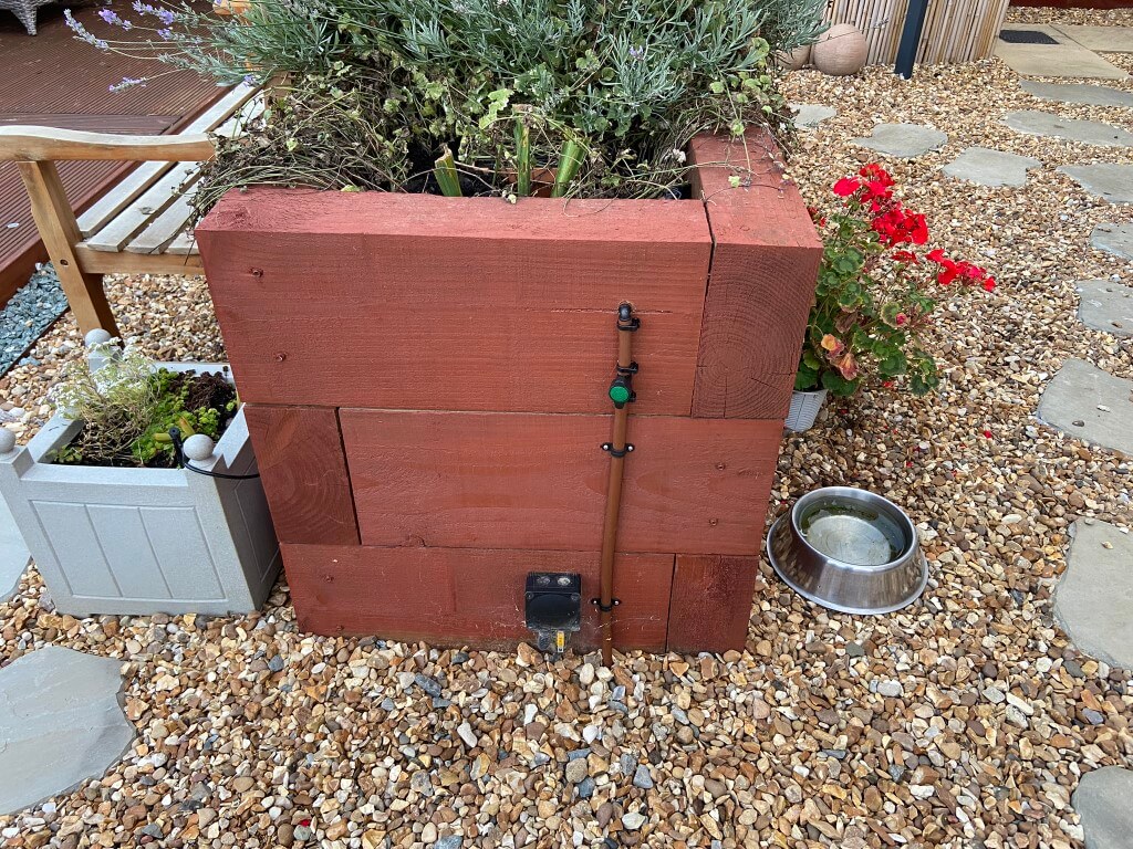
My 25mm feed is on the left and my neighbours is on the right, both directly buried at a depth of 400mm and protected with a layer of sand, I think that due to the close proximity to each other, its not going to be easy to be sure which pipe I’m tracing which ever method I use.
The nuclear and last option will be to expose more of the pipe and cut the pipe to insert a wire with an imposed signal on it that can be accurately tracked by radio detection, giving me a definitive location to dig.
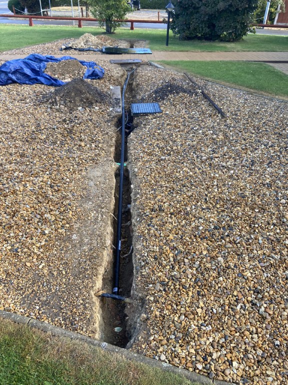
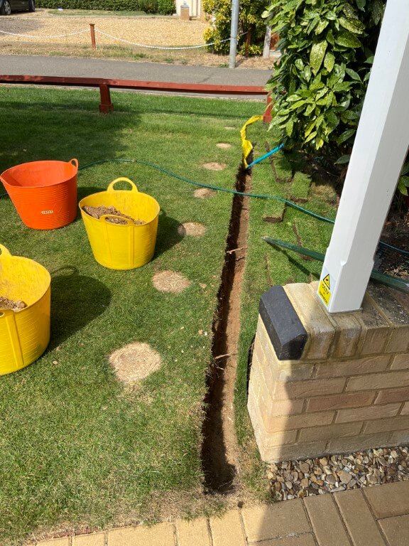
Day 5 – Dig (22 Oct 25)
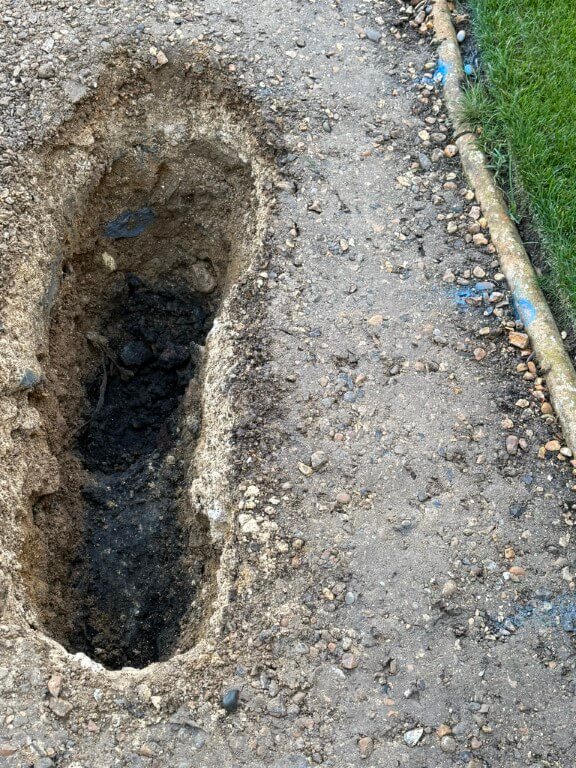
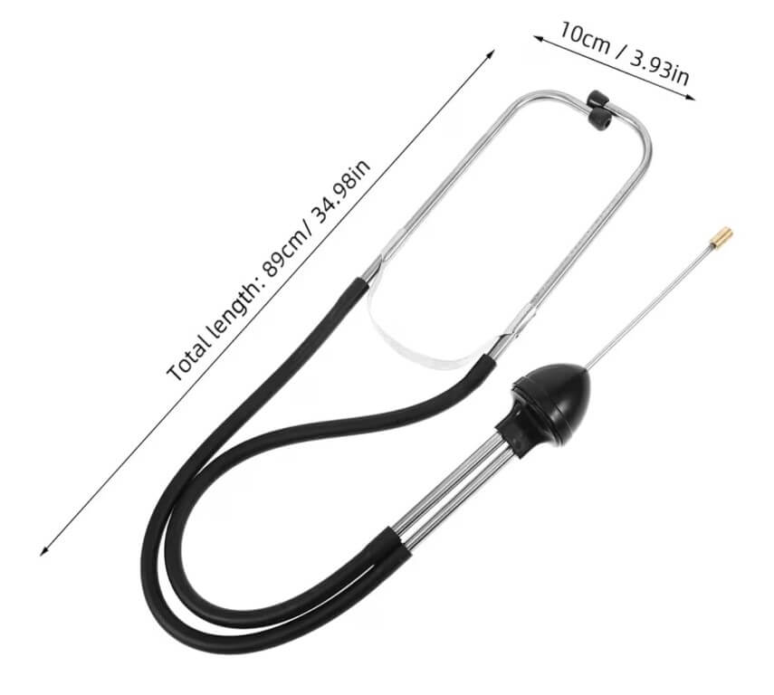
Bit more digging to break out the concrete giving greater access to the water pipe, this is in preparation to cut the pipe and use trace equipment to find the pipes route.
I tried the stethoscope from Amazon to listen for the ‘Thumper’ bit it didn’t work effectively for this application, there was a faint noise, but this soon disappeared as I moved further into the lawn from the meter and the main problem with the high sensitivity microphone was determining any form of direction as the sound generated from the ‘Thumper’ is omnidirectional, therefore, I abandoned the ‘Pipe Knocker’ idea.
Screenshot
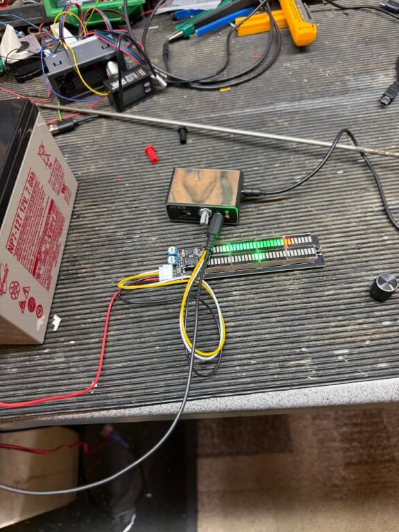
Last ditch attempt was to install an LED bar graph on the audio output of the microphones output.
The idea was to give me a visual indication of the strength of sound received by the microphone and enable me to ‘hone’ in the pipes route, alas this failed as the voltage changes to the bar graph were indicated fine for large vibrations but not with the low vibration signals.
Day 6 – (24 Oct 25)
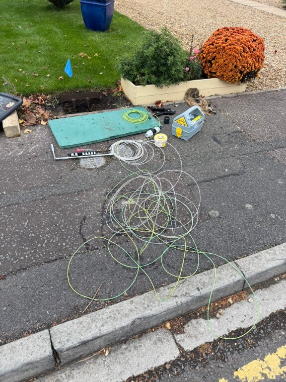
Ok, I admit defeat, I’ve hired the following equipment from HSS:
1 – Cobra with a single core wire tracer which I will attach the cobra, this will be inserted inside the open end of my 25mm water pipe and enable detection of pipe route and depth by the C.A.T.4+
70715 Duct Rod
2 – C.A.T 4+ radio detection device, tuned to the Genny frequency this device will determine the location and depth of the wire tracer within the plastic pipe.
49522 CAT4+
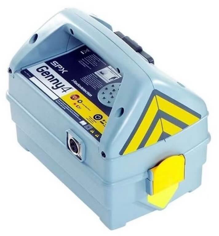
3 – Genny4 transmitter imposes a radio frequency on the tracer wire suitable for the C.A.T. 4+ to detect.
49523 Genny4
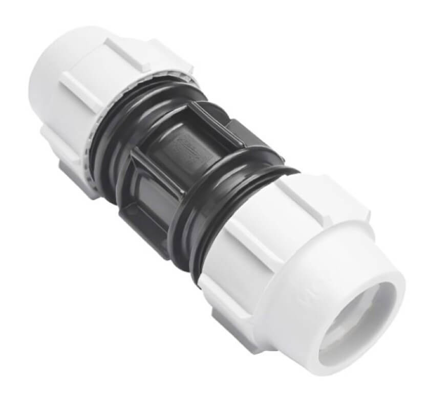
4 – I used Amazon to get a WRAS approved direct bury suitable Plasson 25mm Slip Coupling, this will be used to join the MDPE water pipe where it will be cut to allow the cobra and tracer wire to enter the pipe, a slip coupling will be used as pipe movement is restricted, being fixed points at each end. Another plus to a slip coupling is that pipe inserts are not required, so water flow will not be impacted by any restrictions caused by the coupling.
Day 7 – (27 Oct 25)
I don’t think HSS could have cocked this up any better, the whole experience was a pain in the arse, moving on…..
Cutting a long story short the depth of the water pipe at my preferred sub meter location was ~1.5m deep, so no wonder I could find it with my 800mm trench and water dowsing was a right bum steer!
Breaking this down:
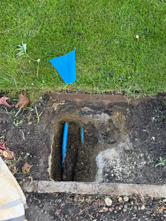
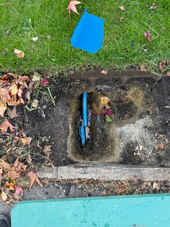
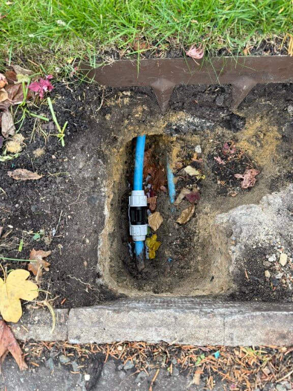
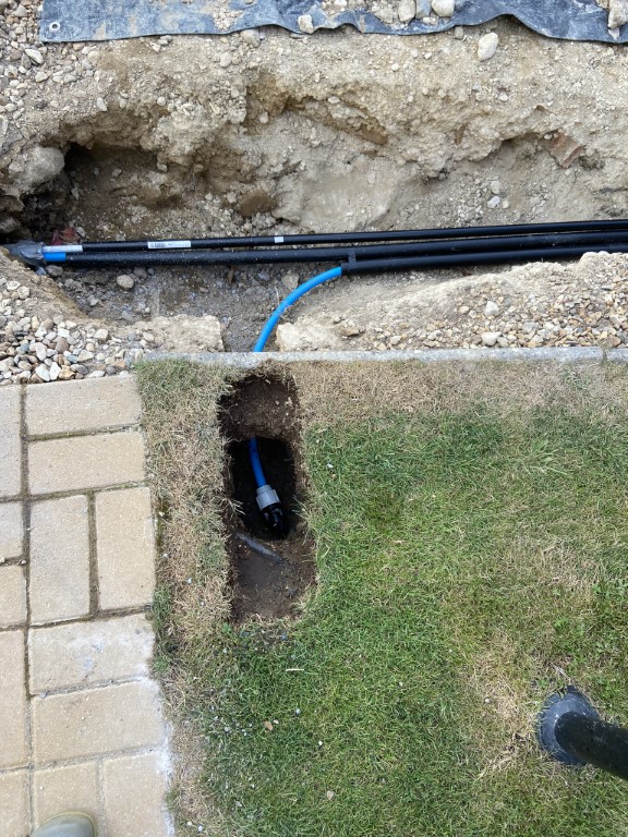
The slip coupling length was marked on the pipe before cutting after I had double checked I was on the correct pipe, the house stop cock was off and that the streets isolation valve was holding.
I decided against using the hired duct rod (Cobra) until I had tried using a plastic conduit fish tape with a wire attached to push deep into the pipe, this worked effectively with little resistance.
Once sufficient wire was pushed into the pipe to where I would prefer the chamber for the sub meter to go, I attached the Genny4 and with the CAT4+, I traced the route and approximate depth of the detected wire inside the pipe.
Slip coupling installed and leak tested.
So that’s the end of this blog on finding a plastic water pipe, as you can see I tried a number of different non invasive techniques, but in the end a CAT and Genny was the only way.
The follow on from this blog is one about installing my sub meter and can be found HERE.
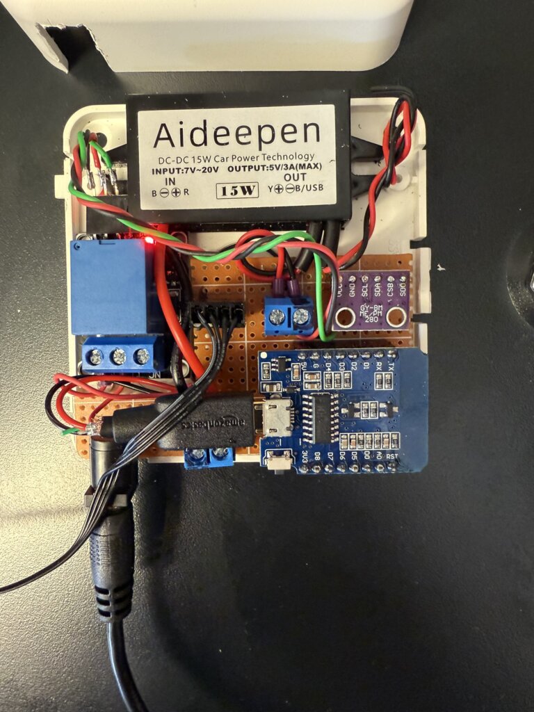
I follow ‘Speak to the Geek’ on YouTube and one of his projects was to control the speed of a fan based on temperature, this blog is how mine ended up.
Full credit goes to ‘Speak to the Geek’ and his homepage where a full description of parts and build are HERE.
The reason this tweaked my interest was to try and maintain a steady temperature in my home IT cabinet and it works with Home Assistant.
My current cooling arrangement has fans which simply trigger on high temperature, hopefully this will smooth out the ‘on – offs’.
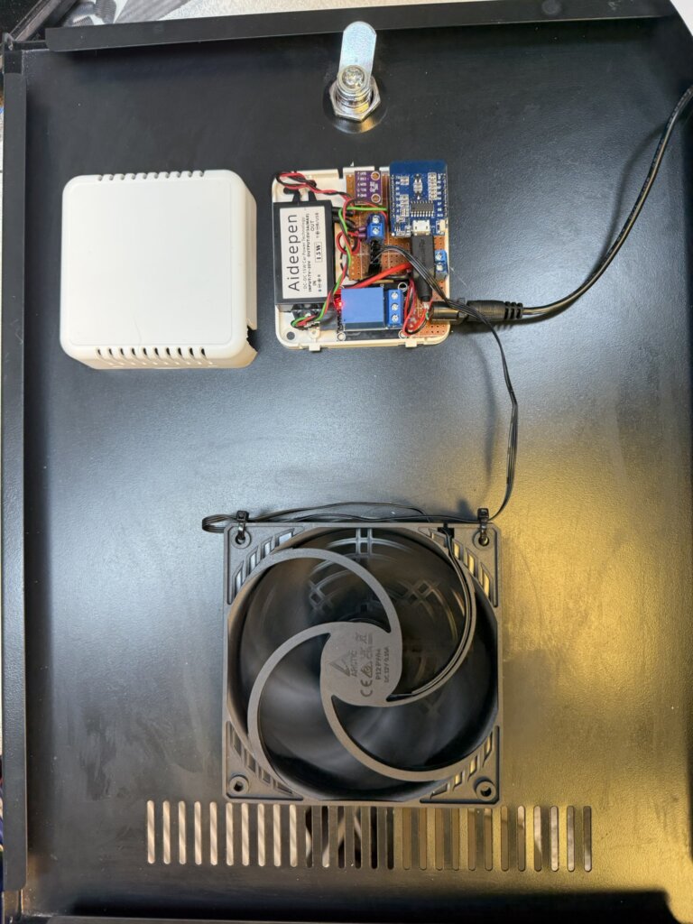
I had a spare ‘Room Sensor Enclosure‘ which I bought from The Pi Hut which everything managed to fit inside.
The 120mm fan will turn on at 28oC at a preconfigured speed of 25%, as the temperature increases, so will the fan speed, reaching full speed at 31oC.
I have a automatic filling water bowl for the dog community in the area which is very popular, (Facebook Link), the water is fed by an 8mm pipe to the bowls float system and works really well, the problem I’m trying to stop is excessive water use, typically if the filling feed pipe becomes detached and goes unnoticed leading to wasting water.
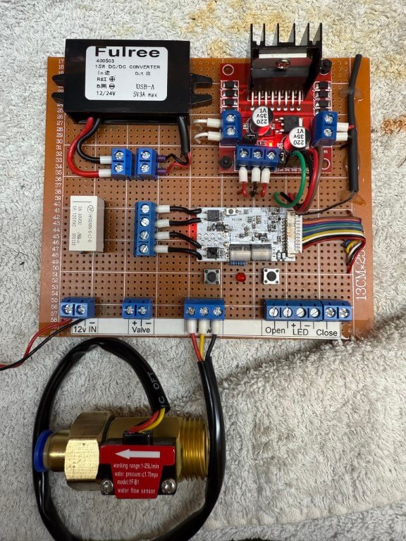
My idea is to use a latching solenoid valve and flow meter linked to a Shelly Uni Plus with automation controlled by Home Assistant.
In normal operation the valve would be open and the flow to the bowl monitored, (the bowl takes 2.8 litres to fill from empty), should the flow exceed 5 litres, indicating excessive use, the solenoid valve will be pulsed by the Shelly Uni Plus and the flow turned off, if this occurs a message will be sent to my mobile.
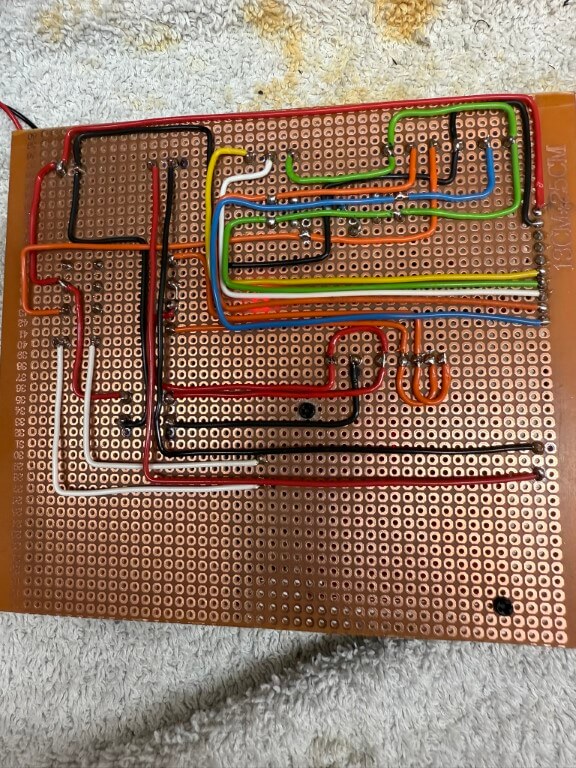
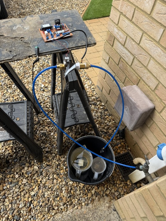
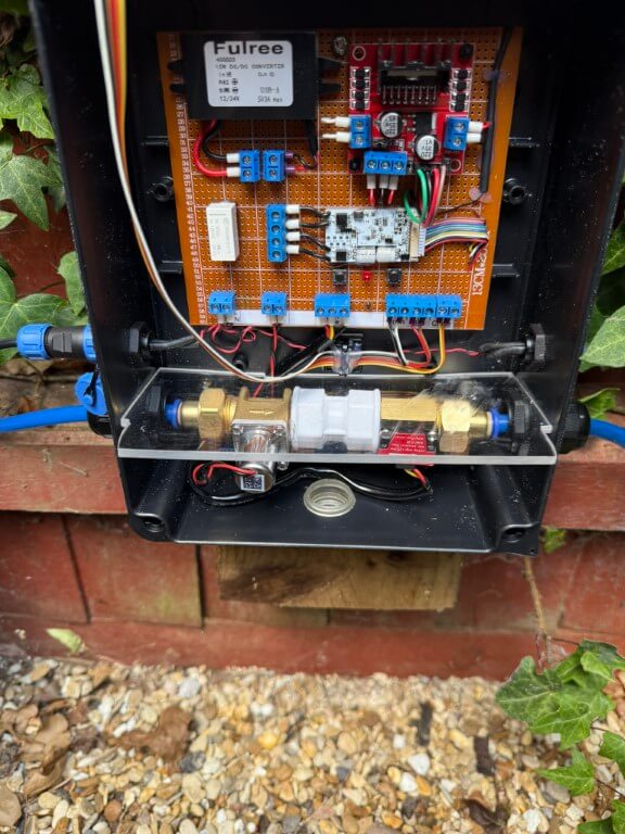
Water controller on bench testing.
Underside of the controller board. 28 July 25, flow sensor 5v derived from the DC/DC converter directly.
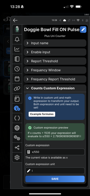
The flow sensor used is a YF-B1 bought from Aliexpress, the instructions said that 660 pulses = 1 litre, to calibrate this for the doggie bowl, I measured 2.8L into a bucket and the count was 1535, adjusting the expression value to x/550 until it read 2.79l, which is near enough!
The Shelly Uni Plus requires an ‘active low level’ pulse to trigger to register a count, the user guide quotes a trigger voltage of 1.5v, the flow sensor is powered from the 5v side of the DC/DC converter and works fine on the test rig.
Test setup with mains pressure water feeding into the solenoid in the open state but with the valve at the end of the pipe closed, once all previous counts on the shelly were reset to zero, I opened the manual valve and filled the measuring jugs (2.8l), this gave me the counts recorded value.
Front cover laminated and stuck on with double-sided tape, all holes sealed with silicone sealant to try and keep the lamination in tact.
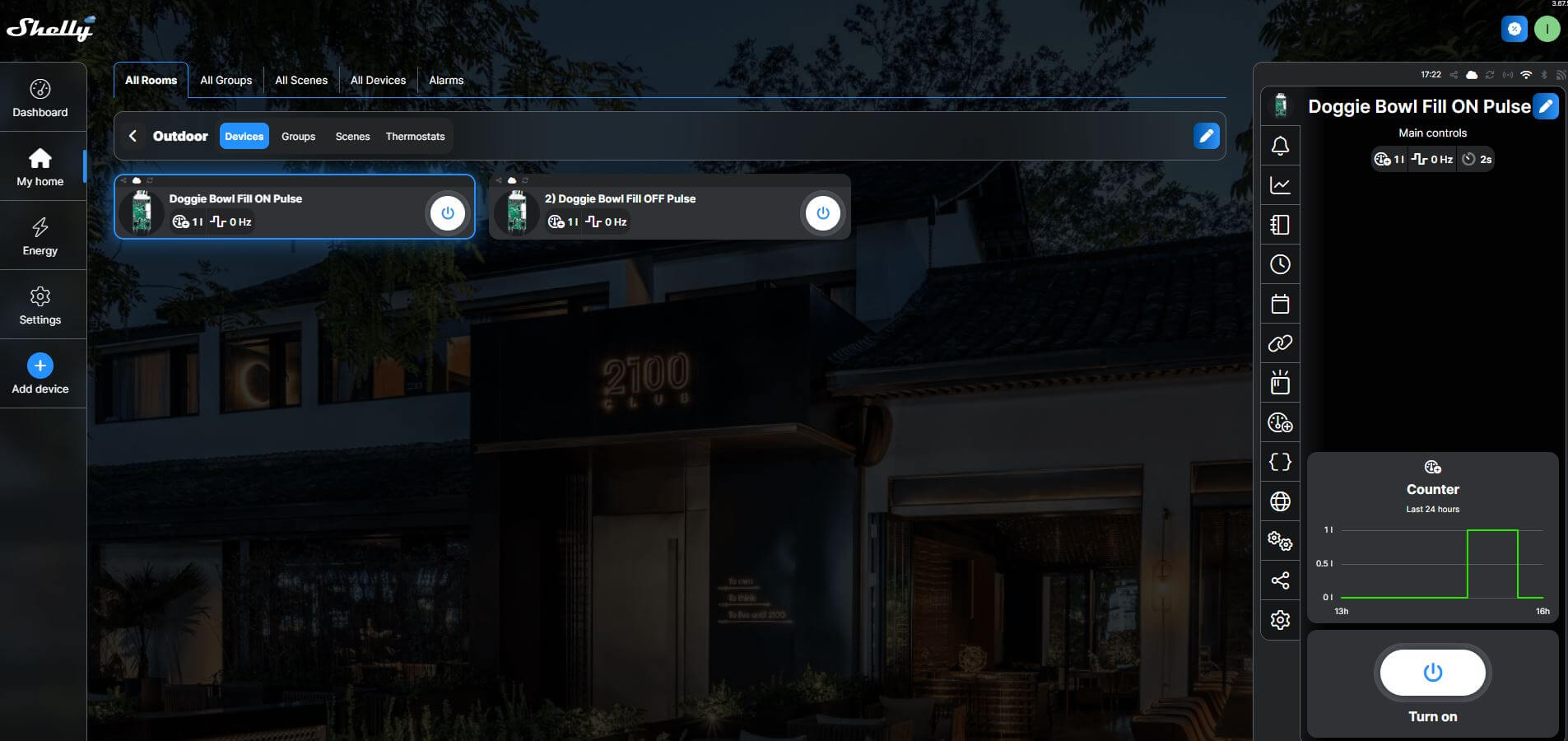
The above is a screenshot of the Shelly Cloud website displaying my Shelly Uni Plus, the ‘Count’ input was used for the flow meter and each of the two Shelly outputs were assigned as ‘ON’ Pulse and ‘OFF’ Pulse.
The latching solenoid valve requires a 30 millisecond pulse of 5v to latch open, reversing the polarity and applying another 30 millisecond pulse will close the valve, the Shelly has this feature built in.
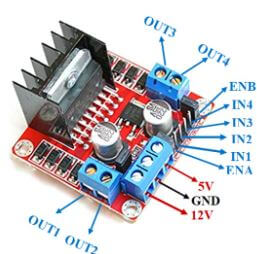
The L298N was fed with 5v with the switching inputs going to pins IN1 & IN2, (IN1 & IN3 linked as were IN2 & IN4), this was done to get two mirrored outputs from the L298N.
One of the 5v pulsed outputs from the L298N goes to a latching relay, this enables a visual indication of the status of the solenoid valve via an LED, whilst the other 5v pulsed output goes directly to the solenoid valve.
Automation
Within the Shelly App is ‘Counts Custom Expression’ which for my flow meter is x/550 with the expression unit being l (litres) for a volume of 2.8L which is a complete refill of the doggie bowl.
Home Assistant integrates with Shelly and shows the counter as either a counter value in Litres (set up above), and actual pulses recorded, both of these are cumulative values.
For my purposes I want the open solenoid fill valve to close once 5 litres have pasted through the flow meter in 24 hrs, indicating excessive use.
In order to get the counter value to reset at midnight, I used a Helper and defined the counter entity as a Utility-Meter with a daily reset time and renamed this as Bowl Water Used.
Within Automations, the rule is –
When Bowl Water Used is above 5 litres
Then Turn Off fill bowl & send mobile notification
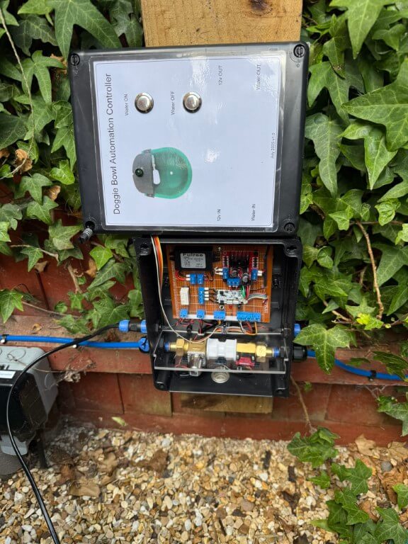
Completed Project
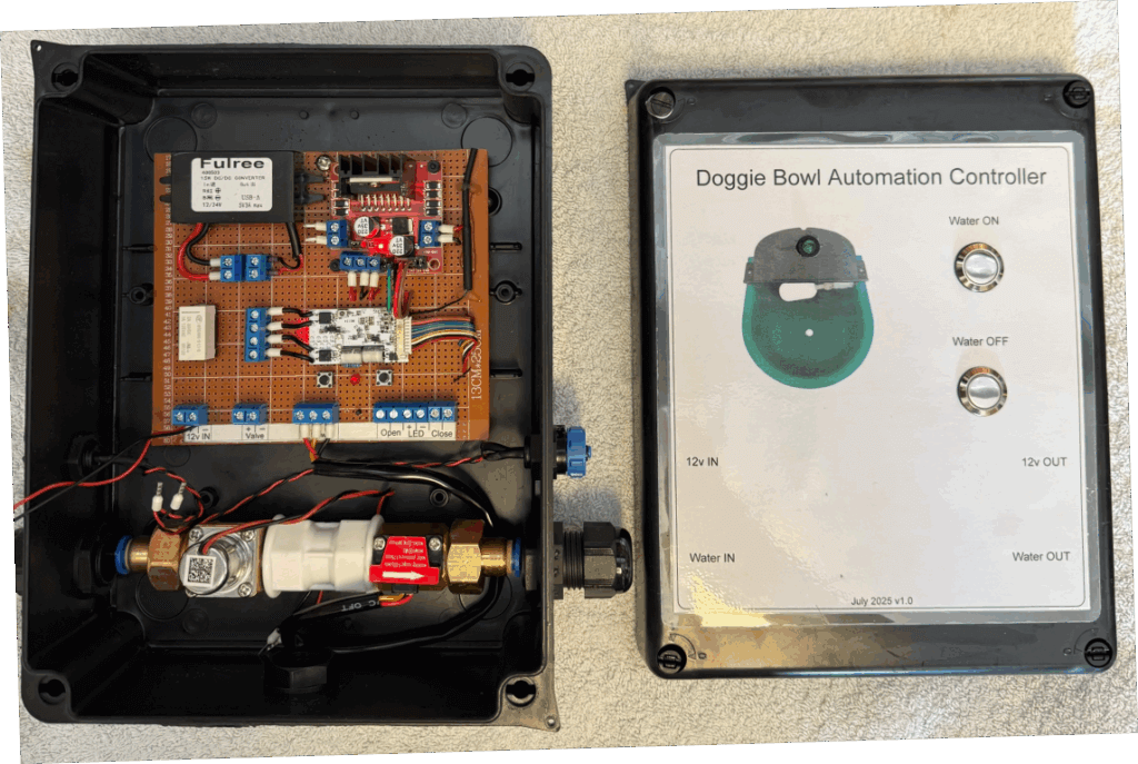
Unit plumbed in and 12v power getting connected, another 12v connection is opposite the inlet for future use.
I fitted a perspex divider between the water side and electronics to reduce any damage in the event of a leak, if any water does accumulate, the box has drain holes drilled in the rear of the box and a ‘tell tail’ clear grommet.
Green LED indicates if solenoid valve is latched open, local control of the valve is via the pushbuttons. On the feedpipe to the doggie bowl a drain down/test point is fitted.
To limit rain getting on the control box, I’ve made a small wooden overhang, the enclosure is IP65 rated but I’m trying to keep water from getting into the laminated front panel details.
My Home Assistant display shows the valve position and water used, it is also possible to manually operate the solenoid valve from the dashboard.
Observation
When I emptied the bowl to clean it, the float valve operates to refill the bowl, however, water volume recording is ‘hit and miss’, I’m putting this down to the bowls float valve not being fully open, restricting the flow volume though the sensor leading to detection errors, however, opening the test point into a bucket at full bore, approximately 6 liters flows before the automation closes the solenoid valve to prevent water being wasted which is the main function of this project.
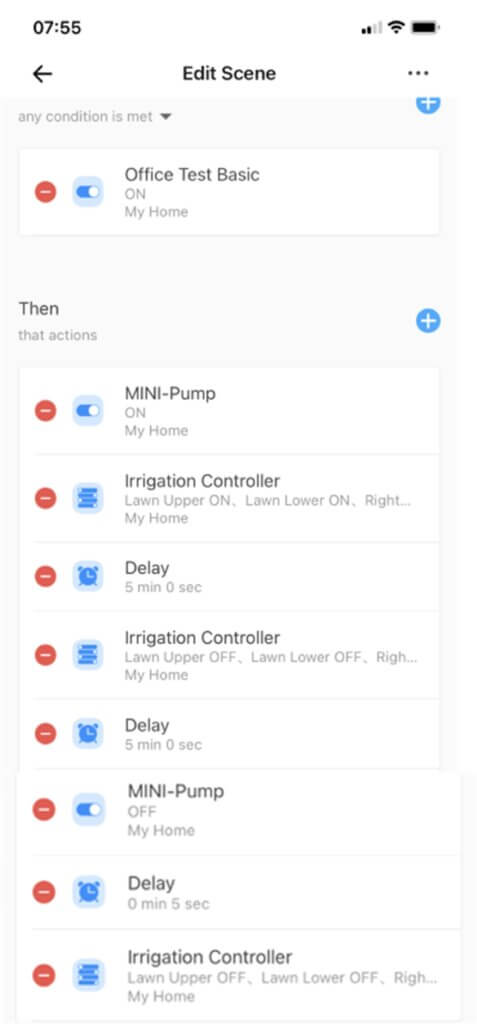
My existing Sonoff watering control comprises of a Sonoff Basic to turn the irrigation pump ON/OFF and a Sonoff 4 Channel Pro which controls which set of lawn valves to Open/Close.
My existing setup had an automatic scene to water the lawn when the grass had established, however, I wanted a Scene to automatically run for a newly seeded lawn which just kept the seed moist by frequent watering, but short in duration so as not to wash the seed away.
My existing system has a Rain Sensor, so if it has already rained, the scene would still run, but the power supply to the irrigation pump is removed until the rains sensor is happy.
List of Requirements:
Water the lawn every 3 hours
Start watering at 06:00
Stop watering at 20:30
Sprinkler duration 5 minutes
How:
I had to use another Sonoff Basic as a Smart Device trigger to start the irrigation scene.
Triggering Basic device setup to have ‘Inching’ enabled with a short duration ‘ON’ time
Set up a schedule to turn the Basic on at the required times, (no OFF time is required as the Basic is in inching mode)
Turn the Basic schedule ON and save
Create a new Scene
Set the IF action trigger to be the Smart Device Basic
Set the THEN actions
In my scene, the following happens:
Scene triggered by the Basic switching at the scheduled time
Then, irrigation pump turns on
And, the Irrigation Controller (4 channel Pro) switches power to Open sprinkler valves on two sections of my lawn
after a 5 minute delay the Irrigation Controller closes the two valves and opens another lawn areas valve
after a further 5 minute delay, the irrigation pump turns off
5 seconds after the pump turns off, the irrigation controller closes all the valves (delayed to allow the water pressure to fall)
I had help with this from the eWeLink & Sonoff User Group on Facebook and in particular Stipan Retkovac who has extensive knowledge in this area and to whom I particularly grateful.
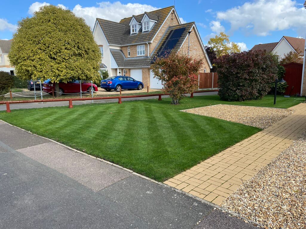
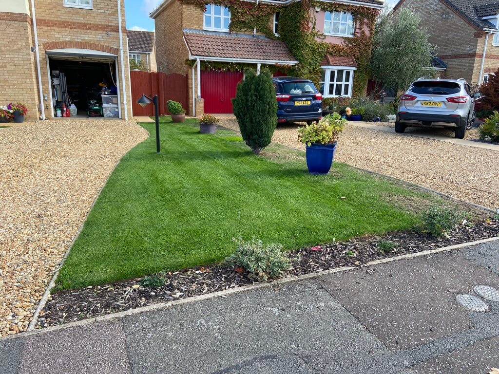
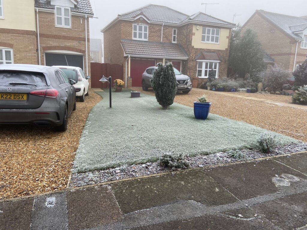
In 2022 I decided to invest some time and effort in getting the lawn in shape after years of neglect, so I followed a number of lawncare YouTubers, and with their advice, the lawn has never looked better even in winter.
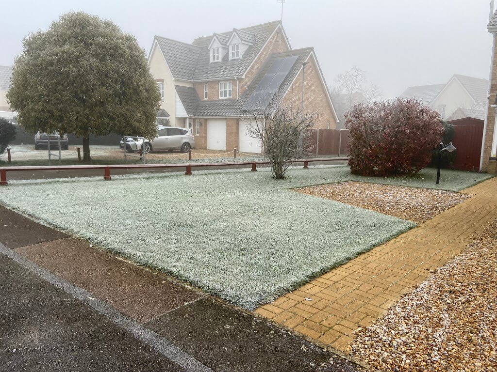
11/12/22 -4.2c
11/12/22 -4.2c
Unfortunately July 2022 was the hottest (currently) temperature ever recorded in the UK, and lawn watering was needed to keep the lawns (total area 117m2) in good shape, this took ages to do as my mains water pressure is poor and I have three separate sections of lawn, so the idea of an irrigation system tailored to my lawn layout was formed, I did have some experience, as I installed a simple Gardina pop-up sprinkler system at my last house in 1997, the difference being that the pipes were laid before the topsoil for the lawn.
I jumped back onto YouTube to start learning about irrigation system technicalities, and this blog is about how I installed my system.
Safety before you dig
As the irrigation pipes in my system needed to be buried rather than an above ground system and I’m digging near the pavement , I checked with Line Search before starting any works. This is a free online service, using this portal enables multiple interested parties to let you know if they have a pipe or cable near where you are working.
Not all companies are signed up to Line Search and during my hand digging I did exposed an Openreach telephone duct just inside my boundary which I did not expect!
Line Search did identify close proximity to Gas and Electricity services:
Anglian Water and Virgin Media services are also on my property but not identified by Line Search, I did make sure I knew the path these took before digging.
Irrigation Design
Fortunately a lot of information is readily available on the internet from manufactures, the two key players seem to be RainBird and Hunter, I downloaded the Hunter guide, so it made sense for me to deign around the guide and use their products.
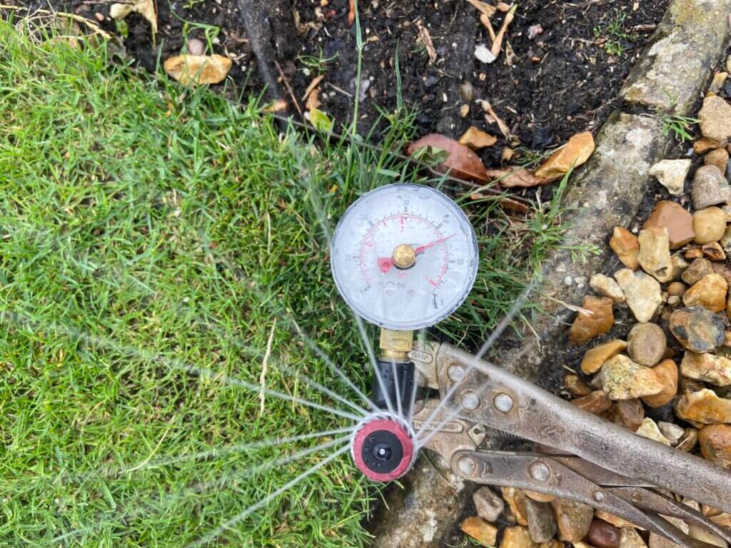
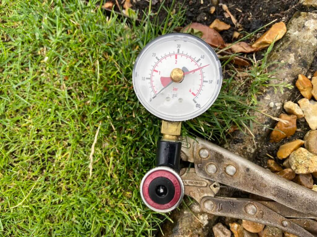
Following the guide, I needed to find out was the static water pressure and water flow rate available to me, using a Toolstation pressure gauge connected to the outside tap which is fed directly of the incoming rising water main, here I recorded a spot reading of 2.7bar (40psi).
Chatteris is at the end of the water supply pipeline and the pressure can get quite low at times depending on upstream demand.
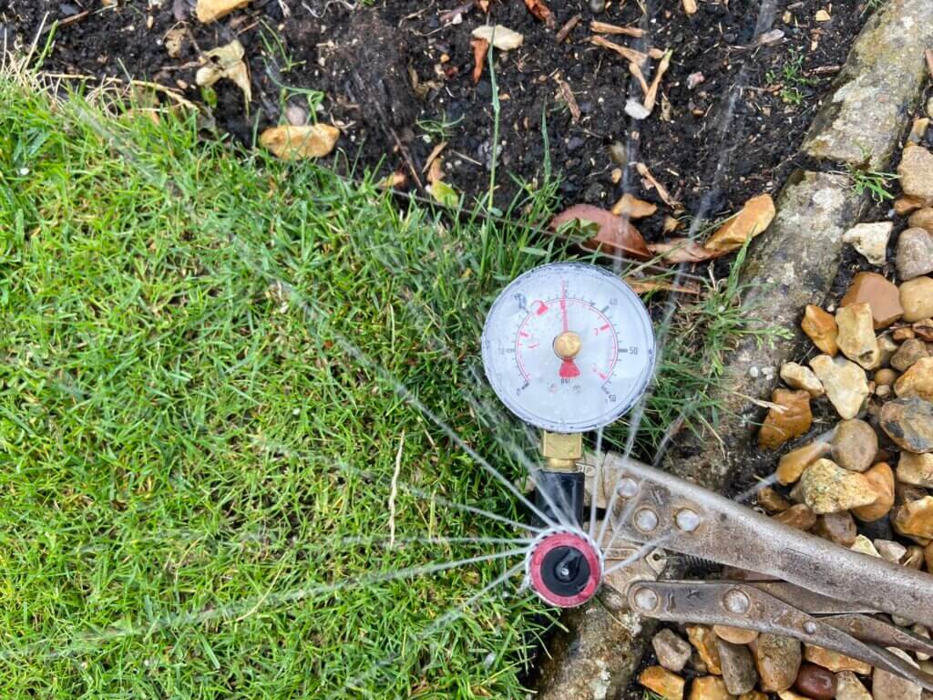
Flow rate was also measured at the outside tap, the flow rate was calculated at approximately 35 litres per minute, (timed bucket method, (I did confirm this later using a weir cup).
A quick glance at the Hunter products indicate that the optimal water pressure is 2.8 bar at the sprinkler head, therefore, I knew I would have to use a break-tank and pump to give me assured operation without dependency on the incoming water pressure.
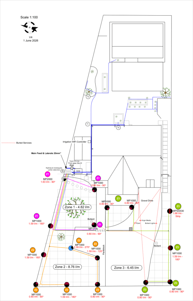
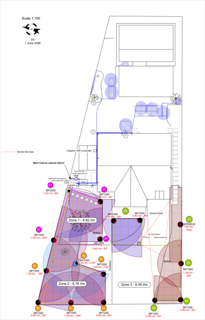
Using Visio, I drew out a scaled drawing of the house and garden in order to work out the spray head coverage, pipe runs including pipe lengths and types of fittings needed.
It is important to work out pipe friction losses so that the pipes used are not undersized which would give an unacceptable pressure drop at the furthest sprinkler head, another consideration is water storage, you can’t connect a booster pump to an outside tap, if you have a stream, that’s perfect.
Digging Plan showing pipe routes, head placement and predicted water consumption, a full parts list can be extracted from this.
Drawing showing scaled spray coverage pattern confirming head types.
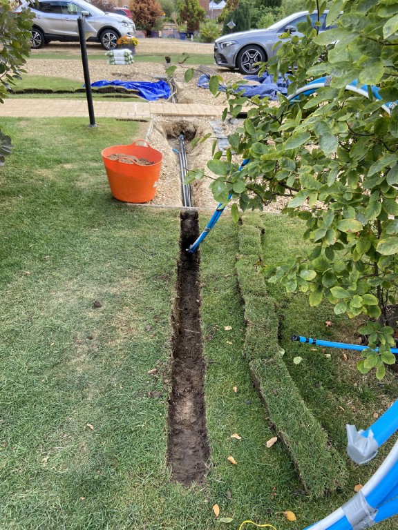
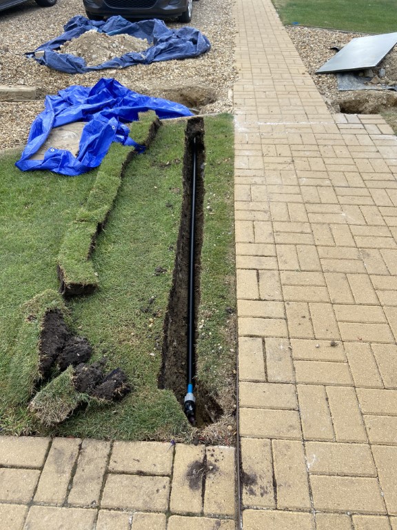
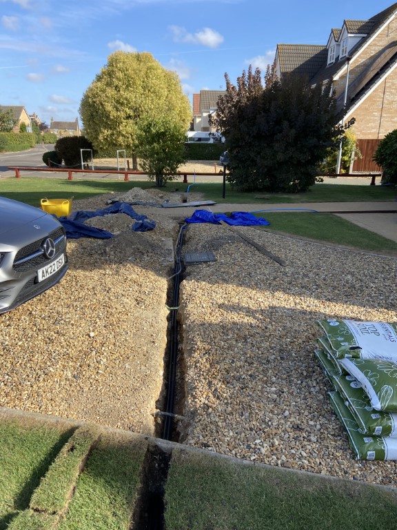
Drive dig underway, to Zone 3, the 20mm water pipe will be inside a 32mm duct (waste piping).
Digging Method: I first marked the sprinkler head locations on the lawn with a blue spray in positions from the dimensioned drawing, using string as a straight line to follow, the Lawn Edging Knife was used to cut a section of lawn approximately 12cm wide by 14cm long (4.3/4″x 14″), using the trenching shovel to get under the cut grass and levering it out for replacement later.
The width of the trenching shovel is 10cm (4″) about the same as the width of my boot which is handy for compacting the sand and soil later.
The depth of the trenching shovel is 20cm (8″) which in my case is adequate as water will be removed from the pipework over winter and also my aerators hollow tines are 12.5cm (5″) in length so I should avoid damaging the pipes when I aerate.
The builders left all sorts of bricks and debris everywhere before they put a layer of soil on top for the lawn, this made digging very difficult in places and the crowbar was superb in making a hard job easier.
Once the trench was cleared of stones and the trench bed flat, a layer of sharp sand was added to bed the pipe on, the pipe, even thought it was only 20mm needed pining down with stakes to keep it straight, a second layer of sharp sand was put on top of the pipe, then a marker warning tape followed by a bit more sharp sand, all compressed at each stage by a size 9 boot.
I used Levingtons essential top soil to fill the remaining trench, the first layer is compressed well down, the second and final layer is loosely laid so that when I place the cut turf back and ‘persuaded’ it down with the back of my shovel, the soil has somewhere to go.
When the turf was re-laid a sprinkling of top soil was added to fill the joins and brushed in, then liberally watered.
The tools used to dig were :
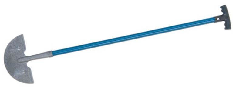
Silverline lawn edging knife
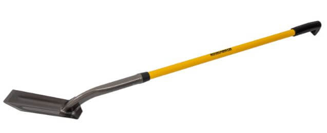
Roughneck trenching shovel 48″ from Toolstation – code 57538
Bulldog chisel and point crowbar, model 60-BCB60CP from Travis Perkins.
Above images are after a month of the sprinkler feed pipes being buried, showing just how resilient grass is.
Break-Tank & Pump
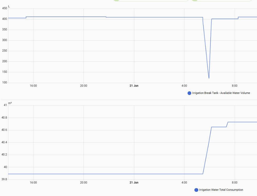
The volume of water storage available to you influences how many sprinkler heads you can have on at any one time and for how long before the the pump runs dry as it draws out more water than you are capable of putting back in it, this is a key limiting consideration for a watering schedule as a tank recovery time must be factored in.
The above graphs show Break-Tank water 30 minute watering cycle depletion and water filling volume during one irrigation cycles, as you can see, if I’d increased the watering cycle to, say, 45 minutes, the amount taken from the tank would exceed the tanks filling rate and the tanks low level detection would operate, stopping the pump.
A way to irrigate for longer periods whilst maintaining a working tank water level is to not have all watering zones on at the same time in my case, matching the water top-up with water draw.
The tank used is a Wydale Plastics 500 litre capacity upright water tank bought from Facebook Marketplace for £40 , this is perfect as my break-tank.
The term break-tank means their is no direct connection to the incoming water supply, the water filling float valve is positioned to maintain an air gap to eliminate any back-syphoning cross-contamination risks with the incoming drinking water supply, the height of the float valve within the tank, has reduced its capacity to approximately 430 litres.
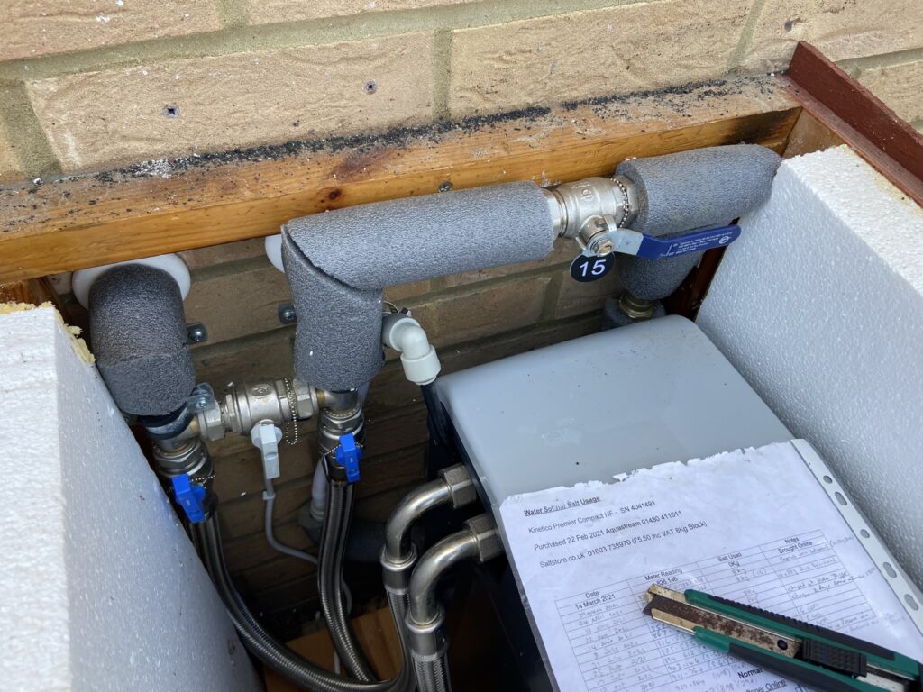
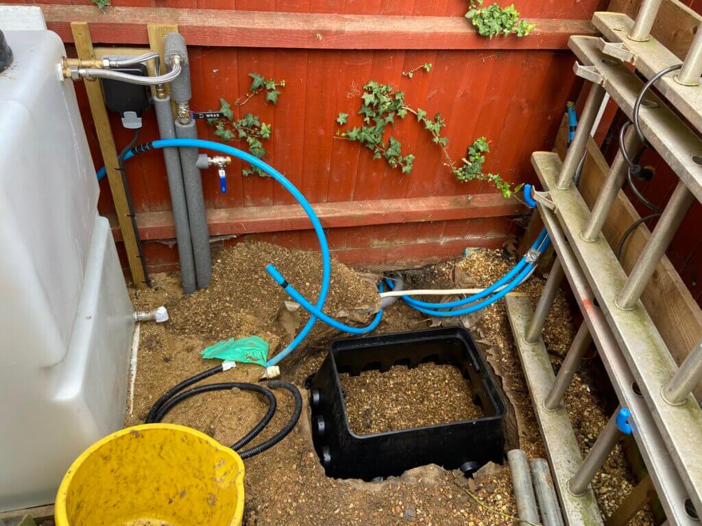
On my system, the break-tank can be filled in two ways, the primary method is via an independently metered 22mm supply from the incoming rising main to the 3/4″ float valve on the break-tank, this feed has a full bore isolating valve, double check valve and drain valve in-line for maintenance.
Valve 15 is the 22mm feed to the break-tank.
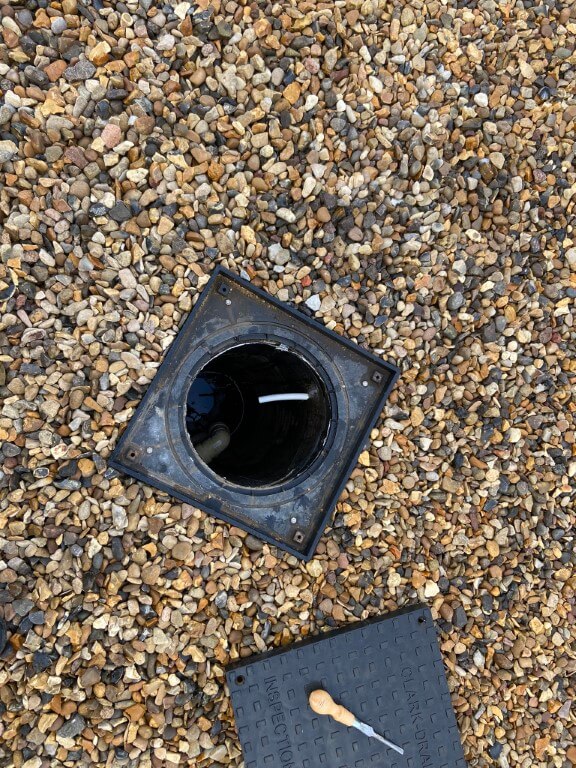
The second means of filling is by using the break-tank overflow line in reverse and pump the vehicle inspection pit water through this, (white 15mm pipe) via a ‘Y’ strainer at the tank end, in normal use, the break-tank overflow is into the pit.
Break-tank overflow into vehicle inspection pit, the pit holds 5,643 litres (1,241gallons), so very useful storage for pumping back to the break-tank, the grey pipe is from my gutters so I can harvest rain water.
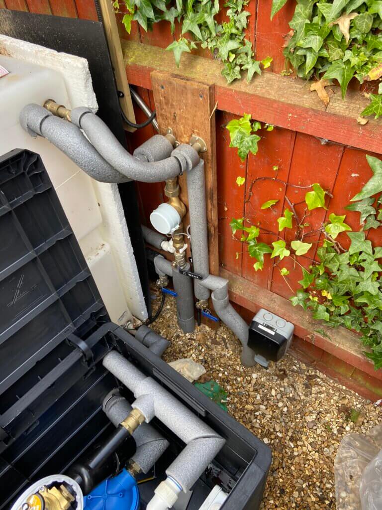
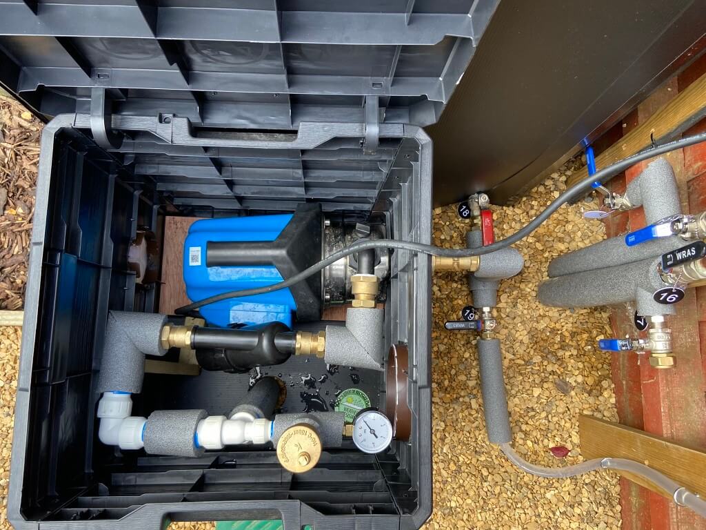
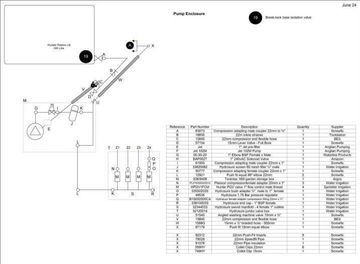
Break-tank in position sitting on 25mm polystyrene sheeting and plumbed in. Water is metered and electronically recorded.
At the base of the break-tank is a 3/4″ full bore lever valve feeding a 22mm pipe with a 80 mesh ‘Y’ strainer fitted, the connection from the ‘Y’ filter to the pump suction line is with a 1″ flexible hose, connection to the pre-filer from the suction line is with a 1″ to 22mm adapting coupler (Screwfix 61955) .
The pre-filter is a Clarke PF1, 5 micron filter and comes with bowl removal spanner, the filters 1″ BSP pitch’s is quite course so a good sealant is required, I used a combination of PTFE tape and pipe thread seal (Screwfix 4373J).
I understand from Machine Mart who sell the Clarke pre-filter that replacement filter elements cannot be supplied.
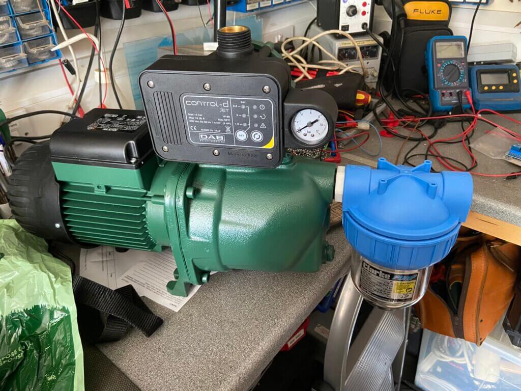
Due to inadvertent prolonged running of the Clarke SPE1200SS original pump and its subsequent damage, I decided to ‘bite the bullet’ and buy the pump I should have got first time round!
Anglian Pumping supplied a DAB Jet 102M with a maximum 6bar delivery pressure (87psi), referring to the data sheet this will give enough pressure to operate all the sprinklers at the same time, something the Clarke SPE1200SS didn’t have capacity for.
In order to prevent the same scenario which caused the failure of the Clarke SPE1200SS from happening with the JET 102M, I bought a DAB-G-SET controller, this stops the pump if it detects dry running or seizure.
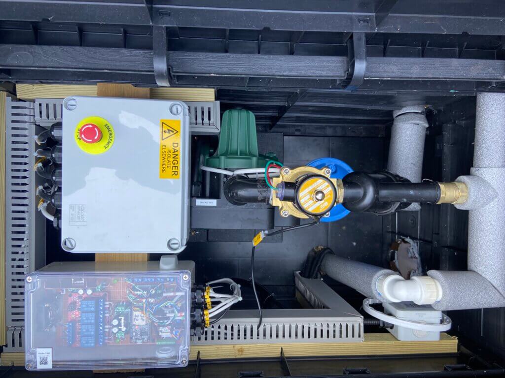
After the pump delivery is a 1″ solenoid valve which is normally closed, then an 80 mesh inline filter before the zone valve manifold.
The solenoid valve acts as a main valve before filter and sprinkler valve manifold, with the solenoid valve closed, the pump will run-on until the water pressure reaches 1.5bar, at which point it stops.
When a signal is sent to open the solenoid valve and then the sprinkler zones valves, the pump controller will register to drop in water pressure and turn the pump on until all the valves are closed.
With all valves closed, the pump will run-on slightly to reach 1.5bar and stop, ready for the next watering sequence.
To eliminate sunlight getting to the break-tank in order to stop water borne algae growth which will eventually block the water filters, I decided at this point to insulate the break-tank even though it will be empty over winter.
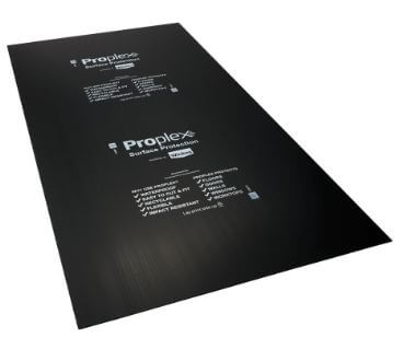
I used 25mm polystyrene sheets to insulate the break-tank and to weatherproof this, I used black opaque floor protective sheets from Wickes which was perfect all held together with Lidl black duct tape:
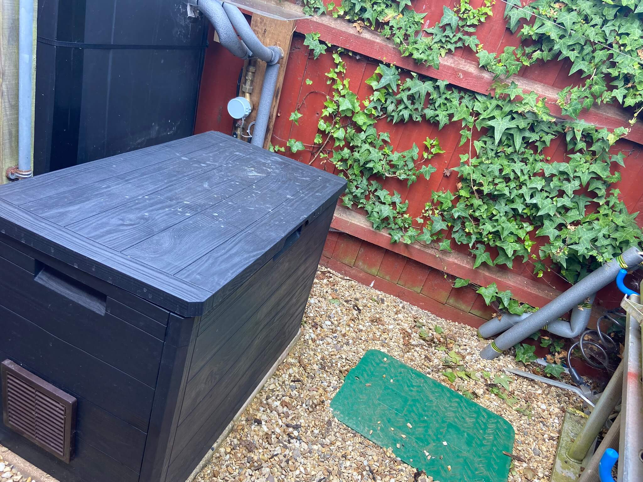
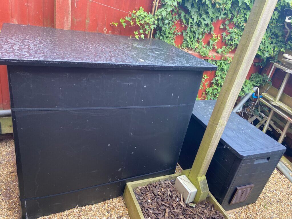
Pump positioned inside an Argos Toolmax 160L Patio and Balcony Chest 326/9408 to keep it out of the elements, ventilation grills and temperature monitoring fitted.
In a ‘Normal’ setup, the pump is connected to a plug via the pump controller and that’s it, however, I wanted to monitor and control certain parts of the system using Home Assistant.
Below is an image of the first iteration of the irrigation pumping system before upgrade:
Sprinklers & Water Usage
The sprinkler assembly comprises of the spray body, sprinkler head and a water inlet, I opted for the Hunter PRS40 body with an assortment of MP Spray Rotator heads to suit my application.
The benefit of using PRS40 body is that it has an inbuilt pressure reducing valve giving me flexibility on the pump pressure, the body limits internally the water pressure to the sprinkler head to 2.75 bar (40psi) which correlates to the sprinkler head data for spray patterns and water usage, this means that as long as the water pressure is greater than 2.75bar to the body along the pipe run and at the furthest point, everything should work as designed.
The spray bodies water inlet is a female 1/2″ BSP, in order to connect to the irrigation main line, I used a Sprial Barb fitting – 1/2″ male elbow (Stock Code SF-SBE-050), two are needed, one on the spray body, the other for the 20mm pipe fitting.
A semi-flexible pipe links the spray body and main feed pipe, this pipe is called Swing or Funny Pipe (no idea why!), the code for this is SP30. Part codes used are from Sprinkler Irrigation.
My system uses 15 sprinklers with MP rotators:
1 x MPSS530 – Side Strip pattern
1 x MP2000 – 900 – 2100 pattern
1 x MP1000 – 2100 – 2700 pattern
12 x MP1000 – 900 – 2100 pattern
Water consumption per sprinkler head is dependent on the adjusted coverage pattern, the rotator data sheet enabled me to work out the expected water volume, data also exists on the Growinsane website regarding emitters l/m, again this is dependent on adjusted flow at the specific emitter.
Total front lawn – design usage 19.2 l/m, measured usage 21 l/m
Rear planters and pots – measured @ 16.6 l/m
The Hunter MP Rotator data I used can be found HERE, however, a revised Metric version is HERE.
The rear garden has a number of the following emitters, the l/m value is for each emitter:
I ‘tweak’ and constantly review the ‘run times’ now I understand how effective the sprinkler head patterns are at delivering the required volume of water to the lawn and plants
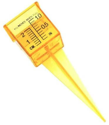
Water gauge from AliExpress – £6.73 for 10.
The volume of water filling the gauge drives the watering run time as I’m looking for an average total of 25mm per week on the lawn, (this is a cumulative total and will include rainfall).
The MP Rotator heads deliver a soft watering pattern to avoid runoff and enable the water to soak in, using water gauges placed at random places across the lawns, the average water collected over a 10 minute cycle was approximately 4mm.
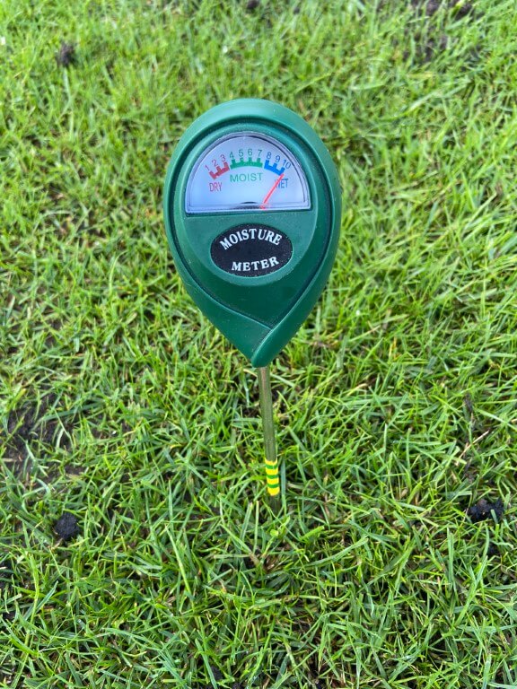
This means that just over an hour of irrigation will give me the weekly total of 25mm, however, I spread the watering periods over early mornings each day as a minimum, if the lawn shows signs of distress, I increase the watering frequency as the whole topic is a ‘black art’ and along as my moisture meter is happy, so am I.
Lawn Watering Cost – Budget for it!!
Updated for 2025Season
The price of 1m3 of water is now £2.68, and I’ve increased my watering cycle to 30 minutes for a deeper watering, using 830 litres each time, adjusting for sewage abatement, the cost per cycle is £2.00.
June has been very warm meaning two cycles per day when its baking hot, costing £28 per week!
Legacy2023 Information
I started a watering schedule in April, this schedule, (duration and frequency), varied based on when I over-seeded and if we have had rain, another consideration was the lack of rain coupled with high temperatures, lots of variables all contributing to evapotranspiration!
The actual cost for running my 15 sprinkler heads for a 117m2 lawn for 10 minutes costs £0.65p per day, this cost is made up of water charges and sewage/foul costs.
To water my lawn for 7 days to give me >25mm costs £4.55 per week.
Where it started to expensive was when it didn’t rain, obvious really :-), Example – June 2023 was a dry, warm month, with only 5mm of rain measured, so with a bit of over-seeding and to keep the rest of the lawn growing, I used 26.8m3 of irrigation water from the 4th June to the 22nd costing £4.54 per day.
The costs used are based on Anglian Water, June 2023 charges, 1m3 (1000 litres) costs £1.68p, add to this the sewage/foul costs which are based on 90% the water used and cost £1.71 per m3.
Update – 2 October 2024
Having taken advantage of the water authorities ‘New Lawn’ allowance before but I didn’t know until a chance conversation that you can request a ‘Sewage Abatement‘ for that does not use the drains, e.g. Irrigation & swimming pools. So instead of a 90% levy, this drops to 10% per 1m3.
I spoke to Anglian Water and they simply record the fact you have called and at the end of the season you let them know how much water you have used on the lawn, I have a sub-meter for my irrigation system, but I double check this against my main meter, once the readings are given to them, they will calculate the rebate.
At the end of the 2023 season I spoke to Anglian Water and my account was credited with £91.66 for irrigation water used, result 🙂
At the end of the 2024 season I spoke to Anglian Water as they still had my usage details, the process was simple and my account was credited with £44.38 for irrigation water used, the two main reasons for the lower cost was I used harvested stored rain water and poor summer.
Update – 24 September 2025
Started irrigating the lawn from the 31st March until 24 September using a total 47m3 of water, Anglian Water abatement refund was £97.01, happy days!
Pipe Sizing
This is probably the most critical element, if any of the pipes are undersized, then the pressure drop at the furthest point may make the system unusable at worst or poor forming at best.
The information I had was, as a rule of thumb, that a 20mm pipe will pass 1000 litres/minute (l/m) and a 25mm pipe will pass 2000 l/m, as I had independent zone control, with the highest water demand zone taking less than 9 l/m, I went with 20mm MDPE pipe as the flow rate, pressure and pipe length all worked out fine for my lawn.
It turns out that the sprinkler head water volume is when the head is at its full design pattern, a number of the heads in my system have had the coverage tailored to my lawn, therefore the water consumption is slightly lower, the DAB Jet 120M allows me to have all 13 sprinklers on at the same time with no adverse effect on water pattern coverage as the pump pressure is healthy.
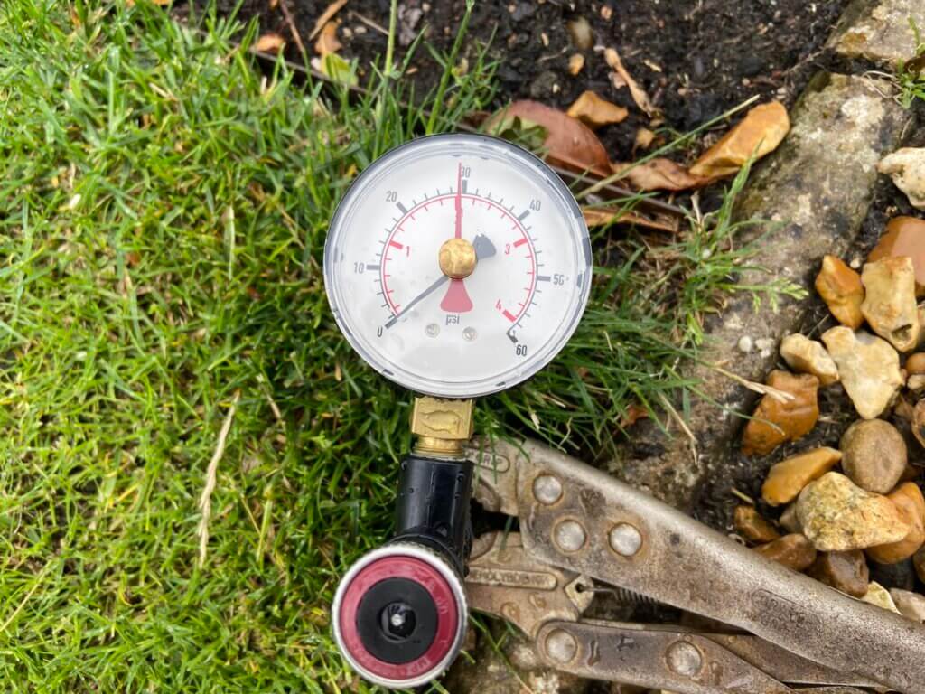
3 Bar
As stated earlier, the Hunter PRS40 bodies have an integral pressure reducing valve so they operate at their optimal water pressure which is 2.75bar (40psi), it is important therefore, that the pressure reaching the spray body is => than 2.75bar.
The above reading of 3bar pressure was with all sprinklers working, if I turned on the rear garden watering line as well, the pressure expectedly dropped and recover to 2bar recovered, however, as this is below the optimal sprinkler pressure, I’ll ensure the sprinkler schedule does not have all four zones on at once.
2 Bar
Pressure readings were taken using a MPADAPTER which allowed me to measure the dynamic pressure reaching the furthest sprinkler heads on each zone, determining if => 2.75bar pressure is being achieved, which it was :-).
The majority of pipe fittings were from waterirrigation, MDPE pipe 20mm compression fittings require pipe liners (inserts), to stop any deformation of the pipe in the fitting, I was told it was ok to omit this, but as the liner are cheap, I didn’t think it was worth the risk of a leaking joint at some point in time.
Getting a clean, square cut on MDPE pipe is important as it gives a good face for the liners lip to sit against and also it makes insertion past the fittings ‘O’ ring easier with a reduced chance of seal damage, to get a clean cut I used pipe shears from Lidl for £9.99.
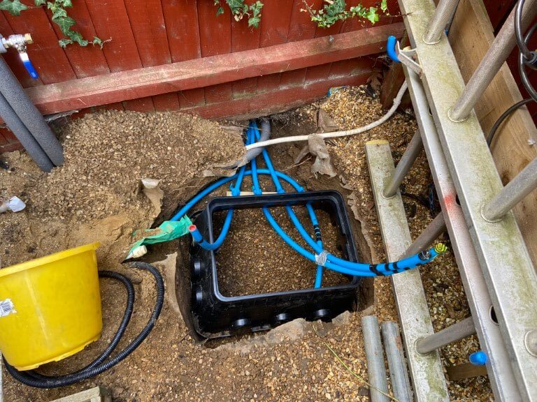
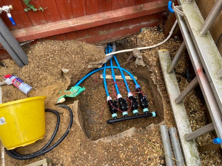
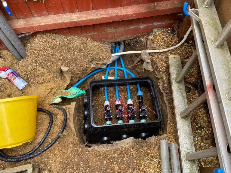
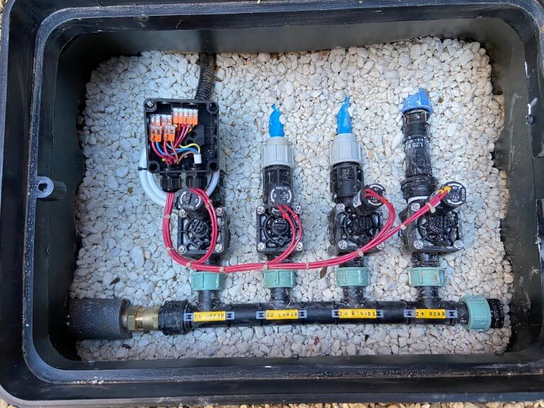
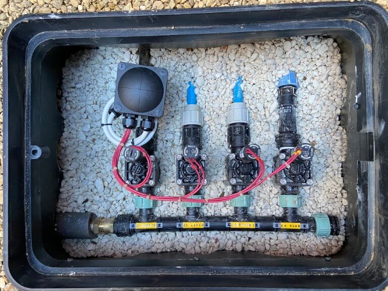
For the greatest flexibility and water consumption distribution, I decided on 4 zones, (from left to right in the valve box):
Zone 1 – Left Lawn Upper (4.82 l/m)
Zone 2 – Left Lawn Lower (8.76 l/m)
Zone 3 – Right & Centre Lawns (5.65 l/m)
Zone 4 – Line/Drip Irrigation (1.75bar pressure reducer fitted)
123456
The valve box roughly laid out to ensure ease of working on and that it left room for the pump enclosure.
Irrigation lines roughed in and trimmed, also the correct depth dug to accommodate the valve box ensuring that the lid would be at the correct height above the ground.
I used a wooden baton with pipe clips spaced at the valve outlet centers to keep the irrigation lines in the correct position without causing any strain on the valves.
After the pipe were connected to the valves and the valves to the manifold, the valve box body was notched to accept the pipes and then placed over the completed assembly, rather than work with the box in place.
Valve box all levelled and backfilled with pea gravel, decorative white stone is inside the box as I think it looks good, a 25mm conduit was ran from the controller to the valve, through this passes a 5 core 1.0mm2 cable, one core for each valve solenoid and a common return. All connections were made in an Wiska-Combi 308 IP66 rated enclosure filled with Magic-Gel after termination.
All tested and ready for closing up.
Control
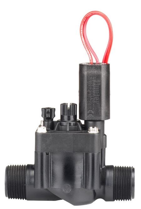
Water to each irrigation zone is via Hunter PGV solenoid operated valves, these need 24vAC to operate, applying 24v will open the valve, with no voltage present, the valve will be in the closed state.
1″ valve, Male threads, part number – HPGV1FCM ELECTRICAL SPECIFICATIONS 606800 • Minimum opening/operating voltage: 19 VAC • Maximum recommended voltage: 28 VAC • Current at 24 VAC: • 370 mA inrush, 210 mA holding, 50 Hz • Maximum operating pressure: 15.17 bar; 1517 kPa • Wire leads: 45 cm of 0.8 mm2 UL-approved wire
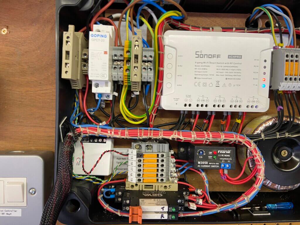
Hunter do make controllers for their range of valves but I decide to make my own using a 4 channel Sonoff Pro2 as the valve controller and a Sonoff Basic as the pump control configured as a ‘scene’.
Version 3
The Sonoff devices are paired to home WiFi and operated through the eWeLink App or dashboard, these are extremely flexible devices and ‘scenes’ can be setup, so that the actions of one device can effect the operation of another.
The channels of the 4 channel Sonoff controls the solenoid of that valve, initially I had the Sonoff set to ‘interlock’ mode, meaning that only one of the 4 channel relays can ever be ON, but once I was able to test the pumps pressure and monitor the sprinklers performance, I decided to remove the interlock enabling greater flexibility of operation.
Sonoff Scene
As this is a new system, I’m working through the best watering times, the ‘scene’ I have currently set, (a ‘scene’ is a pre configured set of events that automatically run when triggered), at 04:00 on Monday, Wednesday and Friday , valves 1 and 2 open for 40 minutes, then valves 1 and 2 close, then valve 3 opens for a further 40 minutes, valve 3 closes and valve 4 opens for a further 5 minutes.
At the end of the 5 minutes, valve 4 closes and the pump turns off.
Before going live with a scene configuration, I use a test rig to confirm operation of a scene before making it live.
The scene below is to manually operate the watering schedule and can be easily ‘tweaked’ using the eWeLink dashboard:
The scene breakdown is as follows –
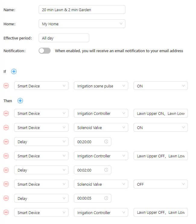
The irrigation sequence is triggered by manually operating the app.
1st action is for the Sonoff 4Ch Pro relays 1, 2 & 3 to turn ON, this in turn supplies 24vAC to OPEN the control valve solenoids to the front lawns.
2nd action is for the Sonoff Basic Smart Device to turn ON and supply power to the solenoid via a contactor, this causes water pressure to drop and the pump automatically starts.
3rd action is the Delay of 20 minutes, this is the period of time to elapse before the next action i.e. the valves are ON until the next action
4th action, at the end of the 20 minute delay time, Sonoff 4Ch Pro relays 1, 2 & 3 turn OFF and relay 4 turns ON to water the rear garden.
5th action is the 2 minute duration that water will pass through valve 3
6th action is that after the 2 minute delay time above, Sonoff Basic turns OFF and the solenoid valve closes.
7th action is a 5 second delay time before the Sonoff 4Ch Pro turns relay 4 OFF.
With all valves closed the pump will stop once a pressure of 1.5bar is reached.
I found quite early on that it was important to set up a ‘scene’ to turn OFF the Irrigation Controller relays and Pump as, in my case, access to physically operate Sonoff devices is not possible as they are within an enclosure.
A 230v/24v – (3.75A Max Output) Toroidal transformer is used to supply the operating voltage to the Hunter valves via the 4 channel Sonoff.
Version 3
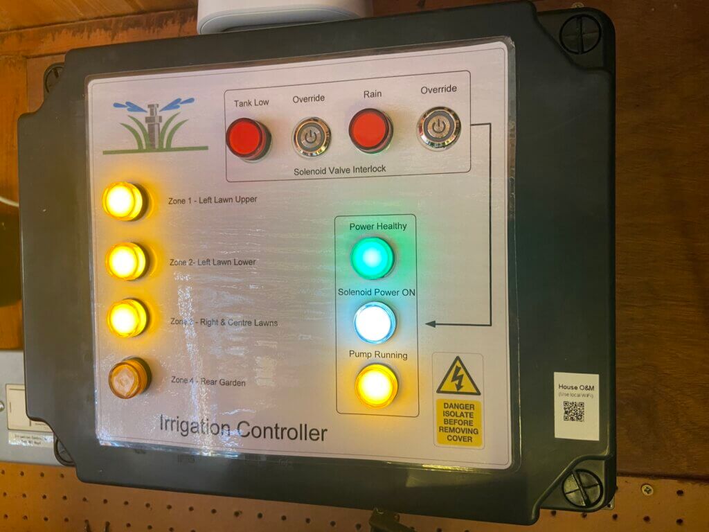
Panel shows the irrigation system cycle is running, if the feed water tank is low or if the rain sensor has activated, this will disable the solenoid contactor and the cycle will abort, operating the respective override buttons enables continued running should it be required.
Front panel label, LED lights are from AliExpress, the ‘Pump Running’ LED is switched via a AC current sensing relay with the light only being illuminated when a pre-configured load is being drawn. This gives confidence that the pump is actually consuming power and running, rather than simply powered up.
To make the panel overlay I use Visio to make the image to scale and print to A4 80gm paper, this is then covered in a self-adhesive transparent book covering affixed to the enclosure with double sided tape.
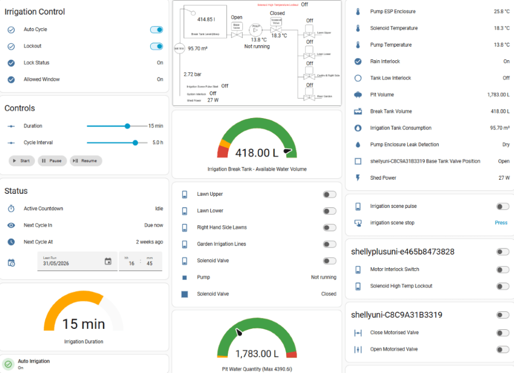
Home Assistant and Interlocks
I’m not a programmer, so I can only use what I know, this ends up a bit ‘clunky’ but it works for me.
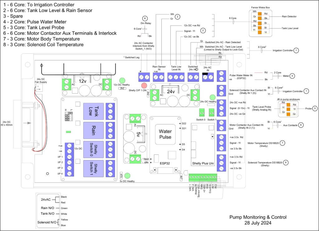
I use Home Assistant to monitor the Break-Tank water level using a submersible hydrostatic sensor from Aliexpress wired to a Shelly Uni Plus, the Shelly also has two temperature sensors attached, one for the motor casing and the other to record the solenoid coil temperature.
A recent addition has been to include a stop/start to my Sonoff watering scheduled triggered by Home Assitant, this gives me a variable watering duration and frequency.
The Shelly Uni Plus is very versatile as it also has two controllable outputs, one of these is to manually open the circuit to the motor contactor, effectively an emergency stop and the other output is linked to the solenoid temperature exceeding 500 C, if it does then the solenoid contactor circuit will open removing power from the coil.
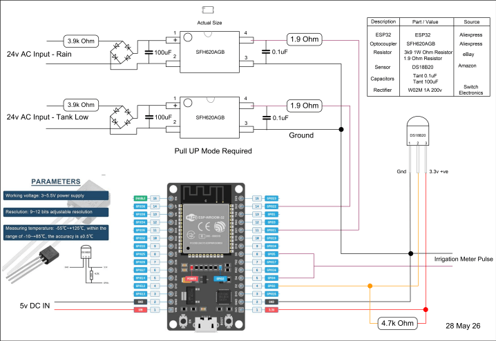
A ESP32 is used to measure the water meter pulses giving me a reading of water volume in m3 used to fill the Break-Tank, I also monitor the internal temperature of the enclosure and the status of the Break-Tank low level sensor and external rain sensor with the ESP32.
This was the most difficult part of the whole project as I did not have an understanding of the parts, only an idea of what I wanted, fortunately the cost of parts is quite inexpensive, so if I bought the wrong thing it wasn’t so much of a big deal.
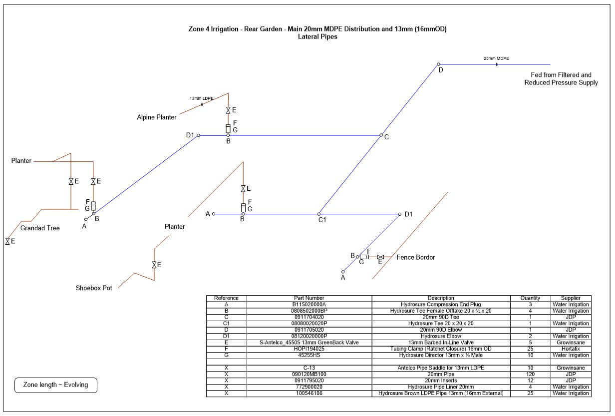
The rear garden system starts at the water control valve, the pump pressure of 4 bar is too high and must be reduced, I used a Hydrosure 1.75 bar pressure regulator connected to the 1″ control valve outlet with a 1″ BSP female to 3/4″ BSP female reducing socket, the pressure reducer has a throughput of between 0.4 – 30 lpm.
The reduced pressure irrigation water was fed to the garden via 20mm MDPE pipe, with branches made using Hydrosure compression Tee fittings with 1/2″ female offtakes.
Into the 1/2″ female offtake a Hydrosure Director 13mm x 1/2″ BSP male is screwed in, and from this 13mm LDPE pipe is connected, this is the line into which the micro irrigation parts are pushed into.
At each planter or main branch I fitted inline isolation valves, sprinkler emitters and shubblers simply push into the thin walled brown LDPE pipe, the use a key punch to make the holes is recommended.
To the left of the picture you can see one of 20 Potstream emitters connected to the main line with 6mm OD x 4mm ID micro PVC pipe.
Pipes can be buried and spray heads are very discrete.
Picture shows a Shubbler 180 emitter connected directly into the LDPE pipe, unfortunately the clematis is struggling as the dog thinks its a lamppost.
The micro irrigation emitters do not come with water usage data, I estimate that my system uses 27 litres per minute (lpm), this is just below the pressure regulators maximum throughput of 30 lpm.
Winterisation
The system will be drained during the winter months to avoid any issues with freezing, hence I was happy with the pipes buried depth and also the lack of below ground lagging.
I have adjusted the original installation to include a fence mounted bib tap so I can benefit from the pumps pressure when watering the lawn, plus the water is separately metered, so I can claim back the sewage abetment payment, the byproduct of this is a connection point to blow all the water lines out.
Although the break-tank will be empty over winter, I decided to insulate the tank when I was boxing the tank in.
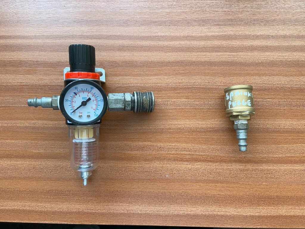
I already had a compressor (15CFM), so the parts needed to blow the system out were fairly inexpensive, these being a pressure regulator and adapter for the outside tap where the compressed air will connect to.
The regulator was £9.95 from eBay, the tap and adapter parts are listed below (Screwfix):
Bib Cock outside tap -590FA
3/4″ Female Socket – 52588
3/4″ to 1/2″ Bush – 98427
1/2″ to 1/4″ Bush – 79207
1/4″ Male Adapter Airline – 2015H
With the above, I connect the regulator, set to 2 Bar (30 psi) to the compressor with the regulated output , via an airline to the tap adapter on the outside tap, this worked really well for me.
2023, Thank you to everybody who has found this blog useful, got in touch or commented, I’ve tried to keep this blog up to date with things I’ve done to the system as you can always ‘tweak’ the system and continue to play with it, especially after the hard graft of fitting it.
Watering the lawn and tailoring it when and how long is now a simply press of a button and I would defiantly recommend investing the effort as the payback is more time for other things, year on year.
The system required very little maintenance, blowing the lines out for winter was straightforward, I did however, waste water by leaving the winterisation process a bit to late, meaning instead of using the water in the tank for the lawn, it went to drain as I didn’t want the risk of freezing damage to my tank, even though its insulated.
Bringing the system back online for a new season was very easy and non of the sprinklers malfunctioned or got stuck in the retracted position.
The main additions to my system since I initially blogged it are:
Dedicated bib tap for my garden hose fed directly off the irrigation pump, this gives me a higher pressure than the mains for washing down or using an impact sprinkler should I need to.
Tip – Know when your going to use the sprinklers for the last time, isolate the filling water to the break tank in order to leave it empty over winter.
Tip -Unplug the pump at the same time as draining down just in case it gets activated by accident and is damaged by running dry.
Tip – A number of my sprinkler body’s had moved from the vertical or sunken since installation due to the ground settling requiring the spade to come out for readjustment.
I have now hammered in a supporting pin parallel to the sprinkler and fastened with cable ties the body to the pin in a hope that this will keep things level.
Tip – One of the jobs on the lawn is to aerate and I really struggled finding the sprinkler heads without turning on the system, so I bought a pack of Survey Flags from Amazon and marked where they are and the buried pipe runs, so I know where I have to either avoid or go easy when plunging sharp tines in the ground 🙂 .
June 2026 Update
I noticed component failure in the ESP32 inputs for both rain and low tank detection, revised the design and updated the drawing, also it seems one portion of the lawn is not getting enough irrigation water, so I’ve added another sprinkler to cover this off.
After deciding on a permanent irrigation system and researching options, two brands were of serious consideration, Hunter and Rainbird, both excellent, however, it was ease of access to documentation, product range and product performance which made me decide on Hunter, specifically the rotating spray head patterns.
Where are you going to get the water from is the starting point, if you have good water pressure and flow (by measuring it), it may be possible to drive the irrigation system directly from the tap, if so you have saved a lot of money.
If you have poor water pressure, then you will need somewhere to store the water, (unless you have a well or watercourse), and a pump, as you cannot connect a pump directly to a tap.
This is the daunting bit, but it is something you can do, I used the Hunter Design Guide, which is full of useful information and the steps to follow.
I tend to overthink everything and you could throw in a few heads, linked with hose pipe connected to a tap and it might work perfectly, I on the other hand need to work everything out before I commit to effort and spending money.
Find your water pressure and flow rate.
Make a scaled drawing of the area you need to irrigate.
Look at manufactures literature and determine the appropriate head pattern and number needed to give overlapping coverage.
Total up the water consumption of the heads or the water consumption per zone if you logically can section your lawn.
Draw in pipes runs and work out pipe lengths.
Using the calculators in the FAQs or online determine pipe and pump size (if needed).
With the above info you will now know how much water you need and if you can supply that from a tap, if you can't, consider water storage and how quickly the storage tank will refill as this will be the limiting factor for how long you can water for at a given flow rate.
I've not touched on how the irrigation system will controlled as I made my own, however, these are readily available and simply send a 24v signal to a solenoid water valve to open or close at predetermining time and sequence of your choosing, some are linked to a mobile app for even more flexibility.
Pumps need to push a volume of water (output) at pressure, these are measured in Litres per minute (L/m) and Head respectively.
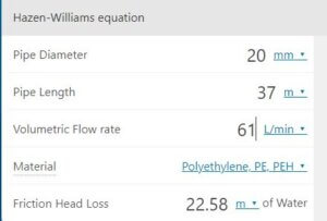
The pump used in this blog for example has an output of 61 l/min, so theoretically I can supply 19 x MP1000 360 degree rotator heads, with each using 3.18l/min at the same time, obviously this does not take into account sprinkler pipe and fittings friction losses.
Head relates to the pumps pressure and mine is 46 meters (46m), the easy way to roughly convert this to bar, (a bar is 14.7psi at sea level), is to put a decimal point in-between the number, so 46m, becomes 4.6bar.
Handy converter for Head pressure is HERE, (SG - Specific Gravity of water is 0)
Earlier I mentioned pipe friction losses, to put this in perspective my longest run is 37m of 20mm pipe and my pump pressure is 4.6bar, if I had 19 heads taking a total of 61 l/m then the pipe losses would reduce the pressure at the end of the pipe to 2.35bar, well below the pressure required for the heads to operate effectively.
Residential irrigation controller use 24vAC outputs to power water valves, whereas pumps need 230vAC.
If the controller you choose has a 24vAC output to switch a pump on, you will need a relay to switch the higher voltage and current, these are about £6 on eBay, search for AC24V Coil 8 Pin DIN Rail Electromagnetic Power Relay 10A w Base.
If the controller doesn't have a pump auxiliary output then you can use an automatic pressure switch, such as the Smart Press.
What this does is monitor the pressure from the pump, if the pressure drops, such as when the watering valves open, the pump automatically turns on and will continue to run until the watering valve/s close, also this device stops the pump if it runs out of water to protect the pump.
No, these are bought separately due to the extensive range of spray pattern types, the heads simply screw into the PRS40 body, the other bit you will need is a connection elbow to the base of the body.
From the solenoid valves to the sprinklers, I used 20mm blue poly MDPE pipe with inserts, the final connection from the poly pipe to the sprinkler body is with 1/2" flexible hose.
20mm was fine for my setup as its based on how much water it will pass in litres per minute over the total length of pipe at the correct pressure, the longer the pipe, the more pressure is dropped, hence sometimes its easier to go up to 25mm if your not sure.
This relates to how high the sprinkler 'pops up' out of the ground, either 4" or 6", the range of the water pattern is greater the higher up it is, but this is based on the design, I manage fine with a 4" lift.
The main consideration was how long was my aerators tines as I didn't want to damage the pipes at a later date, I buried mine 200mm (8") down which is the length of the trenching shovel I used.
The pipes are blown empty over winter so I have discounted any freezing risk.
Since installing my system, I did see a guy on YouTube who used a reciprocal saw to cut this trench and it worked really well as a great idea as long as you are sure you have no buried services.
The cost for my system was under £900, but I made mistakes, so this blog should save you money in unnecessary purchases, the installation was hard physical work but incredibly rewarding when finished.
The main benefit is that I can sit back and the lawn will be watered to a consistent standard, every time, allowing me to do other things, like sleep 🙂
For me it was the line irrigation to planters and drip feeders, the terminology is difficult to understand so I ended up buying lots of things which are now sat in a box, fortunately the bits are relatively inexpensive.
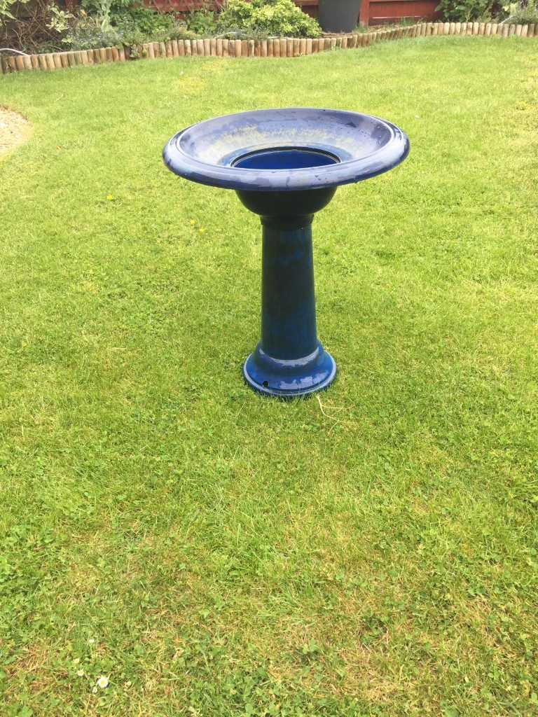
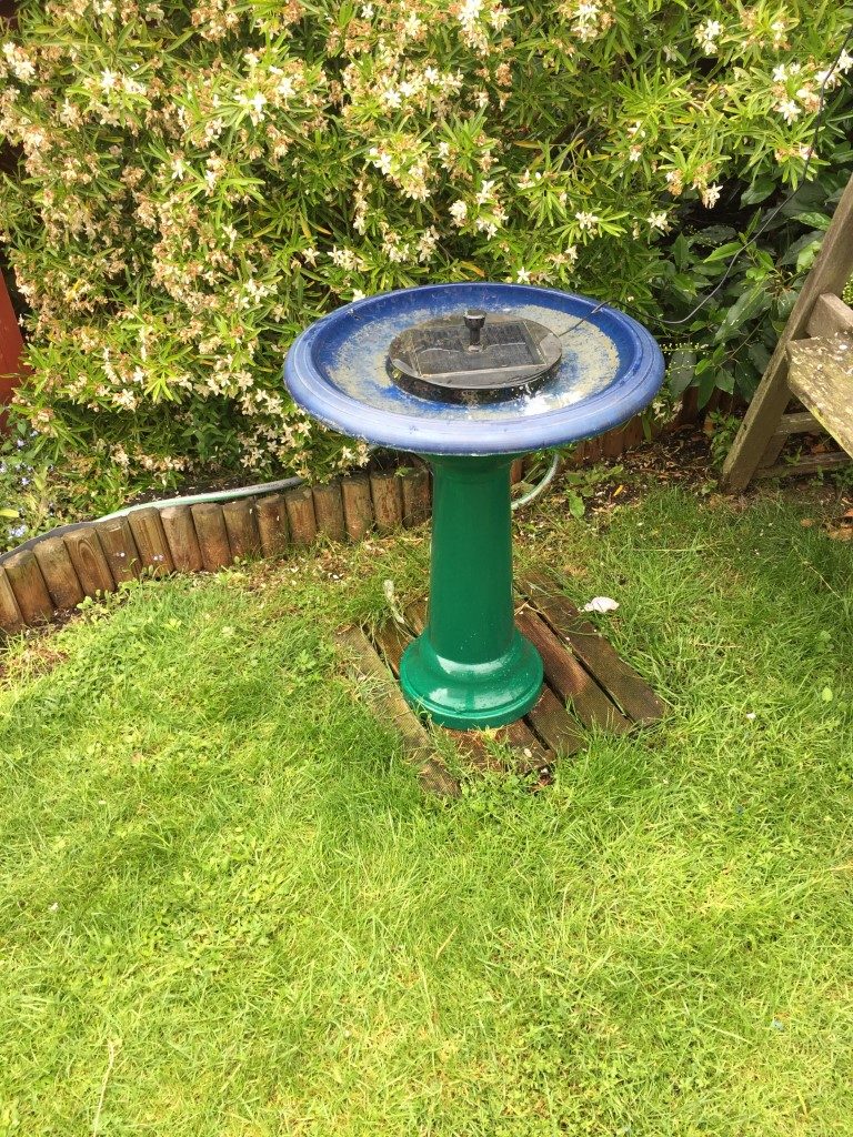
I bought my bird bath second hand for £10 and have had it for several years, I’ve always hated the colour and topping it up with the watering can every day was getting to be a pain.
So I thought I would ‘ kill two birds with one stone’, (I know, not the best phase considering the context), anyway, a nice little project in the making.
My original design ended up way to complex, the plan was to use a Programmable Logic Controller to drain the bowl and refill it everyday, plus some other tweaks such as overfilling the bath to flush out waste and only draining down at night etc.
I did a relality check and simplified the design to simply fill when the level in the bowl gets low, however, the plumbing manifold was made to allow auto draining if I choose to do it later.
CurrentOperation – This is very simple and needs no manual intervention. With the water supply and power on, the liquid level controller keeps the solenoid fill valve closed as long as a circuit is made via the water from the common connector (metal tank connector) to the low level brass stud.
When the water level drops below the low level stud and the contact to the common connector is missing, the controller, after a short delay, powers the fill solenoid valve and water enters the bird bath, once the water touches the upper contact (high level), the solenoid power is removed and the valve closes.
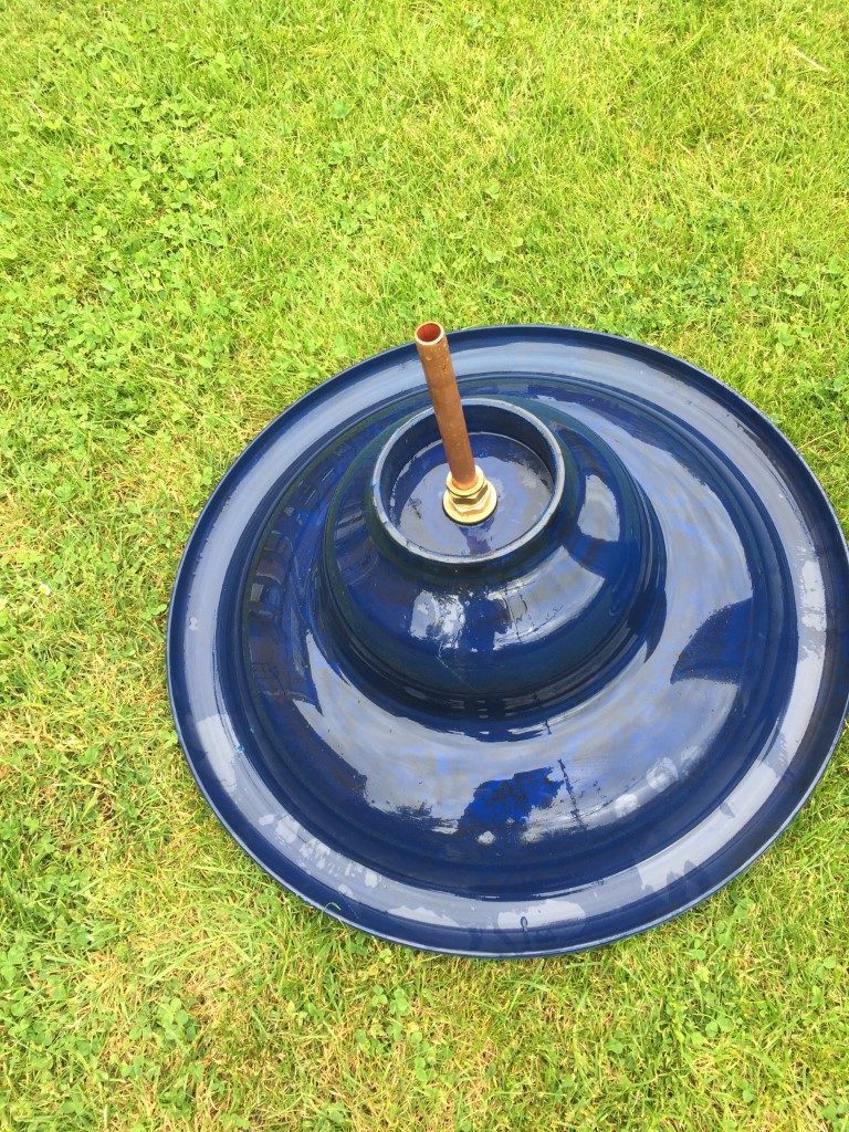
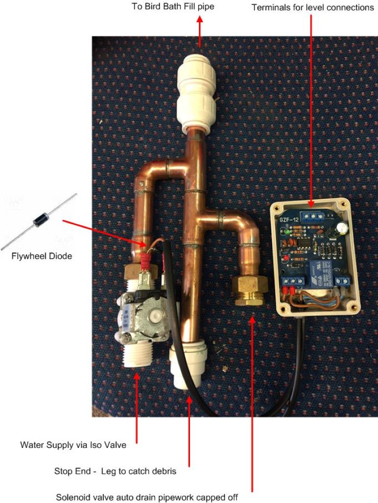
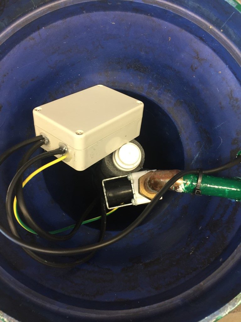
How it was made – As the bird bath is made of plastic and the top bowl lifts off the column, I was able to put hardware out of view inside the base.
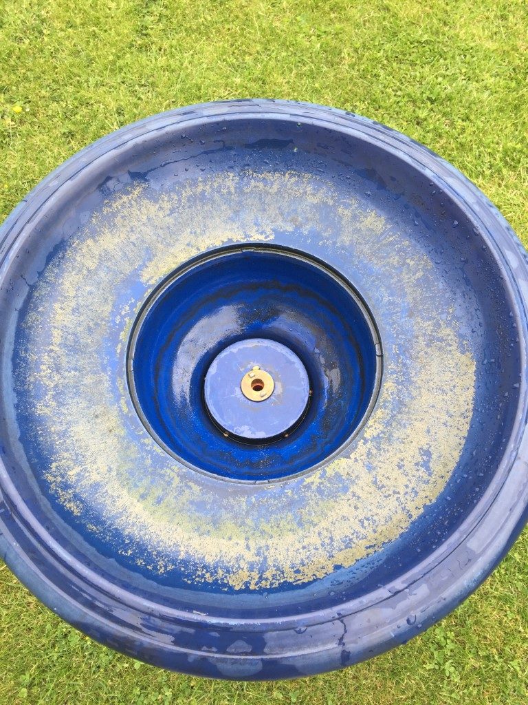
First job was to drill and fit the 15mm Tank Connector (£2.79) and a small length of 15mm copper pipe in the top bowl, this will connect to the filling manifold via a push fit coupling, the copper stub will also act as a ‘Common’ connector for the level sensor circuit.
The manifold is made of 15mm copper pipe with end fed fittings, the manifold is connected via a 15mm ‘push fit’ connection to the bowl stub, thiis makes maintenance very easy as it all comes apart quickly. The finished pipework is fully lagged.
The liquid level control PCB was off eBay (£3.65 and) fitted neatly inside an IP rated enclosure I already had, in the picture above you can see an earth wire which is soldered to the stub pipe from the bowl and the black cable is a two core to the high and low level stud contacts.
The solenoid is 1/2″ version, 12vDC and connects to the water supply via 15mm tap connectors with fibre washers (£1.50 @ B&Q), I fitted a flywheel diode across the terminals to avoid pitting the PCB relay contacts, the valve was off eBay and cost £4.32.
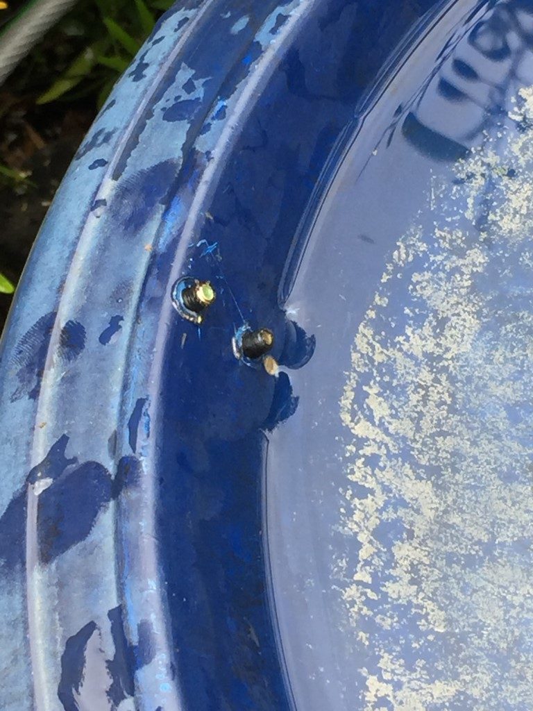
The studs are Pan Head 12mm x 4mm brass machine screws commonly used for metal conduit box lids, the studs are positioned at the low level and high level marks. On the underside I have used hot melt glue to secure the sensor connecting wire.
Finished project and a new colour, Winsor Green. The water supply to the bird bath is via a hose from an outside tap, the connection at the bird bath is via a hozelok connector with an isolating ball valve, the valve is ‘gagged in’ so the when the solenoid opens, the bath fill is quite slow,
12vDC to power the circuit board and solenoid is fed from an external IP rated socket with a small plug in PSU.
A blog about stuff that interests me or I have done.
We use cookies on our website to give you the most relevant experience by remembering your preferences and repeat visits. By clicking “Accept All”, you consent to the use of ALL the cookies. However, you may visit "Cookie Settings" to provide a controlled consent.
This website uses cookies to improve your experience while you navigate through the website. Out of these, the cookies that are categorized as necessary are stored on your browser as they are essential for the working of basic functionalities of the website. We also use third-party cookies that help us analyze and understand how you use this website. These cookies will be stored in your browser only with your consent. You also have the option to opt-out of these cookies. But opting out of some of these cookies may affect your browsing experience.
Necessary cookies are absolutely essential for the website to function properly. These cookies ensure basic functionalities and security features of the website, anonymously.
Cookie
Duration
Description
_GRECAPTCHA
5 months 27 days
This cookie is set by the Google recaptcha service to identify bots to protect the website against malicious spam attacks.
cookielawinfo-checkbox-advertisement
1 year
Set by the GDPR Cookie Consent plugin, this cookie is used to record the user consent for the cookies in the "Advertisement" category .
cookielawinfo-checkbox-analytics
11 months
This cookie is set by GDPR Cookie Consent plugin. The cookie is used to store the user consent for the cookies in the category "Analytics".
cookielawinfo-checkbox-functional
11 months
The cookie is set by GDPR cookie consent to record the user consent for the cookies in the category "Functional".
cookielawinfo-checkbox-necessary
11 months
This cookie is set by GDPR Cookie Consent plugin. The cookies is used to store the user consent for the cookies in the category "Necessary".
cookielawinfo-checkbox-others
11 months
This cookie is set by GDPR Cookie Consent plugin. The cookie is used to store the user consent for the cookies in the category "Other.
cookielawinfo-checkbox-performance
11 months
This cookie is set by GDPR Cookie Consent plugin. The cookie is used to store the user consent for the cookies in the category "Performance".
CookieLawInfoConsent
1 year
Records the default button state of the corresponding category & the status of CCPA. It works only in coordination with the primary cookie.
PHPSESSID
session
This cookie is native to PHP applications. The cookie is used to store and identify a users' unique session ID for the purpose of managing user session on the website. The cookie is a session cookies and is deleted when all the browser windows are closed.
viewed_cookie_policy
11 months
The cookie is set by the GDPR Cookie Consent plugin and is used to store whether or not user has consented to the use of cookies. It does not store any personal data.
Functional cookies help to perform certain functionalities like sharing the content of the website on social media platforms, collect feedbacks, and other third-party features.
Performance cookies are used to understand and analyze the key performance indexes of the website which helps in delivering a better user experience for the visitors.
Analytical cookies are used to understand how visitors interact with the website. These cookies help provide information on metrics the number of visitors, bounce rate, traffic source, etc.
Cookie
Duration
Description
_ga
2 years
The _ga cookie, installed by Google Analytics, calculates visitor, session and campaign data and also keeps track of site usage for the site's analytics report. The cookie stores information anonymously and assigns a randomly generated number to recognize unique visitors.
_ga_92TJCVGJP2
2 years
This cookie is installed by Google Analytics.
_gat_gtag_UA_48800884_1
1 minute
Set by Google to distinguish users.
_gid
1 day
Installed by Google Analytics, _gid cookie stores information on how visitors use a website, while also creating an analytics report of the website's performance. Some of the data that are collected include the number of visitors, their source, and the pages they visit anonymously.
CONSENT
2 years
YouTube sets this cookie via embedded youtube-videos and registers anonymous statistical data.
is_unique
5 years
StatCounter sets this cookie to determine whether a user is a first-time or a returning visitor and to estimate the accumulated unique visits per site.
is_visitor_unique
2 years
StatCounter sets this cookie to determine whether a user is a first-time or a returning visitor.
sc_is_visitor_unique
2 years
StatCounter sets this cookie to determine whether a user is a first-time or a returning visitor.
Advertisement cookies are used to provide visitors with relevant ads and marketing campaigns. These cookies track visitors across websites and collect information to provide customized ads.
Cookie
Duration
Description
NID
6 months
NID cookie, set by Google, is used for advertising purposes; to limit the number of times the user sees an ad, to mute unwanted ads, and to measure the effectiveness of ads.
VISITOR_INFO1_LIVE
past
A cookie set by YouTube to measure bandwidth that determines whether the user gets the new or old player interface.
YSC
session
YSC cookie is set by Youtube and is used to track the views of embedded videos on Youtube pages.
yt-remote-connected-devices
never
YouTube sets this cookie to store the video preferences of the user using embedded YouTube video.
yt-remote-device-id
never
YouTube sets this cookie to store the video preferences of the user using embedded YouTube video.
yt.innertube::nextId
never
This cookie, set by YouTube, registers a unique ID to store data on what videos from YouTube the user has seen.
yt.innertube::requests
never
This cookie, set by YouTube, registers a unique ID to store data on what videos from YouTube the user has seen.


