I have a number of BRK Smoke and Heat detectors which are interlinked to all sound on activation of any detector, I needed a way of linking the detectors to my house alarm which in turn would alert me on the mobile app.
A quick Google search flags a BRK RM4 relay interface which is triggered by the interconnect wire, the problem is they are only for the US market and work at 120v AC, this was confirmed with a phone call to the UK BRK representative.
I decided to take a punt and bought a RM4 from a US vendor, this took ages as a large number of seller just wouldn’t entertain shipping to the UK.
The moment the RM4 arrived, it was cut open 🙂
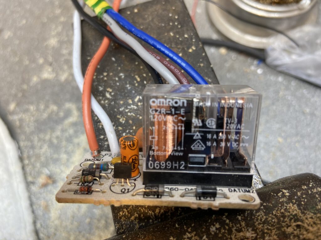
After checking the component data sheets the only parts which needed upgrading were the 2.2uF capacitor from 50v to 250v and the relay from 120v AC to 240v AC (part 369-337: G2R-2 230v).
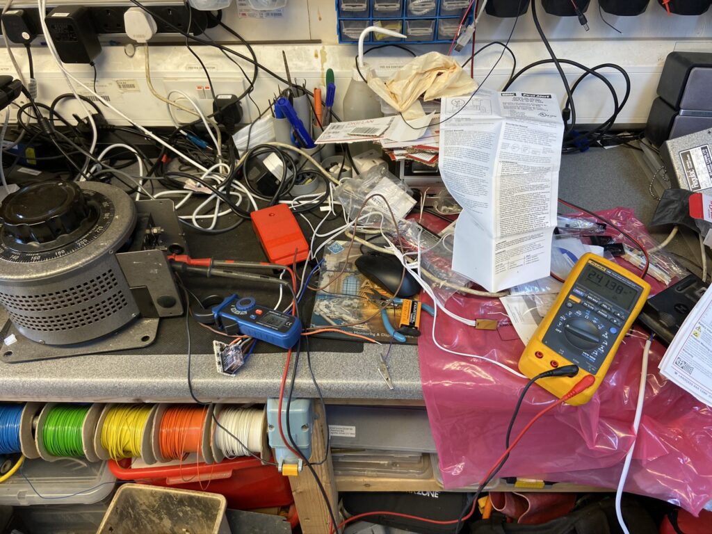
Before swapping the parts I set up a ‘rough and ready’ test rig using a variostat to provide 110v AC to the RM4, a clamp meter was used to measure RM4 consumption and a 9v battery ready to place a voltage on the interconnect wire simulating an alarm condition, this worked fine.
After exchanging the capacitor and relay the RM4 was back on the rig and the supply voltage gradually increased to 240v AC while keeping a close eye on the current consumption which slightly increased from 2.8mA to 3.3mA.
The interface works as expected and the relay energises when a voltage is on the interconnect wire, it must be noted that the interface requires a supply voltage for it to work, the relay will not work in a power outage.
Sorry, bit of a messy picture, the RM4 is powered via the Rheostat with a ‘clamp on’ ammeter monitoring current draw and multimeter displaying the input voltage to the RM4, the PP3 9v battery was to simulate an trigger on the ‘Interconnect’ signal wire.
The RM4 wires are coloured for the US market and required sleeving with UK colours:
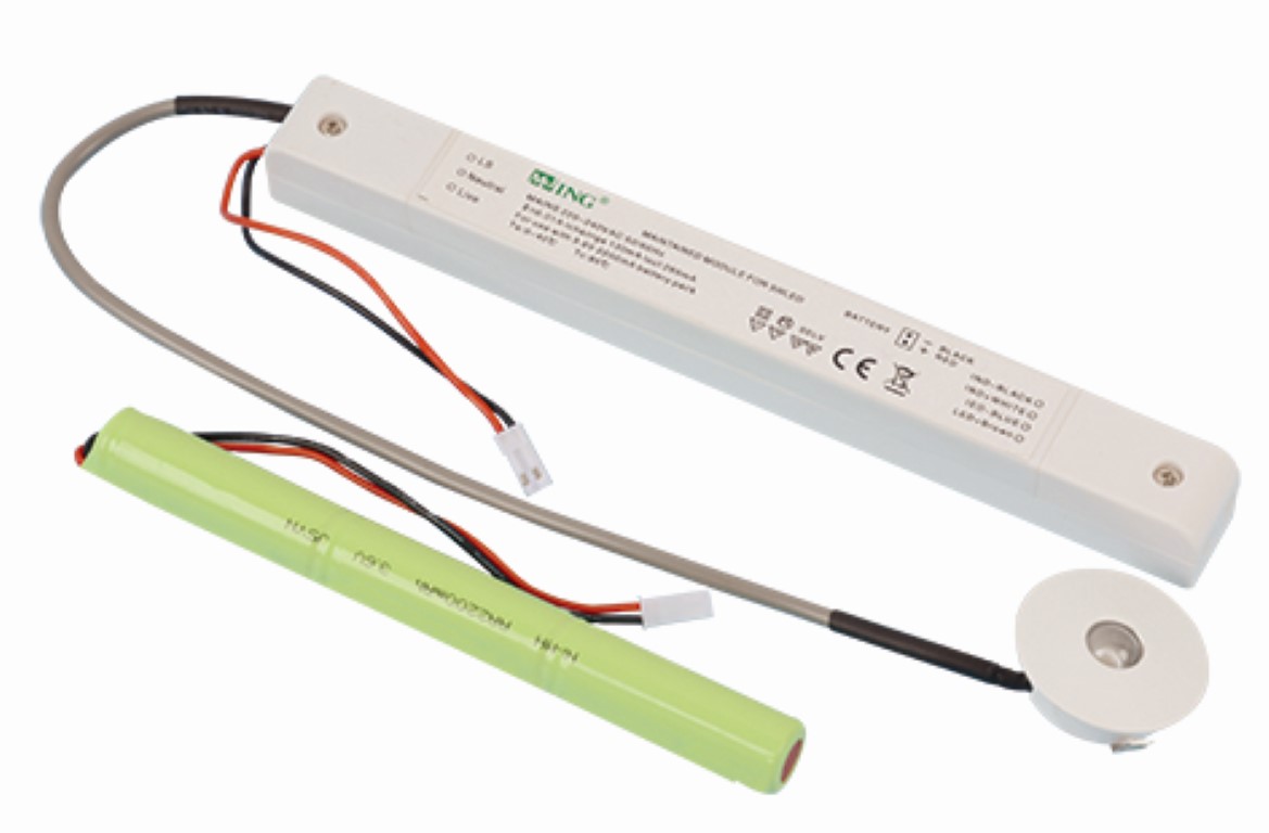
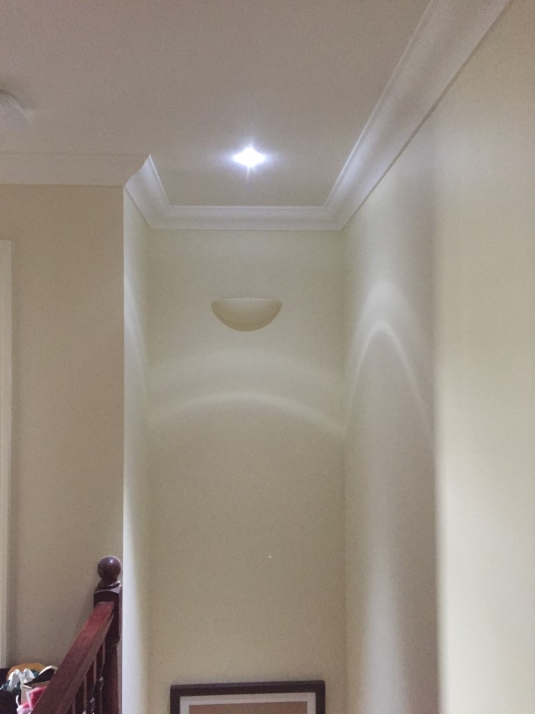
I saw a very similar discrete emergency light fitting recently and thought that would be a good idea over the stairs at home, looking on eBay I saw the above unit (MJ-LED-DZ09 by Zenergy) for £14.95 and bought one.
Prior to use, the instructions recommend charging the battery for no less than 24 hours before use as it comes discharged, this I did.
The LED light housing is really neat, it requires a 32mm hole (1 1/4″) drilling to accept the light body which is held in the hole by spring clips on either side, the electronics are in a low profile enclosure and this will easily pass through the 32mm hole.
Installation was very simple, I marked the center of the ceiling over the stairs, using a 32mm hole saw, checking that their wasn’t any joists or obstructions in the loft above the ceiling before drilling.
To stop plasterboard dust going everywhere whilst drilling the hole, I used a plastic fast food container as a ‘dust catcher’.
To make this, I cut a hole in the container so that the hole saw shaft passed through the container into the chuck, this allowed me to hold the container steady whilst drilling the hole at slow speed so that all the dust was trapped in the container.
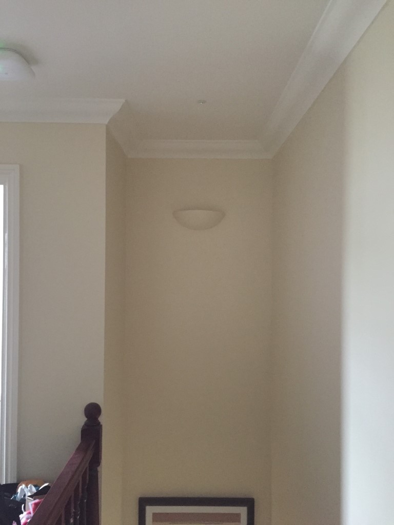
After pushing the electronics enclosure through the hole, I used decorators caulk around the inside lip of the LED light, before pushing the light into the hole, the reason for the caulk was to form a decent seal to stop any draft marks appearing around the fitting at a later date.
In the loft, I connected the emergency light 230v power to the upstairs lighting circuit (after isolating the supply!), when the power was turned on, the battery was then plugged into the unit ready for testing.
With the power on, a tiny green healthy LED is lit, when the power is off, the green LED goes out straight away, and within 2 seconds, the main white escape LED lights, I assume the delay is to avoid and short duration blips bringing on the main LED.
The light from the unit is very bright and cool white is colour.
Quick Details from Web Site
LED – 1 X 3W LED
Material- Poly Carbonate for conversion body & aluminum LED body
Mounted – ceiling mounted
Life time of battery – 4 years
Light Output – (Emergency) 170lm
Lamp protection – over charge and discharge protection
LED indicator – Green indicator
Charging current – 90mA
Convert voltage- 155V AC
Discharging current – 500mA
Discharge duration – 3 Hours
Spec of battery- 3.6V 2200mAh NI-MH Batery
Packing – 38.5 x 35x 32.5cm 50pc/ctn
IP Rating- IP20
NO.:MJ-LED-DZ09
Application:
The series use for emergency lighting. The unit will provide 3W maximum output power at emergency mode.They are designed to be highly efficient and highly reliable, and with short-circuit protection; overcharge protection;over discharge protection and over temperature protection.
Important information for the installion:
The unit uses dangerous mains voltage,(220-240Vac, the converter will be with the emergency mode when the mains voltage is less than 65% of rated voltage) it should be installed by a qualified electricians only according to European safety standard or relevant nation regulations.
Connect the LED spotlight to the emergency LED converter with correct polarity according to the schematic drawing.
Connect the unit to AC power only after the wiring completed between emergency converter, battery and spotlight.
If the emergency converter is used for purposes other than originally intended or it is connected in the wrong way, no liability can be taken over for possible damages.
Specifications:
Model
Main power supply
Main power cut off
MJ-LED-DZ09
LED Spotlight off, green indicator on
LED spotlight on, green indicator off
I’m really impressed with the product, and its another safety related home improvement which we hope is never needed in anger.
Update 6 June 18
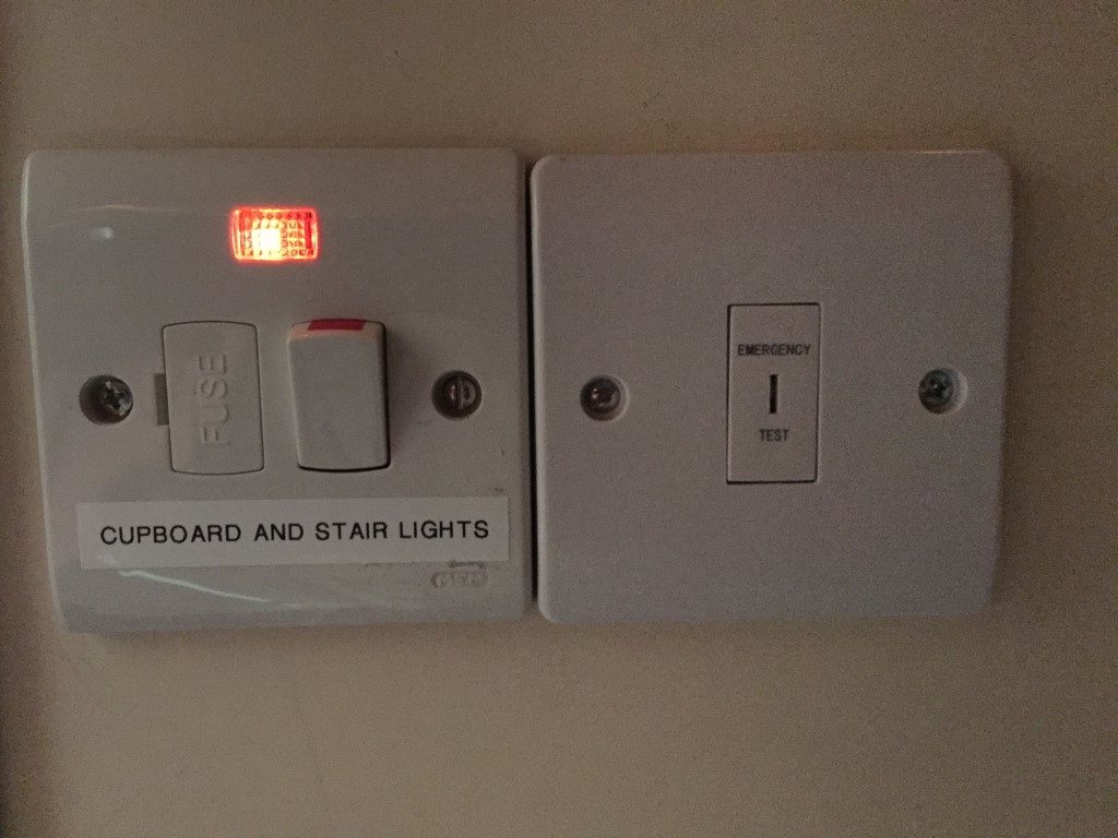
Installed a Emergency light test switch rather than turning the lighting power off, these are just under £3.00 and include the ‘fish tail’ key.
The switched fused connection unit is for a cupboard light and Hive light fitting which are fed with 0.75mm cable, the emergency lighting is fed with 1.5mm cable and is not fed from the fused side of the fused connection unit.
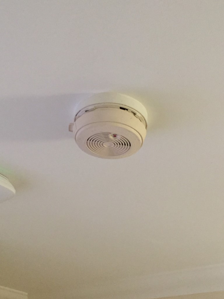
I have two BRK 86RAC Ionisation type smoke detector, one in the Hall and the other on the upstairs Landing, these were installed by the builder and in 2008 I added a heat detector (690MBX) in the garage, all three devices are mains powered with battery backup and are interlinked so that they all alert to a detection.
BRK 86RAC Discontinued ionisation smoke detector.
Checking the batteries in the smoke detector I noticed the unit has a life of 10 years from date of manufacture which was 21 June 2002, as the date of noticing this was 4 March 2018, they are well overdue for replacement!
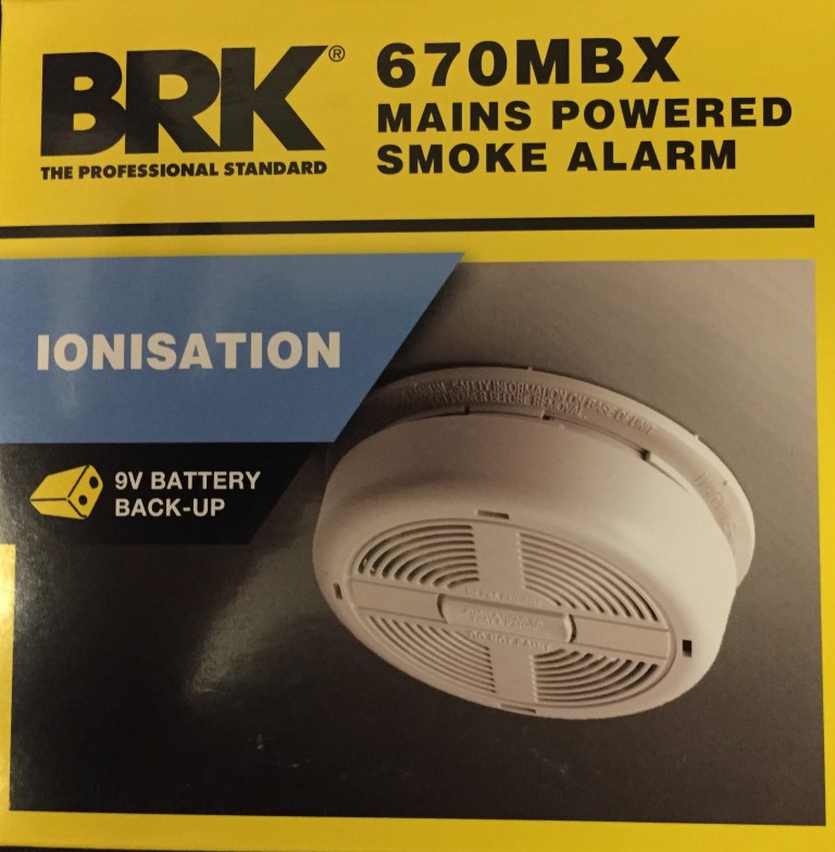
The BRK 86RAC is no longer produced and has been replaced by the BRK 670MBX.
Checking my local Screwfix had BRK ionisation smoke dectors (part number 81969) for £12.99 and the surface mounting kit (part number 30152) for £2.99, I thought I would add two more to my system, so bought four of everything.
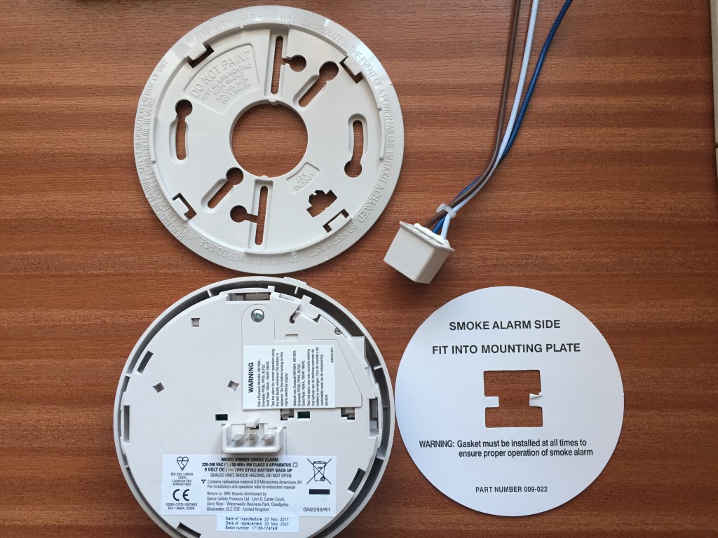
On opening the boxes, I didn’t realise that the detectors came with 9v PP3 type batteries, so wasted £6.00 buying them, and the other thing was that they are not a direct replacement, the 86RAC base is a smaller size and the plugin connector is a different style.
In the box are the above plus instructions, sticker for the consumer unit and protective detector cover, no fixing screws are supplied.
Fitting –
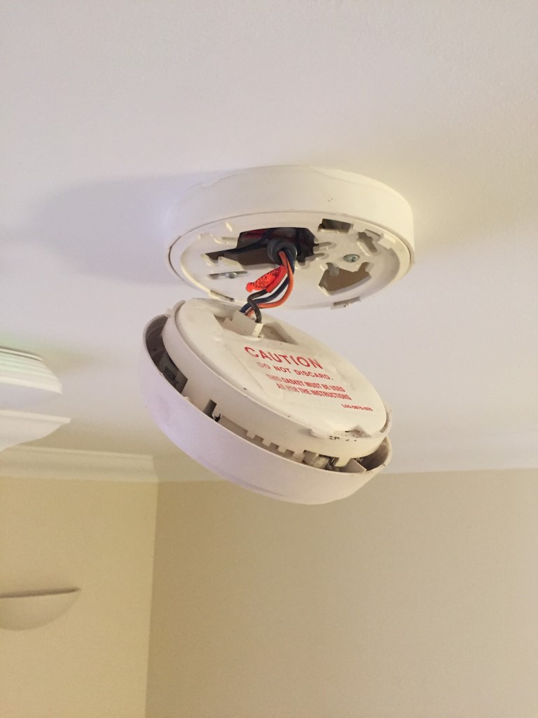
First job was to isolate the mains supply to the existing detectors which are on their own dedicated circuit, once this was done I twisted the detectors from the base to allow me to take photographs of the wiring.
The existing wiring was Black to Neutral, Brown to Live and Orange striped is the interconnect wire, 670MBX uses Blue for Neutral, Brown to Live and Grey for the interlink, the existing detector had a ferrite bobbin through which all the detector wires passed, whereas the new model doesn’t, I decided to reuse these on the replacement units.
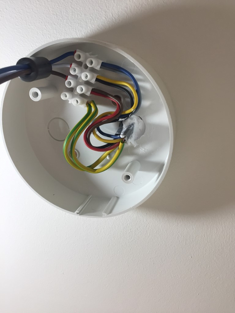
Once the cable colours were recorded, the detector was unpluged and the base completely disconnected to allow the replacement of the new base, once this was screwed into place, the connections were remade.
The wiring in the base looks more complicated than it should due to the change of cable colours, the existing 1mm CSA 3 core and earth used the pre EU harmonisation wire colour convention of Red, Yellow and Blue, the cable to the new additional detectors which I have installed are in the office and IT cupboard, uses harmonised colours of Brown, Black and Grey, as the installation has mixed wire colouring, a warning notice to this effect is fixed to the consumer unit.
While the new detector was on the desk, the battery was dated and connected, without a battery installed the detector will not engage in the base, this is a safety feature.
After making the connections, the detector base was fixed to the surface fitting by two supplied screws, the cardboard sealing gasket was then pressed into place covering the detector base fixing holes, the next step was to plug the lead into the base of the detector and lastly twist the detector into the base.
Within the baseplate of the detector is a small plastic extrusion which can be removed, this is used once the detector is installed as a locking clip preventing the detector being removed from the base with the clip in place.
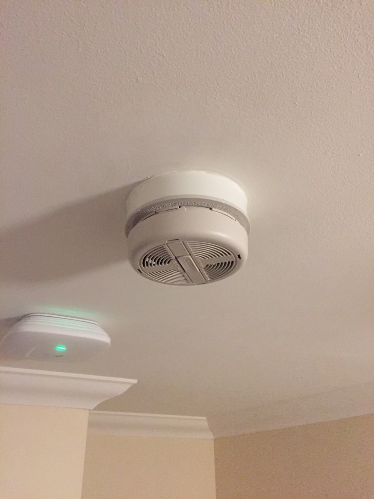
With all detectors connected and new ones installed, mains power was turned back on, and each detector was then checked that it showed a continuous green LED for power healthy and a flashing red LED every 60 seconds to show the detector is functioning.
The center test button on each detector was pressed and held, this caused the local unit to sound, followed a moment later by all the other interconnected heads.
I had already sealed the cables passing through the ceiling, the final job was to seal the base to the ceiling and paint the exposed part of the ceiling as a result of the base being smaller than the original one.
A point to note was that I was going to use flushed in circular dry lining boxes to make the connections in and hold the base, this would have made the smoke detector sit closer to the ceiling but would of meant a large hole being made, so I decided against it.
Job was very straightforward, adding new detectors was easy as I looped off the landing detector to the other units which were only a few meters away.
I’ve wanted to do a few tweaks to the home workshop for a while, and today I finally got round to it.
The easiest job was done first, this was to install an additional light fixture to house a Hive Smart Light, this has been added to the global Group ‘Lights’ in the Hive App, by the simple Alexa command ‘Lights On’ or Lights Off, all Hive lights and sockets with connected lights operate, this is really handy feature should we hear any noises in the night.
The light can also be turned on independatly via the Hive App or via interfaces to other Apps’ or IFTTT.
I bought a cheap and cheerful circular light fitting for the Hive light as it’s very easy to wipe clean. In the application I was using the hive light for, the lamp required an unswitched mains supply.
The besa box Tee above the Exocutor had the ‘loop in, loop out’ wiring for the suspended light, the new fixture was simply fed from permanent live from this and was up and running within 5 minutes.
The second job is something that I have wanted to for ages but the cost of the technology was prohibitive, until now!
The picture above shows my conversion of a garage into a workshop, this was done in 2007, after the walls were lined, the dado trunking and socket outlets were installed, you can make out that I have used Red and White sockets, the Red ones are not switched via a contactor, whereas the white ones are.
Operating any of the three ‘Emergency Off’ latching buttons, will disconnect the sockets and non Red fused connection units. A Red LED indicator by the bench illuminates when the Power to the sockets is ON.
The existing arrangement works fine , but I have always wanted an easy remote ‘power off’ ability, as I have had to check on countless occasions if I have left a soldering iron ON, my usual ‘gotcha’ is the compressor ‘kicking in’, in the middle of the night.
With the cost of internet enabled and Alexa compatable WiFi Smart switches coming down to a ridiculous price of £4.39, now was the time to make the addition of remote operation.
To the left of the change-over switch is the consumer unit feeding the Garage sockets via a 20A MCB, a 3A MCB is for the contactors control circuit via the latching stop buttons.
Cables fished in, Left side is the supply to the Sonoff, the Right side is the Sonoff’s switched output.
Sonoff connected and cables dressed in to consumer unit.
Completed job with Sonoff showing link to server established, before starting the work I configured the Sonoff in the house and enabled the power to be ON by default, once this was done I checked that it work in the Garage.
The configuration is very easy and the App is EWelink, also this is linked to Alexa, the image below is a screen shot of the EWelink App.
Update – 5 Jan 18, E-WeLink servers have failed this means that control of the Sonoff devices is not possible, no time given as to restoration of service 🙁
14 Jan 18 – Service back up and running and all Sonoff devices now working.
This blog is from 2014 updated in Feb 2018 and refreshed in July 2022.
A few years ago just before Christmas we had an extended power outage, not only didn’t the telly work :-(, but all the food in the fridge/freezer was nearly spoiled which would have been a disaster, it was at that point I decided to install an external power inlet point for a petrol generator and some form of switching.
I decided early on that I only needed the essentials to be on the generator backup, this included the heating, lighting, kitchen power circuit and cooking, it was important that I confirmed which circuit breaker control which circuit, this is important as I need to isolate high current consuming circuits so as not to overload the generator when online.
The generator I bought was a Honda 3kVA manual pull start unit off eBay (it later transpired that it wasn’t a genuine Honda, you’ve got to love shysters), which should be plenty big enough, if we need to heat water for hot drinks we’ll use the gas hob kettle rather than the electric one so as not to overload the genny, I can keep an eye on actual consumption due to a digital power monitor which is incorporated into the transfer switch enclosure.
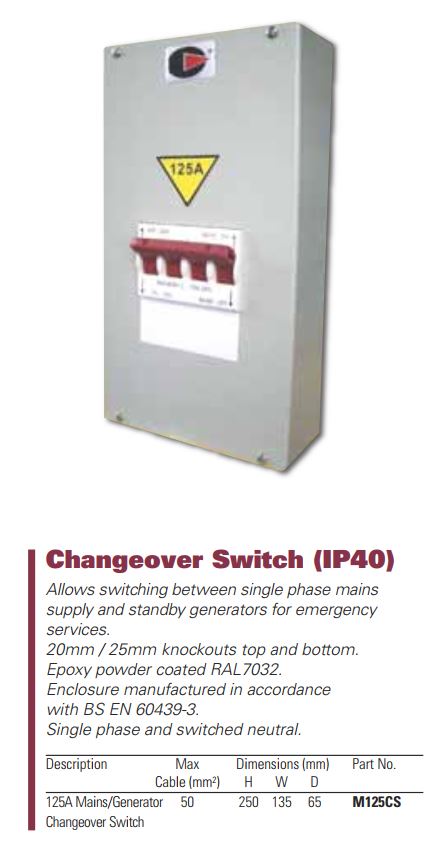
As the generator is a manual pull start their was no point having an automatic power transfer switch, so I built a manual one.
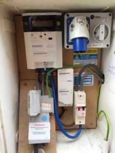
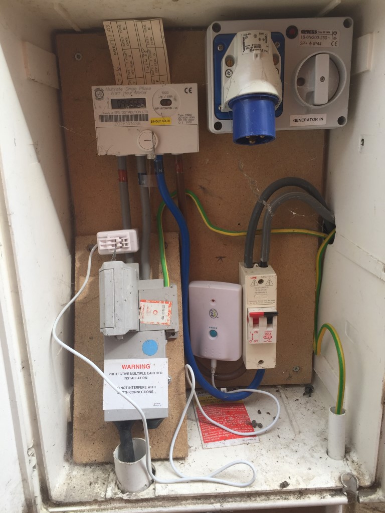
So, outside in the meter cupboard is a 16A switched male socket inlet, this has been modified with a power indicator which illuminates when the generator is running, the generator plugs into this external outlet via small lead, two things to note, first that the petrol generator is outside so that fumes can’t get into the house and secondly that the power lead from the generator to the house uses a female socket to ensure that no exposed pins can be touched with the generator running, removing any shock risk.
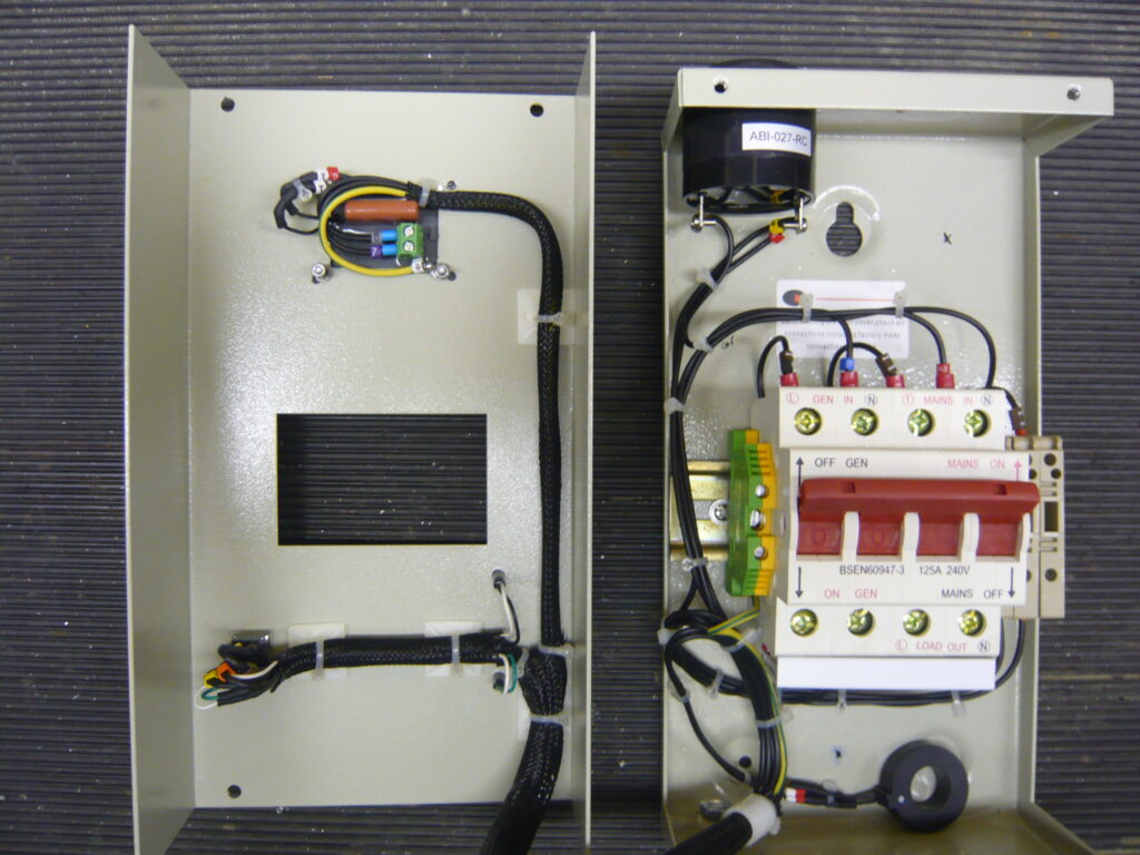
From the external socket a 4mm cable feeds into one side of a power transfer switch, this switch has a capacity of 125 amps and is a break before make type, this will ensure that it is not possible to back feed power to the generator from the utility supply during the manual switching operation.
The supply from the utility company also go to this transfer switch, the output of the switch goes to the consumer unit and from here to each of the circuits in the house.
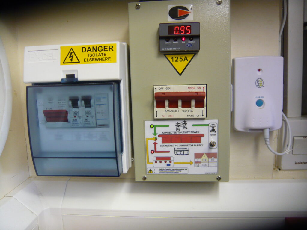
Operation – under normal conditions, the transfer switch is set to Utility supply, this is confirmed by a green 230vAC LED wired directly across the supply via a1A fuse.
On a sustained power outage, the generator is hooked up and started, the switch on the external socket inlet is turned to ON and the Red generator power available LED is lit, (the 230vAC LED is wired directly across the generator supply at the switch via 1A fuse).
Non essential circuit breakers in the consumer unit are turned to the OFF position, once done, the transfer switch generator power available LED is checked, and if still available, the transfer switch is operated to import power to the consumer unit from the generator.
As the transfer switch is in the garage, I would not know if the Utility power had been restored, I therefore fitted a 230vAC buzzer across the Utility supply via a switch, restoration of utility supply is indicated by an audible tone which obviously is switched OFF in normal Utility power operation.
To check that the generator is not being electrically overloaded, an ACM20 panel meter was fitted, this displays, amongst other things is power (Watts) being drawn, which is very useful for this monitoring function.
Original electricity cupboard
Supply company lowered the isolator to make room for the generator intake switch.
Transfer switch mounted next to garage dado power consumer unit.
Transfer switch fully installed with both Utility and Generator power available.
Consumer modified to RCBO and remote power off to garage supply
Smart meter installed August 2017
Generator plugged in on test.
System on test, instruction by the consumer unit, give the start-up and shutdown process including which breakers to turn off before changing over, the transfer switch panel meter is used for monitoring load to make sure the generator is not overloaded.
Update
17th December 2022 – I’ve noticed over a few months that the ACM20 display has been acting weird, and today it finally gave up giving me believable readings, so a new one is on order from Mouser.co.uk for the sum of £80.47.
31 January 2023 – Taken a while but finally got round to replacing the original meter, the details of the new one are:
www.murata-ps.com
ACM20-4-AC1-R-F-C
Part Number – 4900204
The only issue I had was getting the Current Transformer wires the right way round as I had to extend them, you know if its wrong when the Wattage stays at zero!
I have been after getting a Smart Meter installed for the past few years so I could monitor my energy usage in near real time, my original supplier (EON) said that as my gas was supplied via IGT infrastructure, they could not install Smart Metering, speaking to British Gas (BG) and my IGT they said this wasn’t a problem, so I switched supplier.
Surprise, surprise, when I came to register for a Smart Meter to be installed British Gas, they said it was not possible for the same reason that EON gave.
I took the case to OFGEM, but my case was undermined as the telephone conversation recording with the BG operative and myself could not be found, however, due to an extensive e-mail trail, OFGEM ruled that BG were to give me a written apology.
Winding forward to the 24 August 2017, I upgraded my British Gas mobile app and ‘Book a Smart Meter’ button appeared, with a wry smile I pressed the button and hey presto it accepted my booking, whereas previously this has been declined, and an appointment was set for 3 August 2017 between 13:00 and 17:00.
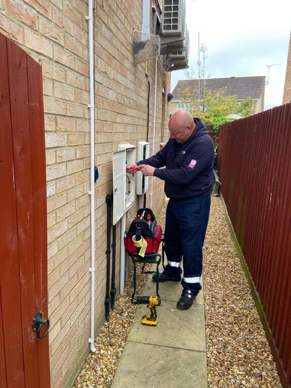
The BG guy rang before he arrived, he introduced himself as Ashley and was really friendly, taking him to the external meter cupboards I had my fingers crossed that nothing would get in the way to causing a cancellation, as it was, no problems were presented so the installation of gas and electricity smart meters could go ahead.
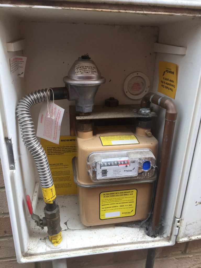
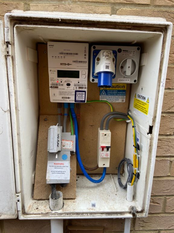
The picture above shows my old meter with an OWL energy monitor transmitter with a clamp on Current Transformer attached to the incoming phase wire, Ashley started on the electricity meter swap out first after checking the nearest socket with a plug in tester for confirmation of correct polarity and earth continuity, he turned off the consumer units main isolator and central heating boiler before pulling the main service fuse.
Due to the larger size of the smart meter, he had to shorten the tails from the cut-out, apart from that, the exchange took about 40 minutes in total and the OWL monitor is now redundant!
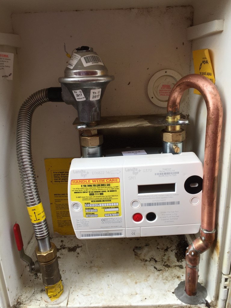
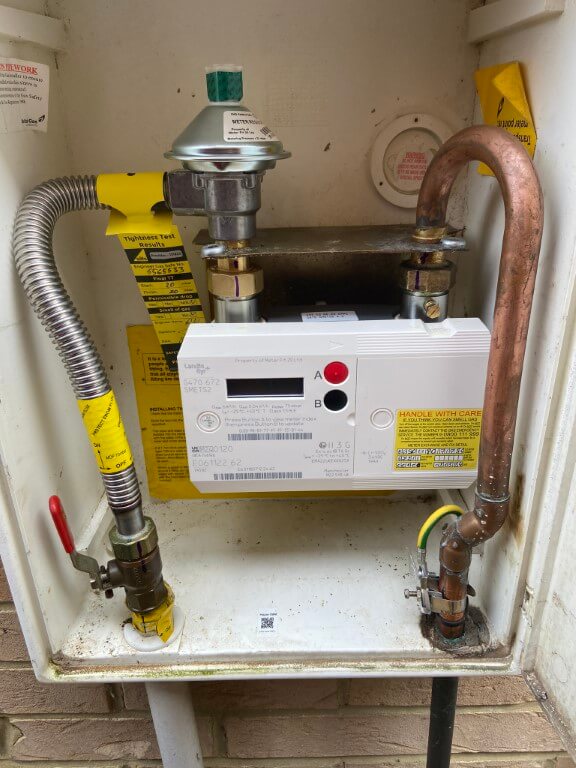
The replacement of the gas smart meter was a bit more challenging as the new meter would not fit without meter exit pipework modifications.
Ashley isolated the gas supply and stripped out the old meter, regulator and anaconda pipe, replacing the regulator and pipe with new, he offered the meter up and noted where the meter outlet pipe needed modifying.
He cut out the existing pipe and soldered in a prefabricated swept connector and it was a perfect fit.
Link to Landis & Gyr Gas Meter Information
He tightened all connectors after replacing all ‘O’ rings with new ones and gave his works a pressure and leak test, once finished he sealed the outlet hole from the meter cupboard with flue cement.
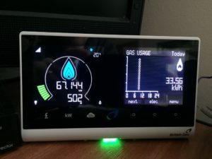
He then ran through the display and went on his way, overall it took about 2 hours to fit the two meters and one major positive was that he found a loose connection on the neutral from electricity isolator switch to my consumer unit, so well pleased that he did a quality job.
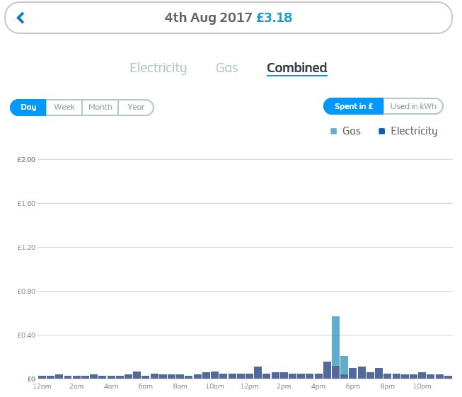
I opted for 1/2 hour reading to be captured throughout the day, the combined log is automatically uploaded daily to a remote server via the mobile network, logging into My Energy Portal (28/2/22 Portal Down)will allow you to see you consumption breakdown over time:
So, all done, its taken a few years to get and at one point I thought I would have to wait until 2020, fortunately I was wrong.
Updates
11 August 17, my mobile and online British Gas app no longer show half-hourly usage, instead they show seasonal overall consumption, I have raised a service ticket to see if this can be returned to as it was, the old IGT card was mentioned during my converstaion with the service desk and I said I have a screen grab posted to the internet, so I know it was working!!
16 August 17, Yeah!! My Energy portal is back working showing 1/2 hourly usage figures.
4 September 17, noticed that the gas reading was not being updated on the remote display after 30 minutes of use, it to update with all the reading the next day and then at random times the gas icon would light, BG coming out on 2 Nov 17 to replace the display.
3 November 17, indoor display changed by BG but he could not wait the 30 minutes to see if gas registered on the display, unfortunately it still doesn’t update.
14 November 17, spoke to BG Smartmeter department on 0333 2029821 and there is nothing that can be done to get my display to show gas readings every 30 mins, they are working on the issue, but as yet there is no fix. Meter consumption readings are updating via the Vodaphone network ok.
I’m disappointed as the display does not give the functionality as advertised, but it is free so I’ve nowhere to go with this.
16 December 17, not sure if its a fluke or not, plugged the display in upstairs and after a week or so of not showing gas being used, it suddenly started working, then stopped again!
8 May 2024 – Smart Meters Upgraded
I changed energy provider to Octopus some time ago and was used to giving online meter readings on the 22nd of every month, I did notice on the Octopus App that my SMETS1 electricity meter was sending readings but this was not the case for the gas meter.
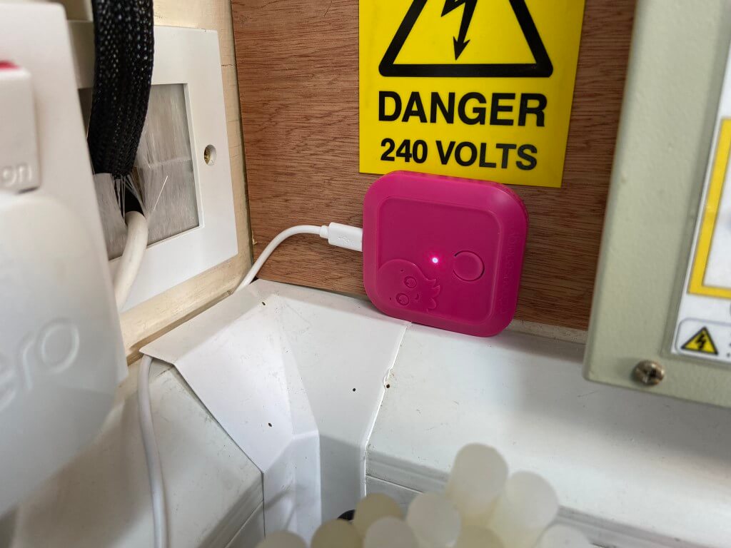
After considerable correspondence with Octopus over a protracted period of time, finally a date was fixed to replace my existing meters with SMETS2 smart meters, also I was getting a new In Home Display and I asked for a Home Mini to interface into Home Assistant.
The meter fitter was very chatty and happily answered all my questions, after conducting electrical and gas safety checks on the house, the meters were swopped out.
The SMETS1 electricity meter had a separate communications module, the new meter has this module plugged into the top of the meter making for a more compact installation.
The main difference is the display scrolls every 8 seconds, so no button to press to get your meter reading, you just wait until it shows:
Time > Date > KWh > Inactive >
No obvious changes to the gas meter apart from a slightly more angular housing.
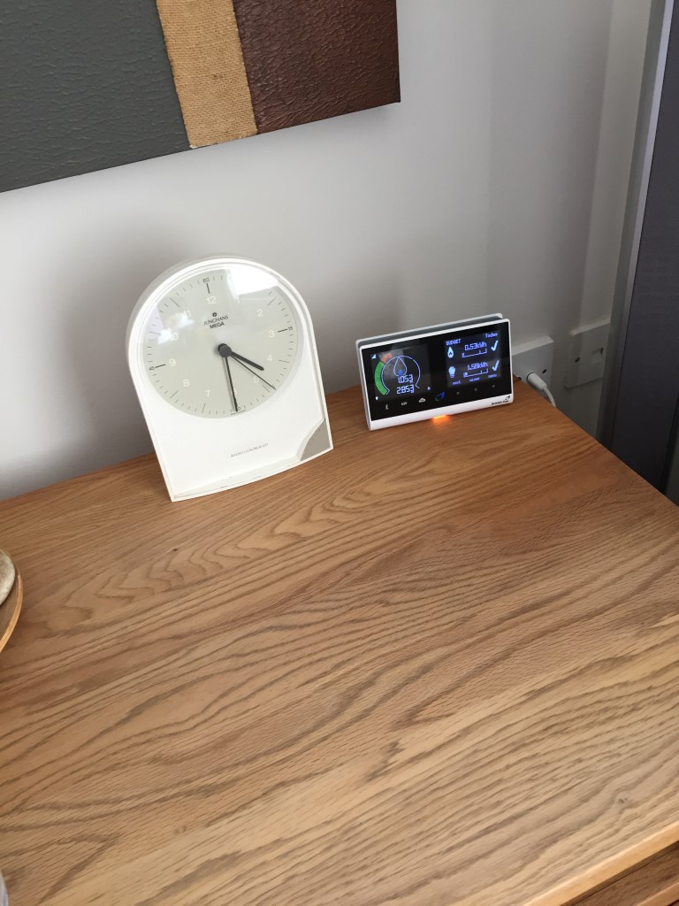
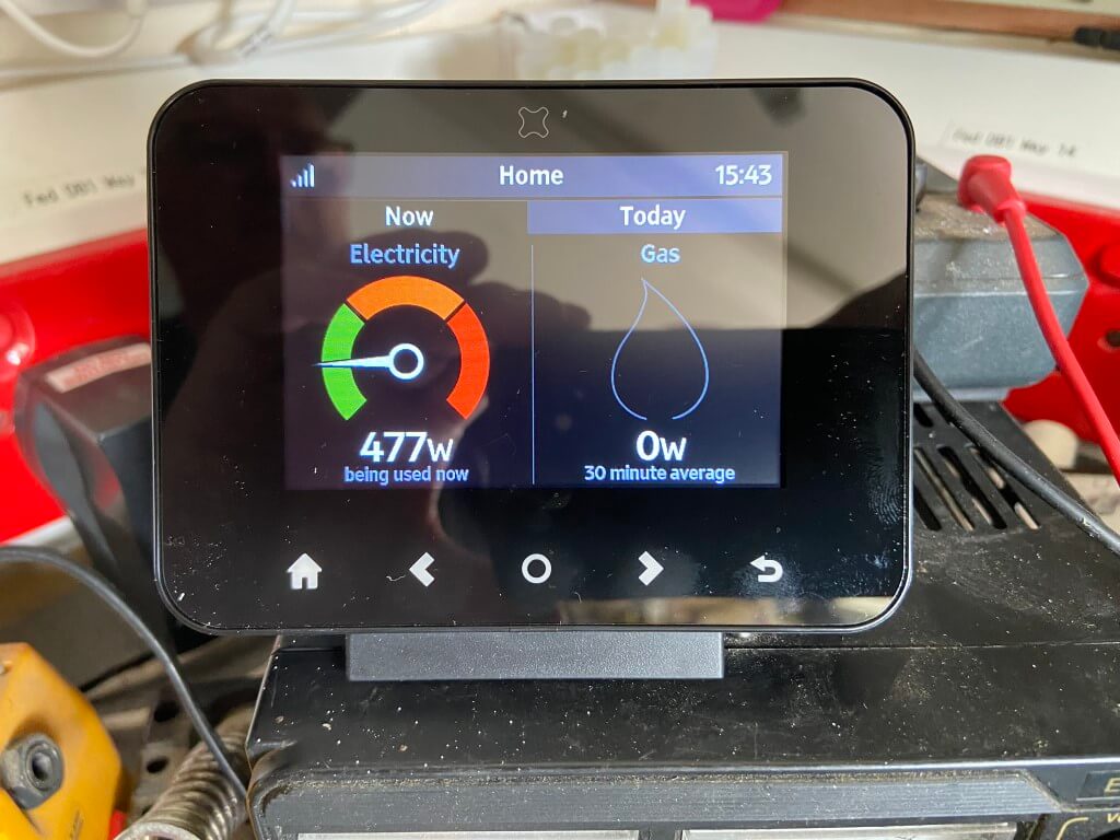
In Home Display
This is a third party item, supplied by Octopus but made by geotogether.com, a Geo Home App is available for the In Home Display and it uses an inbuilt Wi-Fi module accessed via the settings menu, once a geo home account is setup, your mobile device will show all the readings on the App.
This works really well as the signal strength drops significantly is I move the In Home Display fore than a few feet away from my meter.
The Octopus App also shows the meters data, with or without the In Home Display.
The Home Mini has been developed by Octopus and enables greater information to be downloaded about your energy usage, I use Home Assistant and this interfaces perfectly.
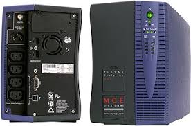
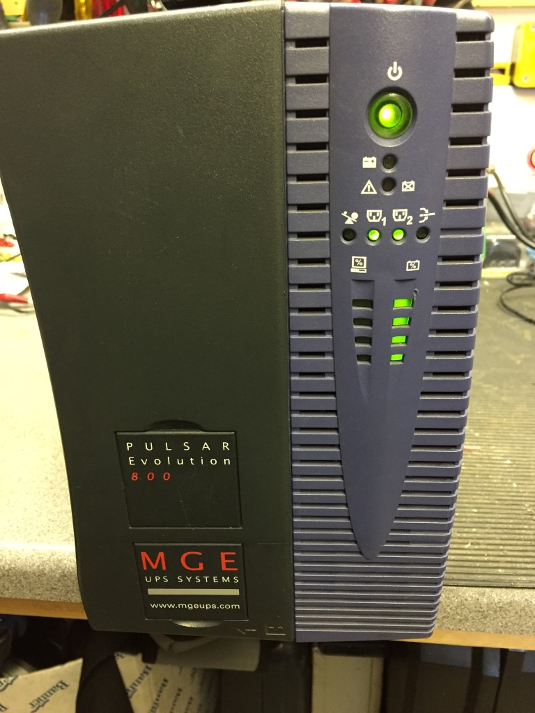
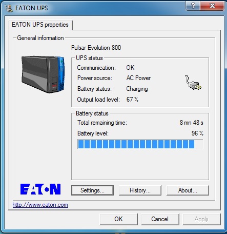
I have had an MGE Pulsar Evolution 800 Uninteruptable power Supply for about 8 years through which my computer and other sensitive kit is fed and I serviced it with new batteries in January 17.
This UPS delivers 800VA or 520 Watts (Calculator for Watts/VA HERE.) and is at 67% loading when in use, giving a back up time of 9m 35s, which is more than adequate for my needs.
In early February the UPS stopped working completely, no output or indication of power in, the one I have cost £10 second hand off eBay so I couldn’t complain when it stopped working.
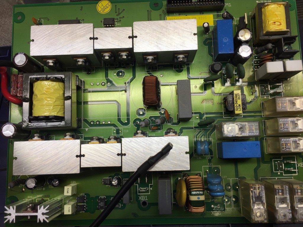
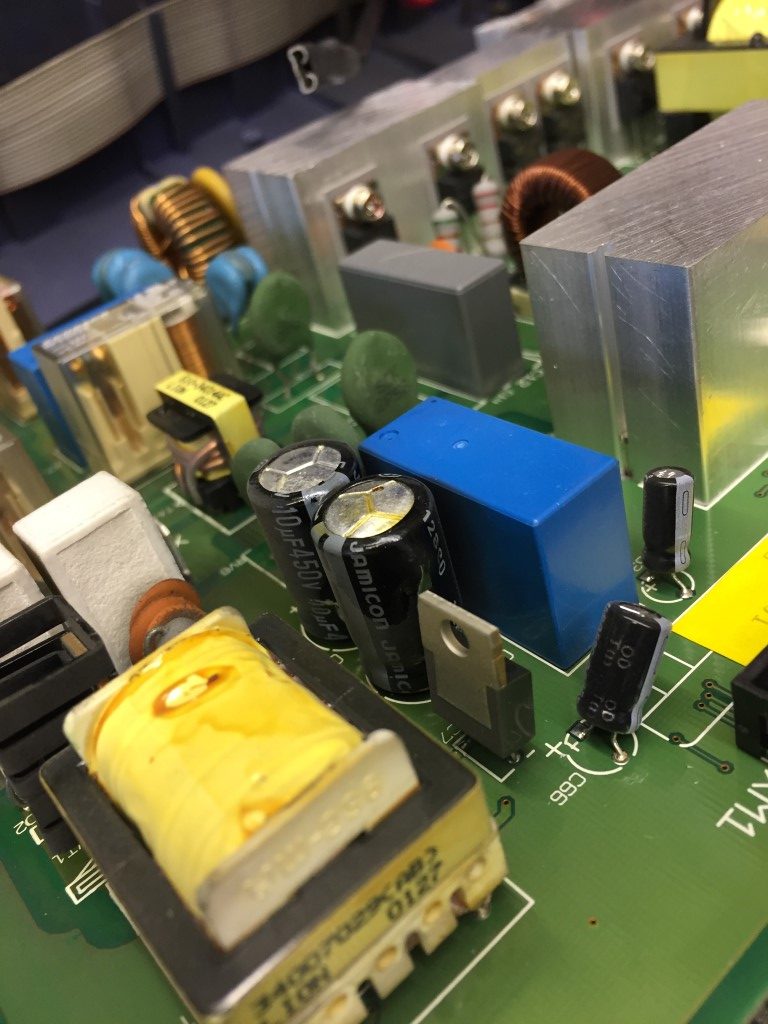
Before looking for another replacement, I opened it up the check for the obvious, such as internal fuses blown or PCB track damage, looking near the power regulator stage I noticed a bulging capacitor which is a sure sign that it has failed.
Mother Board
Bulging Capacitors
Everything else passed a visual inspection, so I bought a pack of 5x 10uF 450v 105c capacitors from eBay for £1.59.
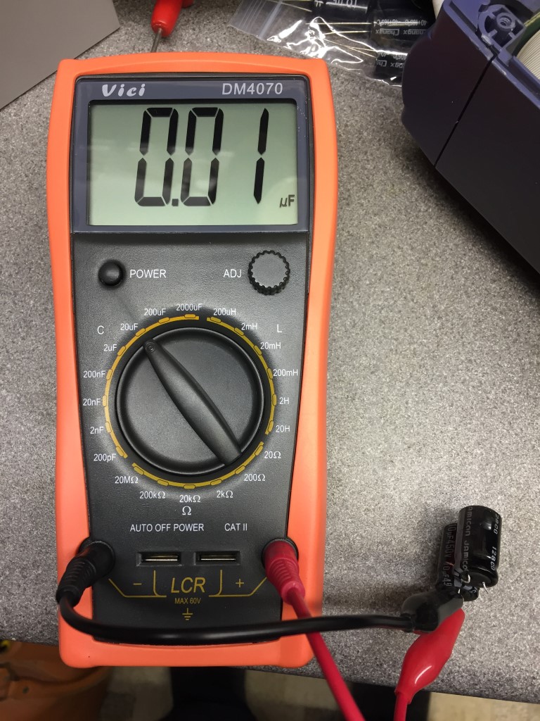
After changing the capacitors, I measured the old capacitors and they had both failed as the meter should be displaying 9.5uF to 10.5uF.
Faulty capacitors
Once reassembled, I powering up the UPS after inserting the batteries, the UPS kicked in to self-test mode and was working 🙂
Everything is back in place working and I have software monitoring its performance and everything is looking good so far.
A copy of the Pulsar Evolution 800 manual is HERE.
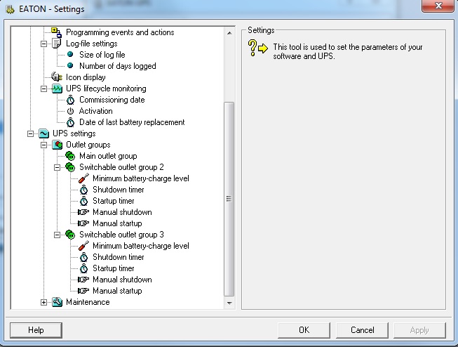
Solution Pac software for the UPS can be downloaded from HERE.
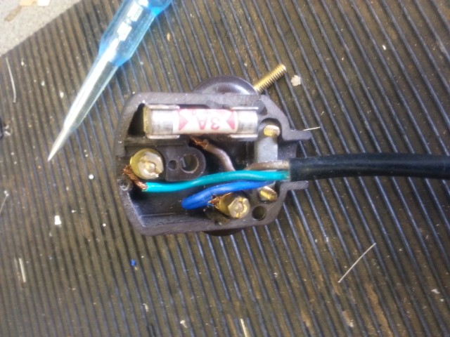
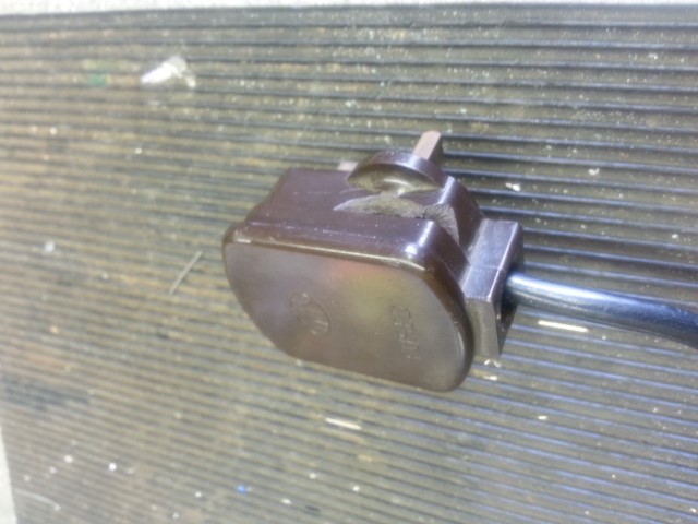
I was given a 13.8v Power Supply Unit at a local radio rally so thought I’d check it out, first job was the plug top, this is what I found;
I rewired the plug and used the optional extra strain relief, this was the before picture.
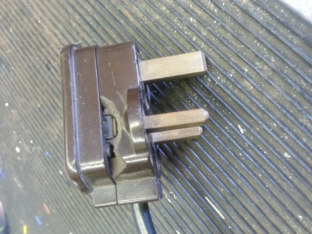
It was only after I put the plug back and inspected it, that I noticed the condition of the outside of the plug and the lethal exposed conductor.
Once a new plug was fitted the PSU worked fine, just a cautionary tale, always double check everything from a rally.
A blog about stuff that interests me or I have done.
We use cookies on our website to give you the most relevant experience by remembering your preferences and repeat visits. By clicking “Accept All”, you consent to the use of ALL the cookies. However, you may visit "Cookie Settings" to provide a controlled consent.
This website uses cookies to improve your experience while you navigate through the website. Out of these, the cookies that are categorized as necessary are stored on your browser as they are essential for the working of basic functionalities of the website. We also use third-party cookies that help us analyze and understand how you use this website. These cookies will be stored in your browser only with your consent. You also have the option to opt-out of these cookies. But opting out of some of these cookies may affect your browsing experience.
Necessary cookies are absolutely essential for the website to function properly. These cookies ensure basic functionalities and security features of the website, anonymously.
Cookie
Duration
Description
_GRECAPTCHA
5 months 27 days
This cookie is set by the Google recaptcha service to identify bots to protect the website against malicious spam attacks.
cookielawinfo-checkbox-advertisement
1 year
Set by the GDPR Cookie Consent plugin, this cookie is used to record the user consent for the cookies in the "Advertisement" category .
cookielawinfo-checkbox-analytics
11 months
This cookie is set by GDPR Cookie Consent plugin. The cookie is used to store the user consent for the cookies in the category "Analytics".
cookielawinfo-checkbox-functional
11 months
The cookie is set by GDPR cookie consent to record the user consent for the cookies in the category "Functional".
cookielawinfo-checkbox-necessary
11 months
This cookie is set by GDPR Cookie Consent plugin. The cookies is used to store the user consent for the cookies in the category "Necessary".
cookielawinfo-checkbox-others
11 months
This cookie is set by GDPR Cookie Consent plugin. The cookie is used to store the user consent for the cookies in the category "Other.
cookielawinfo-checkbox-performance
11 months
This cookie is set by GDPR Cookie Consent plugin. The cookie is used to store the user consent for the cookies in the category "Performance".
CookieLawInfoConsent
1 year
Records the default button state of the corresponding category & the status of CCPA. It works only in coordination with the primary cookie.
PHPSESSID
session
This cookie is native to PHP applications. The cookie is used to store and identify a users' unique session ID for the purpose of managing user session on the website. The cookie is a session cookies and is deleted when all the browser windows are closed.
viewed_cookie_policy
11 months
The cookie is set by the GDPR Cookie Consent plugin and is used to store whether or not user has consented to the use of cookies. It does not store any personal data.
Functional cookies help to perform certain functionalities like sharing the content of the website on social media platforms, collect feedbacks, and other third-party features.
Performance cookies are used to understand and analyze the key performance indexes of the website which helps in delivering a better user experience for the visitors.
Analytical cookies are used to understand how visitors interact with the website. These cookies help provide information on metrics the number of visitors, bounce rate, traffic source, etc.
Cookie
Duration
Description
_ga
2 years
The _ga cookie, installed by Google Analytics, calculates visitor, session and campaign data and also keeps track of site usage for the site's analytics report. The cookie stores information anonymously and assigns a randomly generated number to recognize unique visitors.
_ga_92TJCVGJP2
2 years
This cookie is installed by Google Analytics.
_gat_gtag_UA_48800884_1
1 minute
Set by Google to distinguish users.
_gid
1 day
Installed by Google Analytics, _gid cookie stores information on how visitors use a website, while also creating an analytics report of the website's performance. Some of the data that are collected include the number of visitors, their source, and the pages they visit anonymously.
CONSENT
2 years
YouTube sets this cookie via embedded youtube-videos and registers anonymous statistical data.
is_unique
5 years
StatCounter sets this cookie to determine whether a user is a first-time or a returning visitor and to estimate the accumulated unique visits per site.
is_visitor_unique
2 years
StatCounter sets this cookie to determine whether a user is a first-time or a returning visitor.
sc_is_visitor_unique
2 years
StatCounter sets this cookie to determine whether a user is a first-time or a returning visitor.
Advertisement cookies are used to provide visitors with relevant ads and marketing campaigns. These cookies track visitors across websites and collect information to provide customized ads.
Cookie
Duration
Description
NID
6 months
NID cookie, set by Google, is used for advertising purposes; to limit the number of times the user sees an ad, to mute unwanted ads, and to measure the effectiveness of ads.
VISITOR_INFO1_LIVE
past
A cookie set by YouTube to measure bandwidth that determines whether the user gets the new or old player interface.
YSC
session
YSC cookie is set by Youtube and is used to track the views of embedded videos on Youtube pages.
yt-remote-connected-devices
never
YouTube sets this cookie to store the video preferences of the user using embedded YouTube video.
yt-remote-device-id
never
YouTube sets this cookie to store the video preferences of the user using embedded YouTube video.
yt.innertube::nextId
never
This cookie, set by YouTube, registers a unique ID to store data on what videos from YouTube the user has seen.
yt.innertube::requests
never
This cookie, set by YouTube, registers a unique ID to store data on what videos from YouTube the user has seen.