
Updated 10 November 2025
This blog is from 2014 updated in Feb 2018 and refreshed in July 2022.
A few years ago just before Christmas we had an extended power outage, not only didn’t the telly work :-(, but all the food in the fridge/freezer was nearly spoiled which would have been a disaster, it was at that point I decided to install an external power inlet point for a petrol generator and some form of switching.
I decided early on that I only needed the essentials to be on the generator backup, this included the heating, lighting, kitchen power circuit and cooking, it was important that I confirmed which circuit breaker control which circuit, this is important as I need to isolate high current consuming circuits so as not to overload the generator when online.
The generator I bought was a Honda 3kVA manual pull start unit off eBay (it later transpired that it wasn’t a genuine Honda, you’ve got to love shysters), which should be plenty big enough, if we need to heat water for hot drinks we’ll use the gas hob kettle rather than the electric one so as not to overload the genny, I can keep an eye on actual consumption due to a digital power monitor which is incorporated into the transfer switch enclosure.
As the generator is a manual pull start their was no point having an automatic power transfer switch, so I built a manual one.
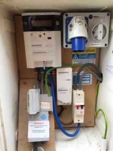
So, outside in the meter cupboard is a 16A switched male socket inlet, this has been modified with a power indicator which illuminates when the generator is running, the generator plugs into this external outlet via small lead, two things to note, first that the petrol generator is outside so that fumes can’t get into the house and secondly that the power lead from the generator to the house uses a female socket to ensure that no exposed pins can be touched with the generator running, removing any shock risk.
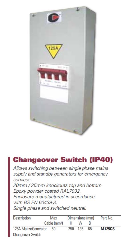
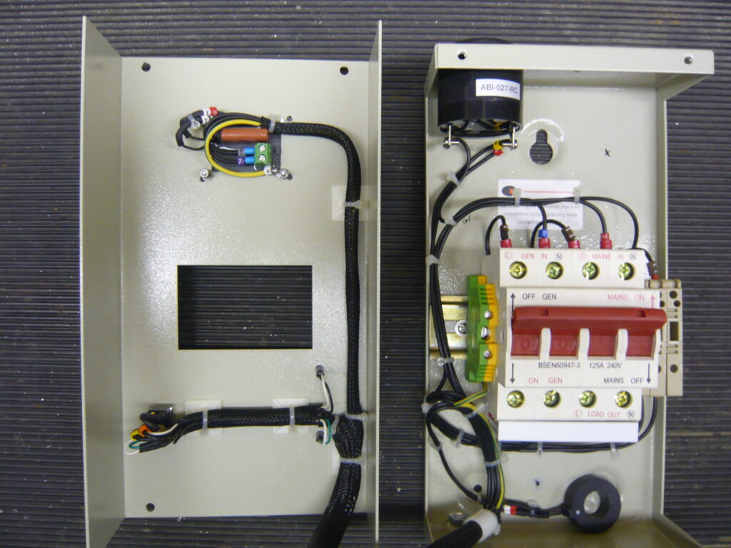
From the external socket a 4mm cable feeds into one side of a power transfer switch, this switch has a capacity of 125 amps and is a break before make type, this will ensure that it is not possible to back feed power to the generator from the utility supply during the manual switching operation.
The supply from the utility company also go to this transfer switch, the output of the switch goes to the consumer unit and from here to each of the circuits in the house.
Operation – under normal conditions, the transfer switch is set to Utility supply, this is confirmed by a green 230vAC LED wired directly across the supply via a1A fuse.
On a sustained power outage, the generator is hooked up and started, the switch on the external socket inlet is turned to ON and the Red generator power available LED is lit, (the 230vAC LED is wired directly across the generator supply at the switch via 1A fuse).
Non essential circuit breakers in the consumer unit are turned to the OFF position, once done, the transfer switch generator power available LED is checked, and if still available, the transfer switch is operated to import power to the consumer unit from the generator.
As the transfer switch is in the garage, I would not know if the Utility power had been restored, I therefore fitted a 230vAC buzzer across the Utility supply via a switch, restoration of utility supply is indicated by an audible tone which obviously is switched OFF in normal Utility power operation.
To check that the generator is not being electrically overloaded, an ACM20 panel meter was fitted, this displays, amongst other things is power (Watts) being drawn, which is very useful for this monitoring function.


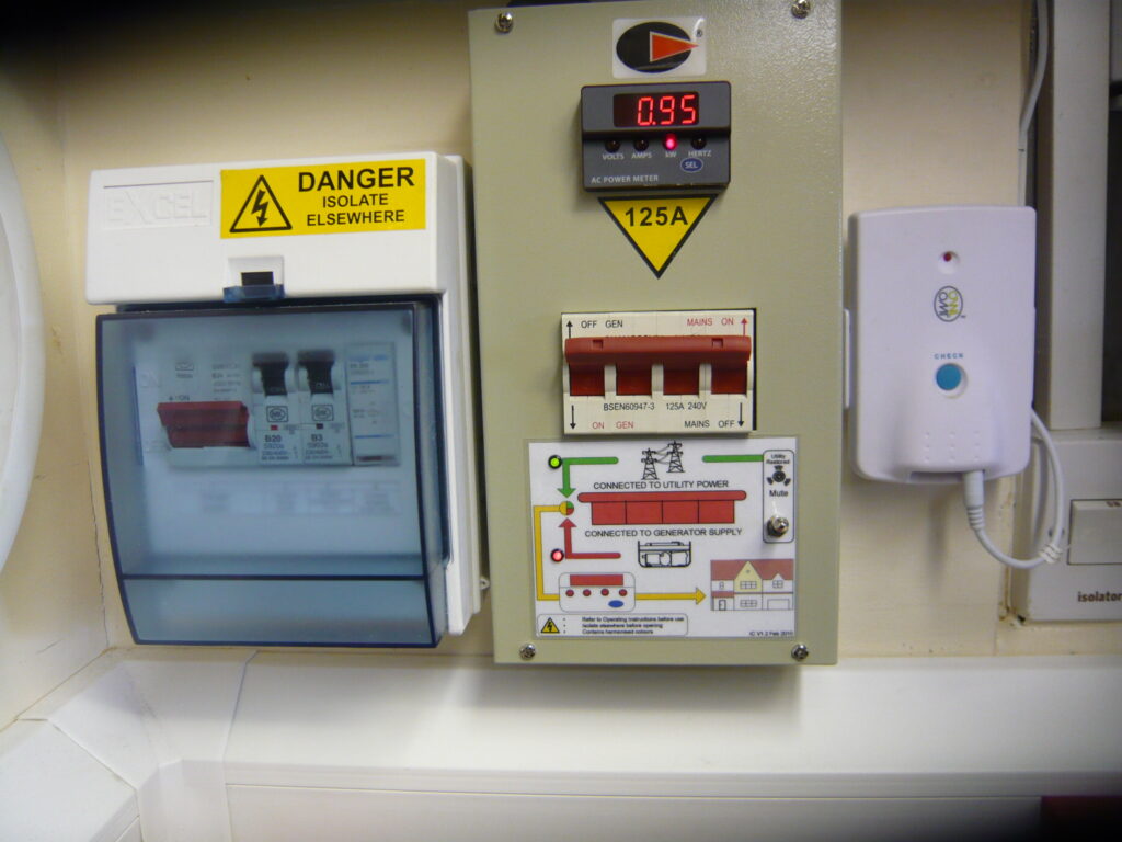


System on test, instruction by the consumer unit, give the start-up and shutdown process including which breakers to turn off before changing over, the transfer switch panel meter is used for monitoring load to make sure the generator is not overloaded.
Update
17th December 2022 – I’ve noticed over a few months that the ACM20 display has been acting weird, and today it finally gave up giving me believable readings, so a new one is on order from Mouser.co.uk for the sum of £80.47.
31 January 2023 – Taken a while but finally got round to replacing the original meter, the details of the new one are:
- www.murata-ps.com
- ACM20-4-AC1-R-F-C
- Part Number – 4900204
The only issue I had was getting the Current Transformer wires the right way round as I had to extend them, you know if its wrong when the Wattage stays at zero!
Enjoyed reading this. Thanks!
How can you tell if a Honda is genuine or not?
Hi,
I found out mine wasn’t genuine when I rang a local Honda dealer and he asked me for the serial number, he told me that it was a fake 🙁
Nice tips. Thank you for sharing this topic to us.
Fantastic blog, great transfer switch. Did you make that yourself or is this manufactured by company. Would love to find out a little more. Can you provide a little detail about it?
Hi Wes,
Glad you liked the blog, the transfer switch was bought pre-fabricated but the switch is available from here – https://a1electrics.com/circuit-protection/213/125a-230v-changeover-switch-mains-generator.html and just requires a suitable enclosure.
Ian,
It’s a great setup, really like it, well done!
I think like you I’m going to have to build my own manual transfer switch enclosure as I can’t find a manufactured manual transfer switch with voltage presence indication.
I like the idea of being able to know the grid or the generator is live so I know it’s good to switch back to grid when it’s back on after a blackout/power cut.
Would you mind sharing some of the details on how you did that part of your design. It really is a great idea and like the idea of also incorporating a digital power meter as well, great!
Hi Wes,
I’ve added a bit more information to the blog and found a better resolution picture of the inside of the transfer switch.
The switch from the manufacture came in an enclosure, but like you, it needs some modification to make it more ‘functional’, I don’t have a diagram to hand as all I did was wire some 230vAC LEDs across the Utility and Generator connections of the transfer switch (LEDS are fused down).
The Utility supply available buzzer was again wired across the incoming supply via switch which is only ever turned ON when on generator backup supply.
The panel meter is an ACM20 and is very simple to connect, the link gives full instructions.
Let me know how you get on.
Hi Ian, this is fantastic, thanks for taking the time to update your blog post with the detailed info and higher resolution photo, this is a massive help. I think I should be able to work my way through this. Thank you.
I do have a question, that I would really like to hear your thoughts on. Your supply from the DNO looks a lot like mine. And I am curious to know what your earth arrangement is when you are transfer switched onto the generator.
My main worry would be that if the grid fault is a cable down then there is no longer a route to earth. But my biggest worry is that the RCD’s in my consumer unit may not work correctly as there is no Neutral to Earth. Have you configured anything on the generator side for this and do you also use a earthing rod?
Hi Wes,
Great question.
This is the big problem with TN-C-S (PME), the loss of the Protective Earth/Neutral conductor could leave the installation voltage ‘floating’, unless the break from the distribution point is adequately earthed along its length, I chose to assist this, by installing a 8′ earth rod connected to the main earth terminal by a 10mm2 conductor.
When the generator is in use, the DNOs earth remains connected due to the nature of supply, only the Neutral and Line is switched via the transfer switch, selected consumer unit RCBOs are left ON whilst the majority are turned off, those circuits which are ON, have non-critical appliances switched off to reduce load.
The RCBOs left ON are: IT Router, Kitchen Ring for the fridge, Downstairs Ring for the TV 🙂
Regarding RCDs, as I’m in control of the installation during this abnormal situation and the majority of things left ON will be fixed Class2 appliances, I will manage the risk which I perceive to be very low.
It is a judgement call based on your circumstances.
Great writeup and love the mods to the transfer switch. Are those additions to the transfer switch fused down via din rail fuses to the right?
Regarding your latest comment
Regarding RCDs, as I’m in control of the installation during this abnormal situation and the majority of things left ON will be fixed Class2 appliances, I will manage the risk which I perceive to be very low.
With the inclusion of earth rod what risks are there likely to be?
Also is your generator floating neutral or linked to earth (at the gen or at the inlet box)?
Hi Michael,
Well spotted, yes the display led’s and power display are individually fused down.
The only risk I could see would be that of a lost network neutral upstream of my property causing a localised outage, rather than a power cut. This scenario could lead to excessive neutral currents from other connected properties flowing through my earth rod, and my presumption is that it may have a possible adverse effect on the RCDs operation.
If I’m way of with my theory, please let me know as I’m always willing to learn and things do move on.
The generator is neutral/earth linked in the plug to give a fixed reference.
Thanks for your feedback and I agree with your theory on the lost neutral in the area, although as you mentioned its within your acceptable risk factor.
One further question I did have was regarding the interlock socket, did you modify that to be an inlet as it looks a perfect fit? I cant quite tell the part number of the inlet (the interlock looks to be a gw66004)
Again, really love the mods you did to that changeover switch and will be taking inspiration from it
Hi,
I butchered the gw66004 to change its gender from female to male rather than have a ‘suicide lead’, the interlock feature was a casualty unfortunately, the only other modification to the gw66004 was the addition of a 230v indicator lamp which illuminates when the generator is running.
The indicator lamp is connected directly to the rear of the male outlet, the idea being that I know the generators output is available for switching through to the transfer switch.
For info – Bigclive on YouTube did a stripdown of an automatic transfer switch from China which looked interesting.
Thanks for the update, I did see bigclives transfer switch video and do see this often on Amazon/eBay but honestly I just don’t trust it to be able to carry anywhere near the current the main fuse is rated at, even 50amps I’d be surprised. At least with your setup you have a trusted change over switch that should have no problems with the rated current and for the sake of safety if its manual its probably for the better.
Agreed, I thought it was a novel solution but much prefer a manual switch, no chance of ‘stiction’.
Let me know how you get on.