Tag Archives: pyronix

Pyronix Euro46 Alarm Automatically Locking the Garage Door

3 January 2023

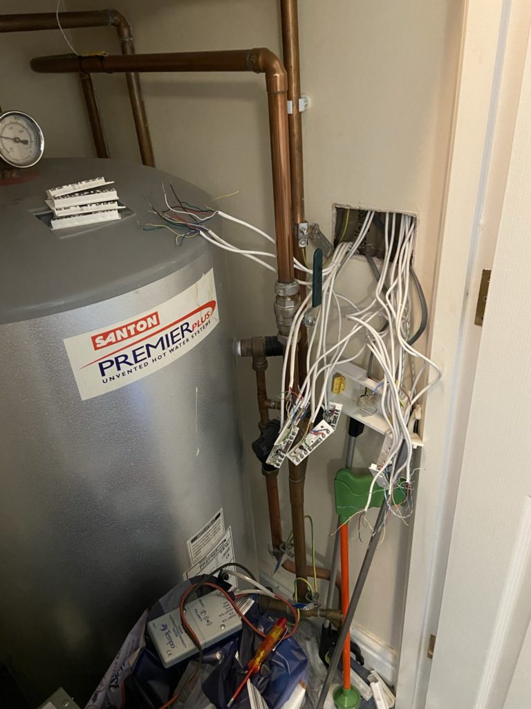
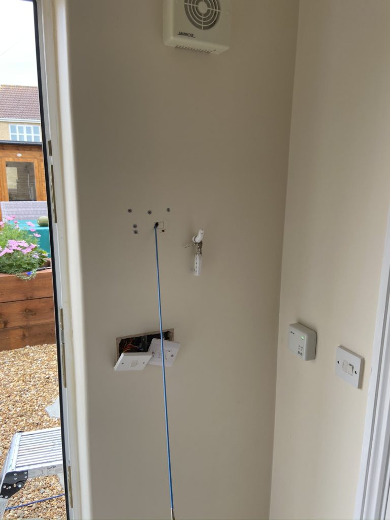
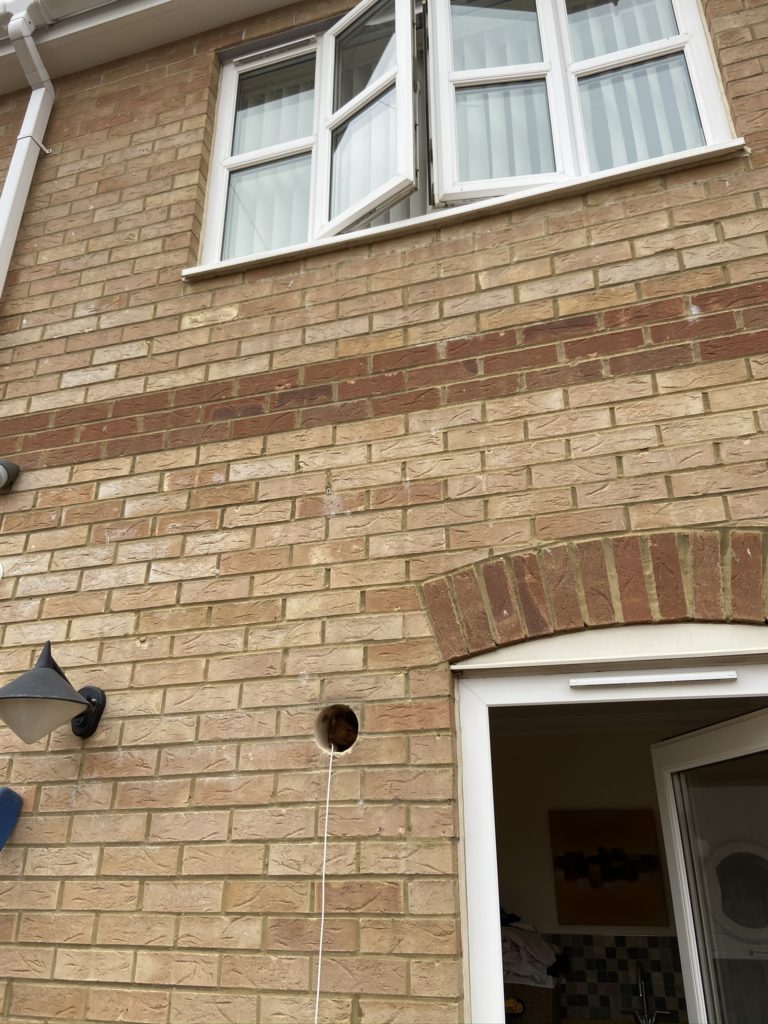
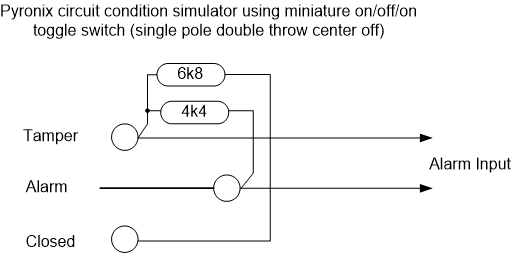
When I installed my Pyronix Euro46 house alarm, the garage was designed as a separate area allowing it to be set independently of other areas, to confirm final setting and to start the entry timer, a small lever microswitch was fitted to the sliding locking mechanism on the garage door.

Microswitch to detect lock position

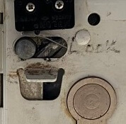
When the door is locked, the pin is over to the right; the picture above shows the door in the unlocked state.

This arrangement works really well, the biggest problem is when I come to set the alarm from within the house, only for the alarm to indicate that I had forgotten to lock the garage door, meaning I have to go outside to the front of the house and lock the door, a real niggle 🙂

The image shows that the garage door is not locked, but now pressing the Lock Garage Icon will do this for me.

Locking Process

This is in two parts, the first being how the mechanically lock the garage door and the other is how electrically this would work with the alarm system.

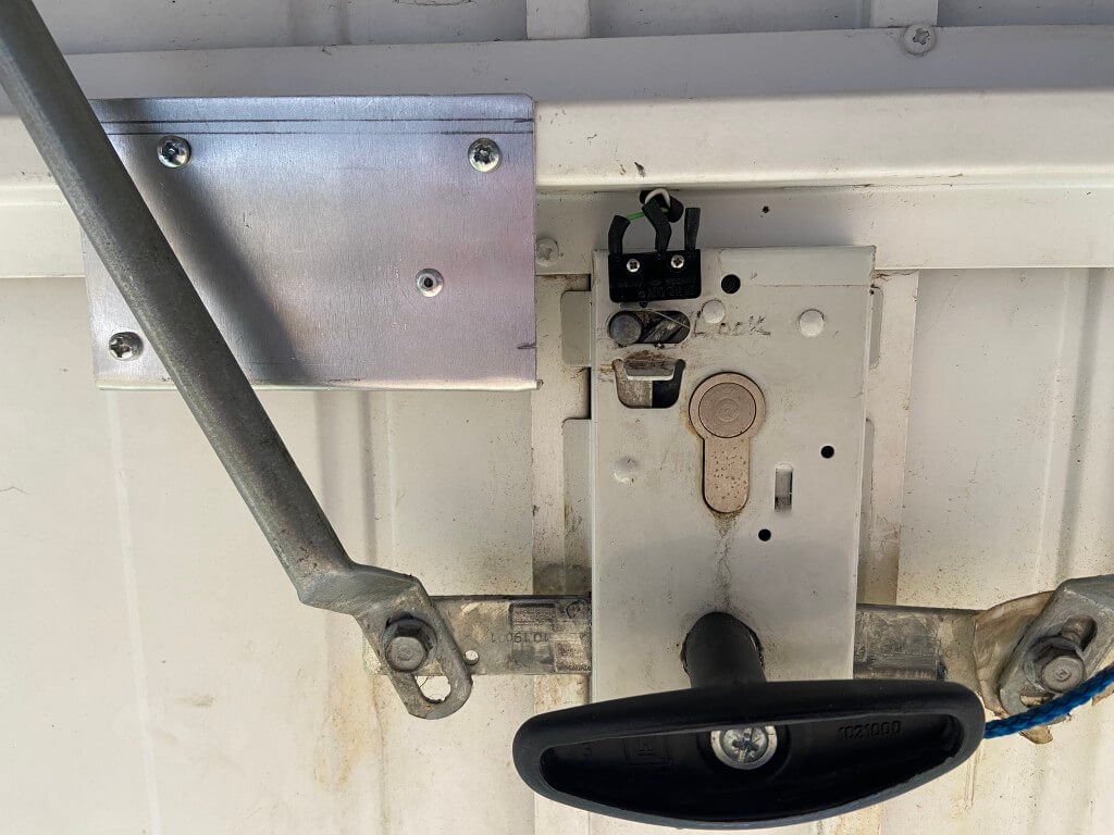
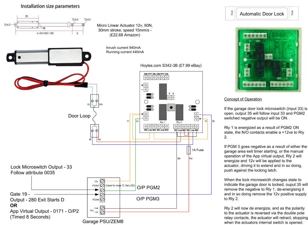
The garage door can be locked with a key from the outside or by sliding the internal locking pin to the right, sliding the pin takes quite a force to manually move, so I took a punt and bought a 12v Micro Linear Actuator from Amazon, this has a 30mm stroke and can apply a force of 60N (6kg) and turned out to be ideal.

I mounted the actuator on a small sheet of 1.5mm aluminum and with the actuator fully extended, aligned the end of the arm to the full throw of the locking pin and tested operation with a battery, once happy, I used self tapping screws and affixed the aluminum to the garage door cross member.

The wires from the actuator and microswitch are taken off the door by a flexible door loop.

The triggering of the actuator was the next part to look at.

The actuator has an inbuilt limit switch, stopping the motor at each end of the arms travel, to operate, apply 12vDC and this will extend the actuators arm, reversing the 12v polarity will causes the actuator arm to retract and stop.

I could have physically connected the actuator arm to the locking pin enabling me to both lock and unlock the door electrically, the only problem with this is that the external euro lock would no longer work, as the locking pin would be held in position by the actuator arm which cannot be manually retracted.

Actuator Logic

  • The garage door to automatically lock when setting the alarm,
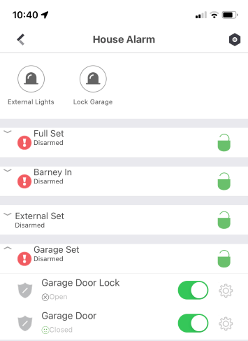
  • Ability manually trigger the locking actuator from the ProControl+ App on my phone,
  • If the door is locked the actuator has no need to operate.

Programming Euro46

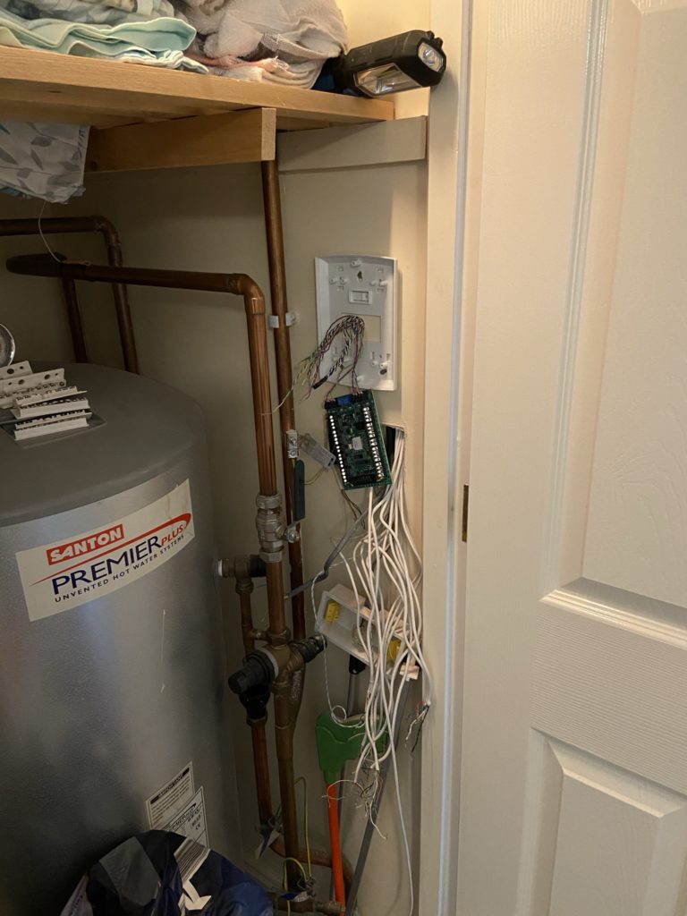
The Pyronix Euro46 has a comprehensive number of programmable outputs and options which made the actuator logic easy to setup via the ‘InSite’ software.

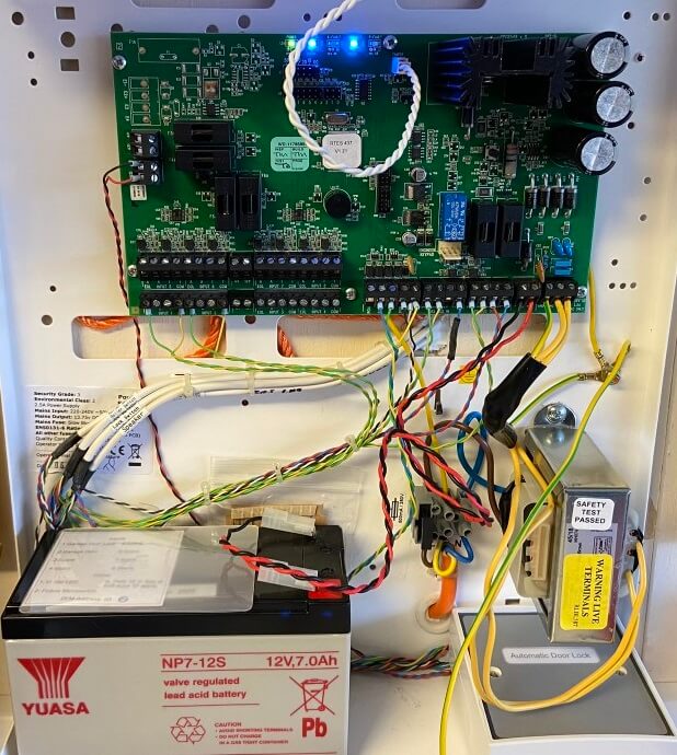
The garage has a PSU/ZEM8 which has 4 programable outputs, I used two of these Outputs for this project, Outputs 2 & 3.

Output 2 was programmed to ‘Follow’ (Output type 35) the switch state of the lock microswitch (Input 33), if the lock is closed, the Output would go LOW enabling Relay 1 to energize, the contacts of this relay apply or remove a 12v positive to the trigger of Relay 2.

Output 3 was programmed as ‘Gate’, the gate is comprised of a combined OR logic within the panels software.

Output 3 would go LOW enabling Relay 2 to energize if the positive from Relay 1 was available.

Output 3 LOW conditions-

  • if the Exit time starts for Area ‘D’ (Output type 280),
  • OR
  • the Apps virtual Output is triggered (Output 0171 timed for 8 seconds).

Relay 2 simply changes the polarity of the 12vDC to the actuator, in the relays OFF state, 12v is applied to retract the arm, in the ON state the arm extends, once Relay 1 operates, Relay 2 will drop out causing the arm to retract.
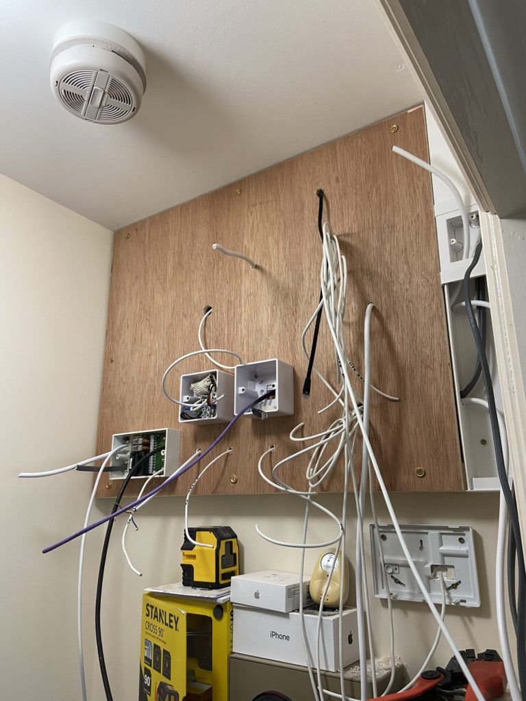
Relay Wiring

All connected up with the door lock relays housed within the PSU/ZEM8 enclosure, 12v supply to the actuator is fed from the PSU and further fused down to 1A.

Operation

Pyronix Euro 46 Home Alarm Installation

Front of property showing external sounder and CCTV cameras with infra-red illuminators on.

Background

I installed my original alarm system in 2006 which was monitored by Custodian Alarm Receiving Centre with a police response. The Control & Indicating Equipment was Scantronic 9851 with two remote keypads, all detection devices throughout the property were hardwired and both front and rear sounders were live.

The end station was installed out of the way in the loft:

I decided in March 2020 to ‘get back on the tools’ and install a new hybrid system with App functionality, the system also had to be remotely programmable, have flexible circuit input/output attributes to allow for third party integration and have a comprehensive range of detection and system devices.

Looking at the marketplace range of products, training packages offered by the manufactures and distribution availability, I opted to install a Pyronix Euro 46.

I must admit to not liking the old CastleCare range as they looked a bit too clunky for a domestic environment when compared to their competitors offerings, hence, I originally installed a Scantronic panel, however, after installing it, I really like the no nonsense, intuitive keypad and the area LEDS showing the set status is really handy as a quick visual verification that the system is armed.

System Topology

The wiring architecture is very straight forward with a data buss from the blind end station going to either or Zone Expansion Modules (ZEM8), Wireless Expansion Modules (ZEM-32WE), Output Modules (EURO- OEM8R8T) or Keypads or a mix and match of these to suit the systems design configuration.

In my case I needed two 8 circuit zone expanders, 1 output module, 4 keypads, 1 wireless 32 zone expander and 2 remote key fobs, as this is my test system as well, one of the keypads is local to the panel acting as the engineers keypad.

The Scantronic system used resistors in each detector enabling a Fully Supervised Loop, this means that two wires can monitor the following circuit status:

  • Device Open
  • Device Closed
  • Tamper – Open Circuit
  • Tamper – Short Circuit
  • Detector Anti-Mask

Installation

I decided to bring the end station out of the loft, two main reasons for this, the first being access for servicing and the second is the elevated temperatures in the summer are not healthy for batteries and will shorten their life.

I have a small unused cupboard which is ideal so the cabling was re-routed from the loft, or new runs installed.

Cables ready for second fixing.

Access to zone expansion modules is less critical, so one ZEM8 is in the airing cupboard and others modules are in the loft, as below.

These pictures below show the installation of a ZEM8 –

The house was prewired for an alarm system during construction with the intention of the End Station going in the airing cupboard, as this was not the case when I first fitted the system, all cables were extended using junction boxes.
ZEM8 mounted on the wall with detection circuit cables entering via rear access slots.
Completed ZEM8 with circuit descriptors clearly visible to aid fault finding or servicing.

The control equipment is able to monitor all ZEM8 parameters, such as voltage, circuit status and circuit resistance for remote diagnostics or virtual servicing.

The end station was mounted on a stand off board, this board was also home for my external GJD lighting system which is integrated into the alarm system along with CCTV recording and notification.

Smoke detectors were incorporated into the alarm system after a modification to a interlink monitor, details are HERE.

Completed setup, comprising a 3A Power Supply Unit, Euro 46 end station, relay output expansion module, external lighting end station and Sonoff external lighting override module.

I’ve not gone into detail regarding the type and specific location of detection devices for obvious reasons, that said, adding devices to the system is incredibly easy and the programming using Pyronix InSite UDL software is a doddle once you have an understanding of their menus and command functions.

As I had not used Pyronix equipment before, I made a circuit test switch box and explored on the bench all the programming options of the euro 46 before I started my system swop over, this worked really well for me, so money well spent in making it.

Details of the circuit input test box : HERE.

Tricky Keypad Install

One aspect of the installation that was a bit tricky was the cabling to the rear door keypad.

I’m old school and prefer to home run cables wherever possible, plus the option to use the keypads onboard detection circuits was not possible as this allowance had been used elsewhere, this meant that the existing rear door contacts cable could not be converted to a data buss.

I could have opted for a wireless keypad, but where would be the fun in that!

Making sure I avoided any cables in the switches safe zone, I drill at a tight angle into the cavity void.
With the external fan guard and sleeve removed, the cable was fished out from the keypad location, the external lighting sensor was then removed and the cable fished to that, before going up into the loft, all completely hidden.
All done 🙂

Sounders

The external sounders are Delta Bell, one is configured as a Self Activating Bell whilst the other is configured as a Self Contained Bell, monitoring is via an Ethernet module to the Pyronix servers (this is an annually charged service).

Conclusion

I’m very happy with the system, it is easy to use, responsive via the app and flexible, integration into Hikvision cameras is a bonus, really enjoyed this swop over, not like some I’ve been involved with in the past!

Updates

6th December 2022 – I noticed that on the furthest keypad (RKP0), that everything was fine when using the tag to set & unset, but if I were to enter the code to unset the system, the display would be very slow to respond and after a short while a Comms Error would be generated.

Although the supply voltage was within tolerance, it was in the lower band, I therefore installed a Euro-ZEM8-PSU, this now feeds the RKP directly and I also took the opportunity to remove two detection zones from the keypad and migrated them to the ZEM8, making for a more logical installation, also the ‘Area Set’ LED programmable output was also moved from ZEM address 02 to the new ZEM8.

The issue has now been resolved.

3rd January 2023 – Added automatic garage locking controlled via outputs from the Euro46 panel, blog on this can be found HERE.

Intruder Alarm Circuit Test Box

I thought I’d build a test box which will simulate the three circuit conditions of an intruder detection system (IDS), these being:

  • Circuit Tamper
  • Alarm Condition
  • Circuit Healthy or Closed (non alarm condition)

The purpose was to confirm and test the ’cause & effect’ programming of a Pyronix Euro 46 panel , the Euro 46 remote Upload/Download Software allows for logic gates to be configured, so the system ended up being very versatile.

The above picture shows the Euro 46, Keypads, Zone Expansion, Output and Wireless modules set up for testing using the multiswitch test box, the alarm system is communicating with the Pyronix Cloud server via a LAN interface, cloud configuration also allows seamless integration with the Hikvision CCTV system.

The Euro 46 has several detection circuit configurations, I chose the common value for a Double End Of Line resistor system of a 2k2 and 4k7 Ohms.

At the detection input a healthy or closed circuit, would measure a resistance value of 2k2 Ohms, if the value either exceeded or fell below this by a defined margin, the alarm panel would see this as a tamper condition, and alarm condition would present a value of 4k7 Ohms, the test box achieved the three conditions listed using the following diagram:

The above circuit presents to panel with slightly more resistance than 2k2 when healthy, however, as its within the parameters, the panel see’s this as closed with no faults.

The completed unit was built using 30 switches and I utilised an old piece of trunking to fit them in:

The circuit description label temporarily sticks over the laminated switch backing so I can fully program and test the wired circuits before installation in the future, one element I can’t test is the wireless aspect which forms a a large part of this system.