
Continuing on with the radio mast automation, this blog shows how I have wired the controller. (Part 1 is HERE)
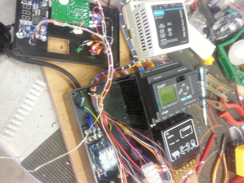
The external enclosure for the automation equipment has a plywood back board which is removable, it is to this I have mounted all the necessary bits of kit, I have loomed all the cables in with waxed lacing cord and given each conductor a unique ident for ease of fault finding.
To allow the back board to fit back into the enclosure I will have to strip everything of the board first, the 24v DC transformer and PLC are mounted on ‘top hat’ rail for ease of removal, the solar charge limiter and main control unit are held in place with wood screws.
The PLC controller is powered using 24v DC, I did try it on 12v but the output relays seemed sluggish when activated, the proximity sensors I’m using have a wide operating voltage range (9v – 30v) so these will be fed at 24v, due to the wide voltage tolerance, voltage drop will not be an issue considering the maximum cable run is 7 metres, (I’m using 8 core 7/0.2mm CSA).
The input to the PLC will be a switched high of 24v with the exception of the battery fully charged input (the board for this is affixed to the lid of the enclosure), when a charging voltage of 14.14v is reached, this will switch the battery voltage to the PLC input via a relay to cancel mains powered battery charging (link to blog on voltage relay HERE).
All cables have been marked up to aid fault finding or making additions to the control system should I need it, the image shows cables marked and ready for looming.
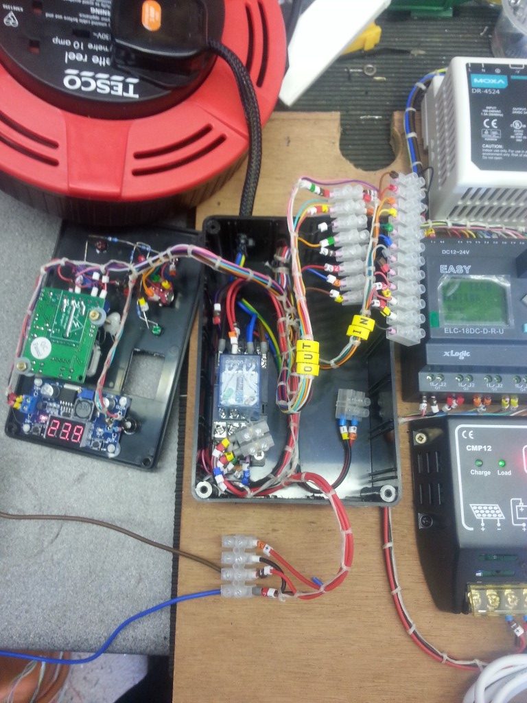
Cables loomed up with waxed lacing cord and powered up ready for bench testing.
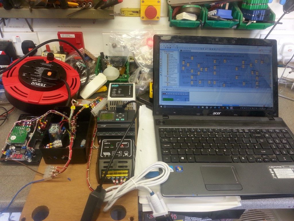
Slight tweak to the PLC program to invert the Hall Effect limit switches, for testing purposes the run on timers were set at 5 seconds, after timing the raising and lowering of the mast with a fully charged battery, the correct timings have now been uploaded.
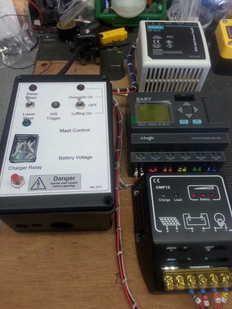
Phew!, the lid fits on the controller 🙂 and everything seems to work!
30 May 16 – I decided to use the enclosure which houses my Easy Rotor Control as the place to fit the indicators and remote switches to control the mast from the shack as it had plenty of room.
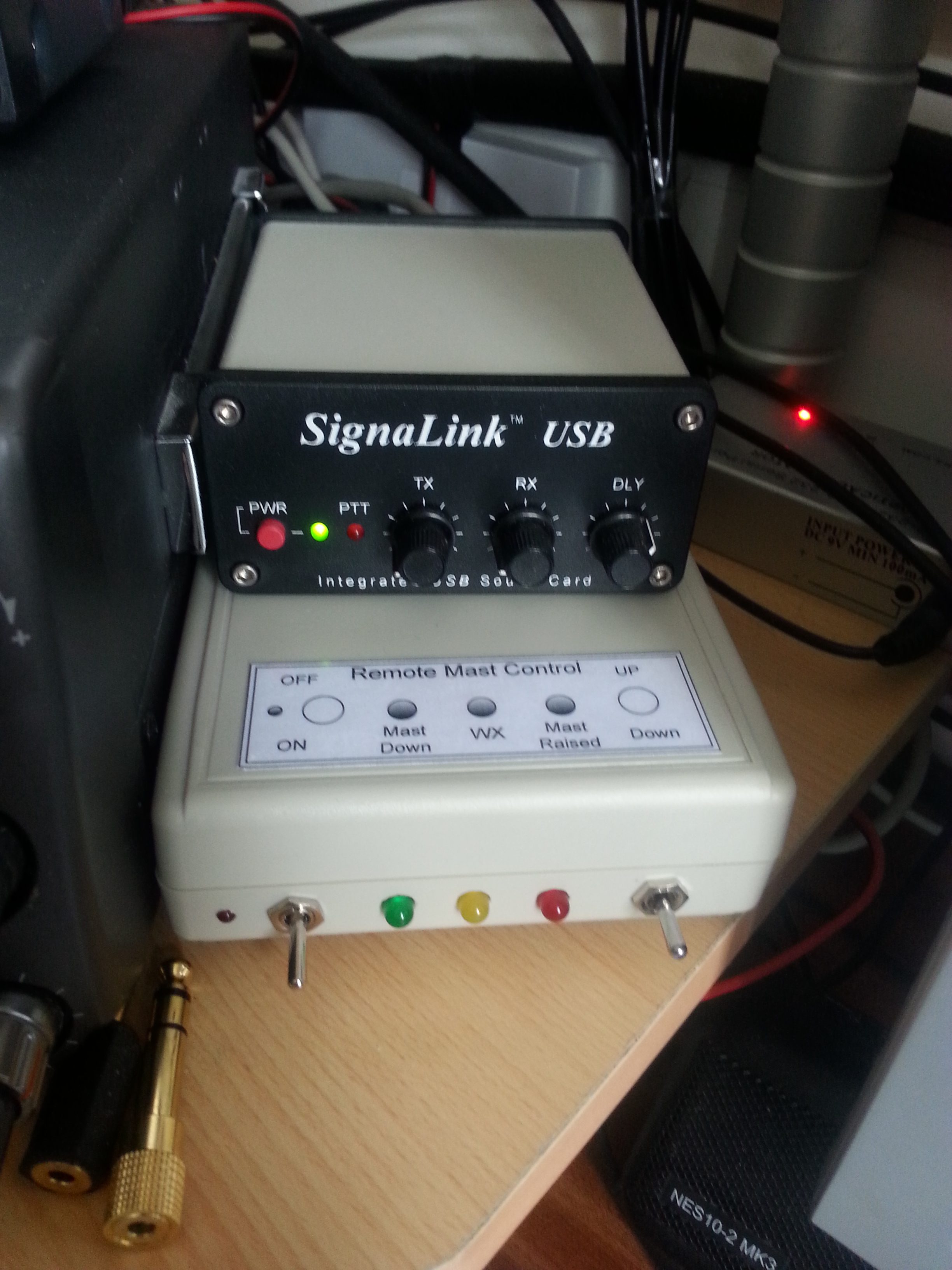
From Left to Right – The main On/Off switch is the first switch, in the ON position a small LED to the left of the switch will be lit, turning the switch OFF acts an Emergency Stop to the PLC
The Green LED is for mast fully lowered, the Amber LED is lit when an output from the weather station is active (next picture) and the Red LED is for mast fully raised, the switch on the right is momentary operation, non latching center off and is used to send a positive input to the PLC to either lift or lower the mast if the correct logic is satisfied.
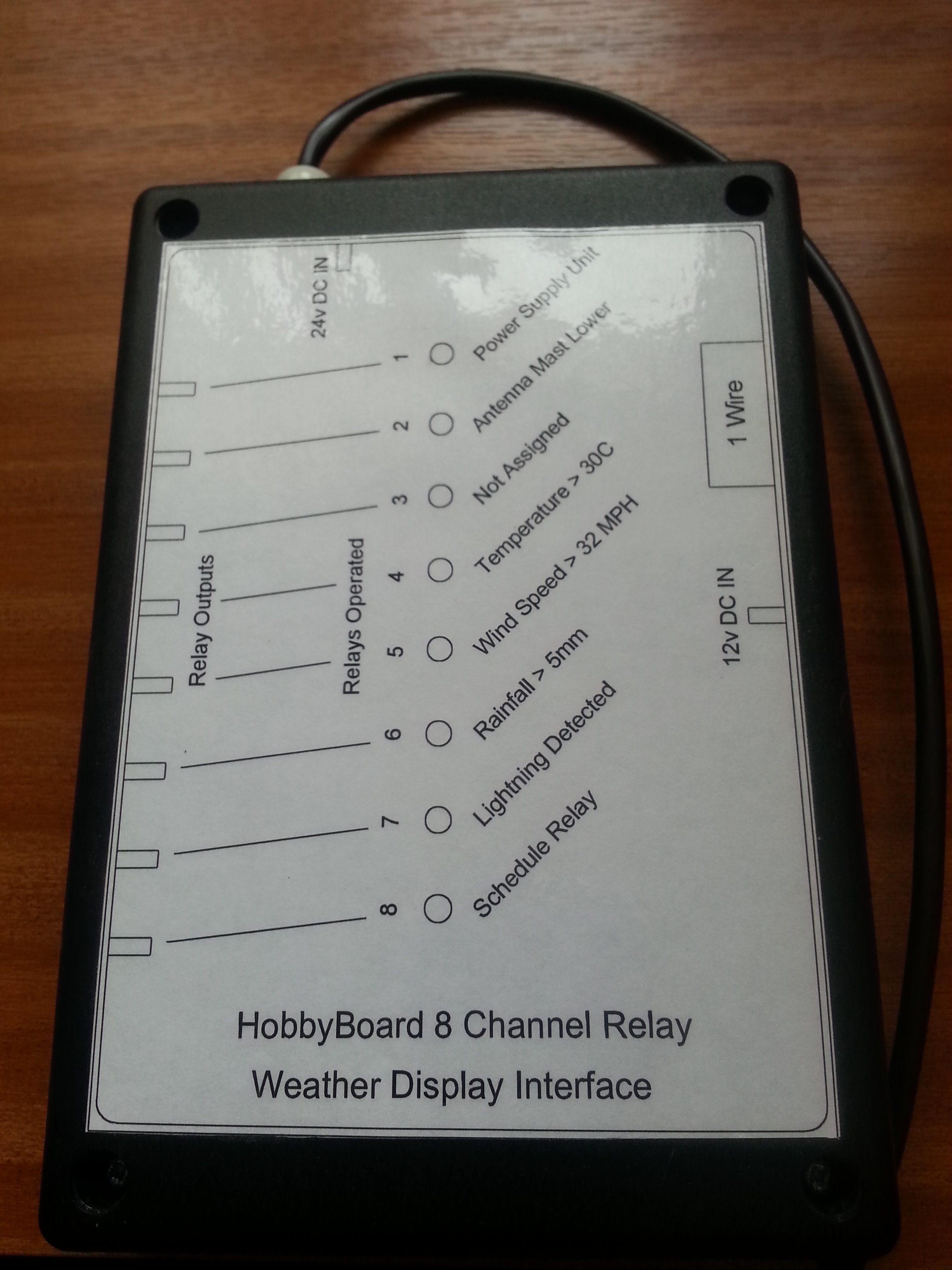
The weather station interface is a HobbyBoard 8 channel relay unit (unfortunately these are no longer available from HobbyBoard), this is linked to Weather Display software to control the output relays when certain pre-configured thresholds are met.
I have wired the internal relays in parallel so if any relay operates it will send a positive voltage to the PLC weather input (WX) which in turn will lower the mast if raised.
I have set the mast to lower should the wind speed exceed 30MPH and if 8 strikes of lightning within 1 minute are detected, these values may well change in future as experience grows.
The next stage is to mount the external enclosure on the wall and strip down the existing control circuit and replace it with the PLC control, this will mean adding new cables to the mast to pick up the additional proximity sensors and a multicore cable to the shack to the control box, the wireless handsets I currently use will then only be used as I’m luffing the mast.
Please see Part 3 HERE.