
Third installment of the thrilling journey to install automation control to raise and lower my 12m radio mast, Part 2 is HERE.
As it was such a lovely few days weather I thought I’d spend some time working on mast automation, the proximity sensors (link to sensor blog) have been installed previously, so it was time to wire them up.
I bought some 10mm convoluted tube and ‘Tee’ fittings from Hilltop Products, 3/8″ P clips came courtesy of eBay, the existing mast control wiring arrangement was completely removed and replaced with new tube and clips, an 8 core cable (Alarm cable 7/0.2mm) was drawn in, each of the four mast sensors had a unique signal cable, the other four cores were doubled up for 24v power to the sensors.
The ‘Tee’ pieces were ideal to close on the Superseal connector rubber boots and gives a great finish.
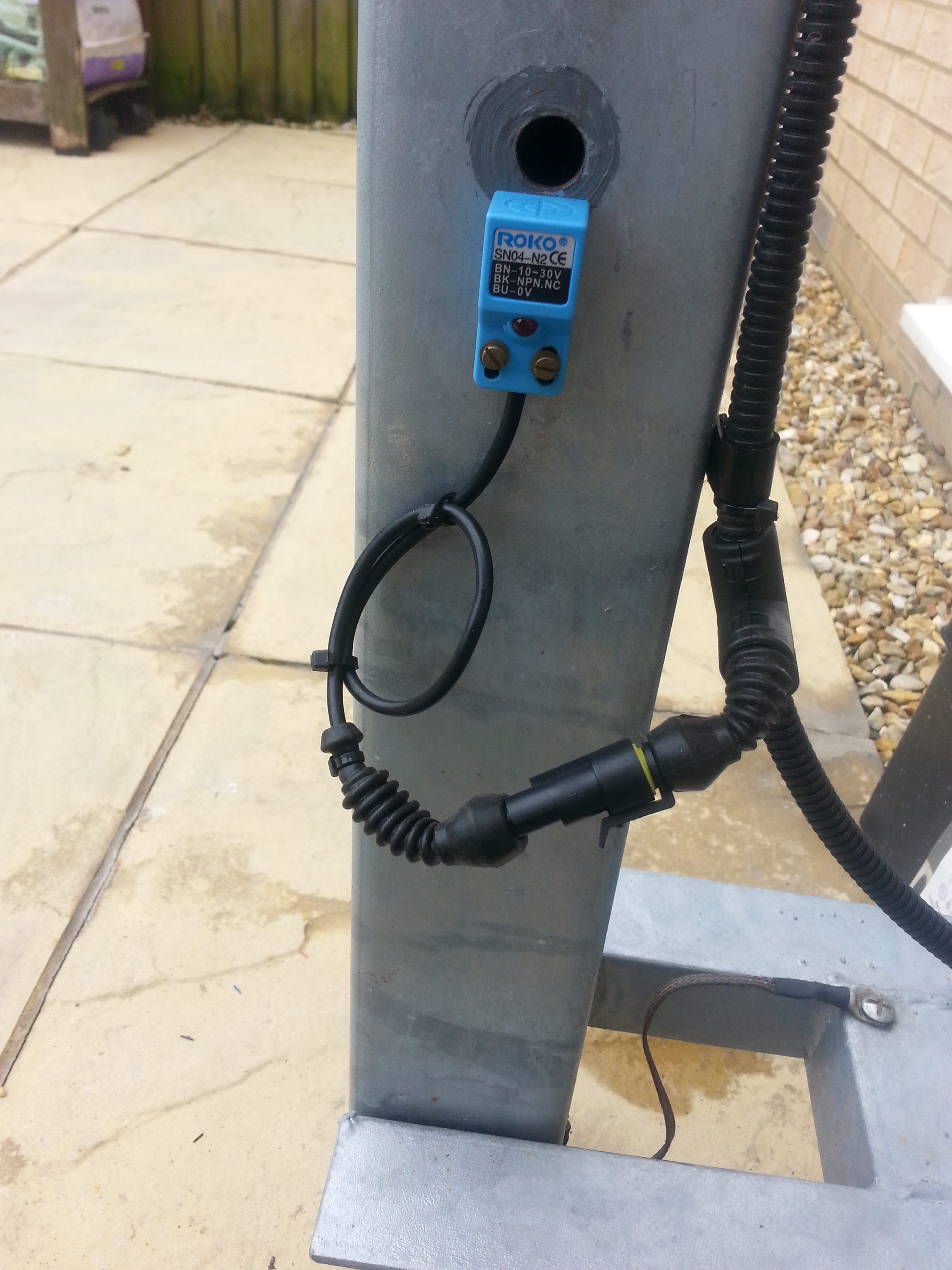
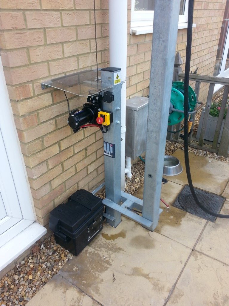
I fitted an Emergency Stop button to the side of the mast and added a longer length of cable to the solar panel via a Superseal connector, existing control relays in the battery box were also removed and enclosure holes sealed.
It was at the point of cleaning up the battery box that I measured the current draw taken by the high current relay when energized, I had factored about 1A, however it turned out to be 2.5A, this meant that my controllers wiring loom switching wires were underrated.
I had neatly lace wired with waxed cord my loom, and it took me ages to undo that good work and replace the switching wires with 0.75mm2 singles, one this was done, it was out with the waxed cord for round two.
The reason so much effort was taken with cable identification and looming was that all the kit had to be striped from the wooden backboard in order for the board to fit back in the enclosure, once in, the kit gets remounted, it’s not a big space to work so I knew I had to make it robust against wires coming out.
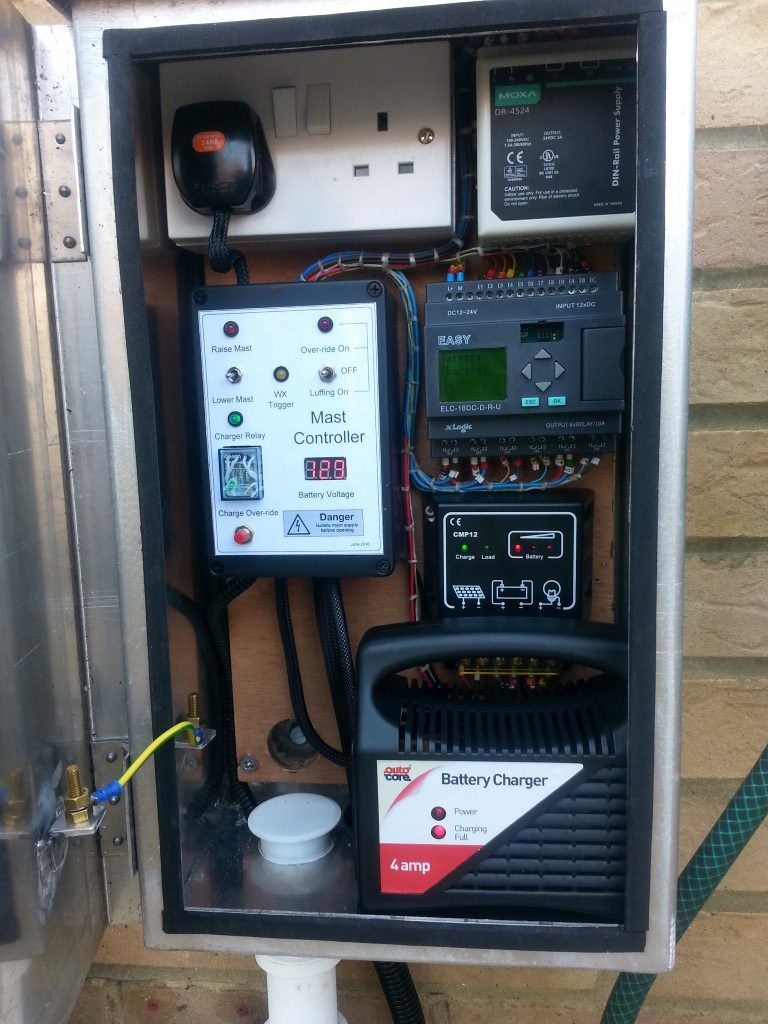
Once installed and powered up, I tested the speed of operation of the emergency stop button, fortunately its as near as instant as I could perceive, so I pressed and released the mast raise switch, and stood back with my hand on the E-Stop in case it overshot the limits and the run timer was set too long, as it was it work perfectly, as did the lowering operation, the picture was taken after I pressed the Battery Charge override button, this disconnects the battery from the solar panel charger as the 4A charge is ON, battery voltage is displayed on the Mast Controller box and when this reaches 14.14v, the PLC will turn the charging relay off, reconnecting the battery to the solar charger once more.
Every four lifts of the mast or every Sunday at 01:00 whichever is sooner will cause the charging sequence to begin, in case the battery is unable to reach the set-point voltage, the PLC will disconnect the charger after 10 hours of use.
The white pipe at the bottom of the enclosure is for a single 12 core to the remote control unit in the shack, this is the next job to wire.
Power to the motor is from a 45Ah 360A battery, the original 063 type from Halfords was beginning to signs of aging, so I bought the one below from eBay for £24:50 in January 17:
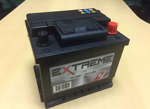
The battery is maintained by a solar panel and after 4 lifts, a 4A charger kicks in, solar panel charging currrent is 502mA: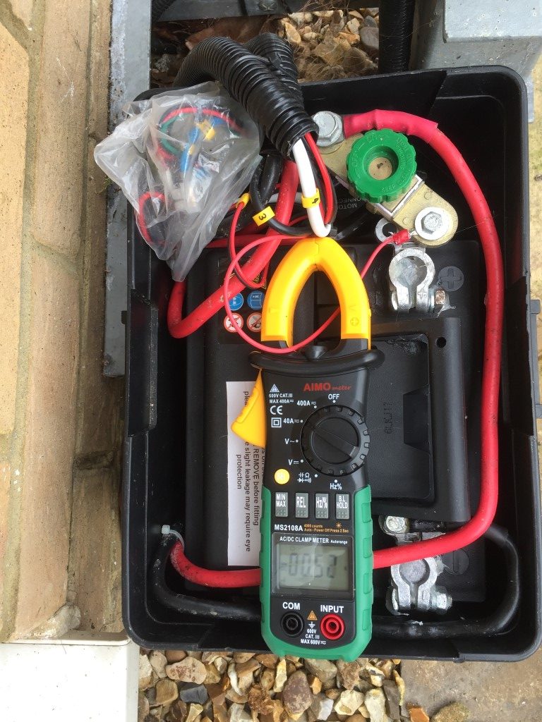
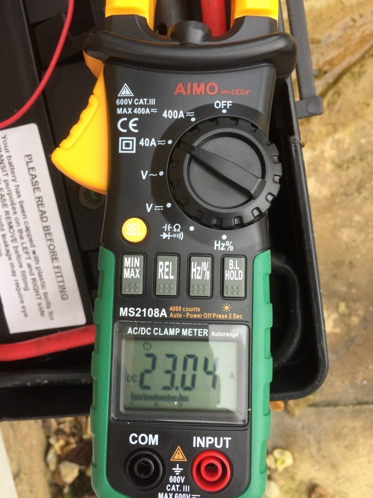
Current drawn by the motor raising the mast is a little over 23A, the duration is approximatly 47 seconds for the mast to reach full height.
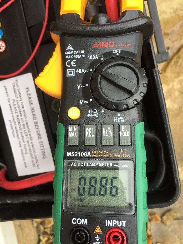
The Load and time taken to lower the mast is a lot lower at 8.86A.
Please see Part 4 HERE.