Updated 29 September 2023
Since my last blog on Mast Automation when I thought I’d finished the project, I have made some changes to my weather station which means I no longer have an output to the mast controller, this output used to trigger the mast to lower when the wind speed hits 30 mph.
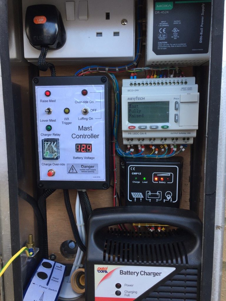
I decided to update the discontinued version of my Programmable Logic Controller (PLC) with a Rievtech PR-18DC-DA-R from Audon Ltd, this unit is a direct replacement for my old PLC and has 12 Inputs and 6 relay Outputs.
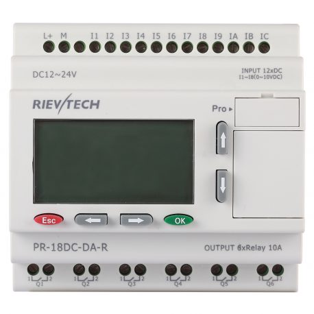
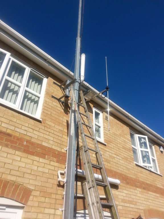
The PLC accepts a number of input types, in my application I’m simply switching a voltage state with the exception of one of the inputs which is configured as an Analogue input, to which I have connected my mast mounted Anemometer (https://www.mouser.co.uk/ProductDetail/485-1733?R=1733virtualkey54950000virtualkey485-1733) as a means to trigger mast lowering during unsafe wind conditions.
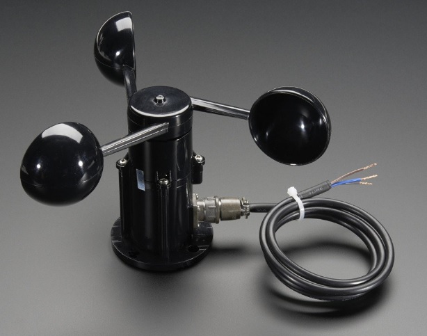
Adafruit 1733
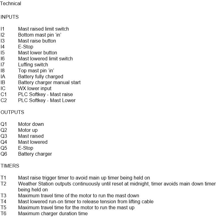
TECHNICAL DETAILS
- Height (base to center): 105mm / 4.1″
- Center out to Cup: 102mm / 4″
- Arm Length: 70mm / 2.8″
- Weight: 111.8g
Wire Dimensions:
- Wire Length: 99cm / 39″
- Plug Length: 30mm / 1.2″
- Diameter (thickness): 4.8mm / 0.2″
Specifications
- Output: 0.4V to 2V
- Testing Range: 0.5m/s to 50m/s (111.8 mph)
- Start wind speed: 0.2 m/s
- Resolution: 0.1m/s
- Accuracy: Worst case 1 meter/s
- Max Wind Speed: 70m/s (156.5 mph)
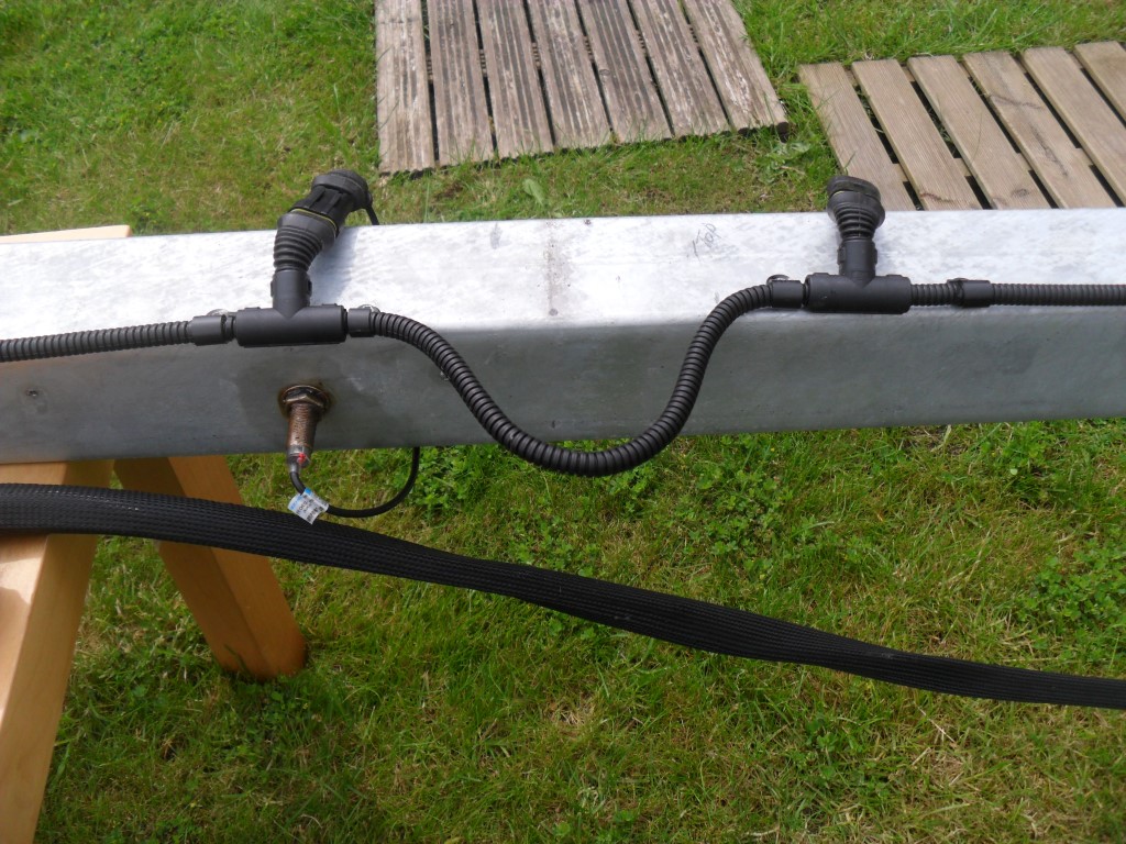
- Connector details: Pin 1 – Power (brown wire), Pin 2 – Ground (black wire), Pin 3 – Signal (blue wire), Pin 4 not connected
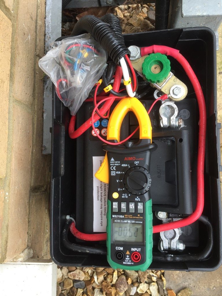
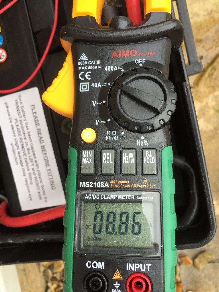
I tested the output with help from my better half by driving at steady speed and monitoring the output from the anemometer:
- 0 mph = 0.40 mV
- 25 mph = 0.75 – 79 mV
- 30 mph = 80 mV
- 31 mph = 81 – 88 mV
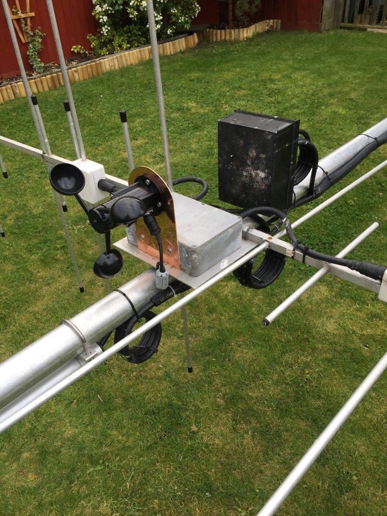
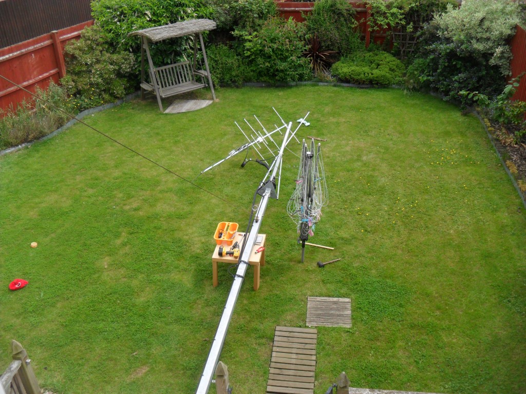
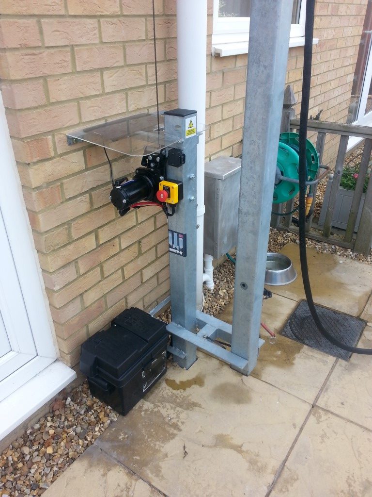
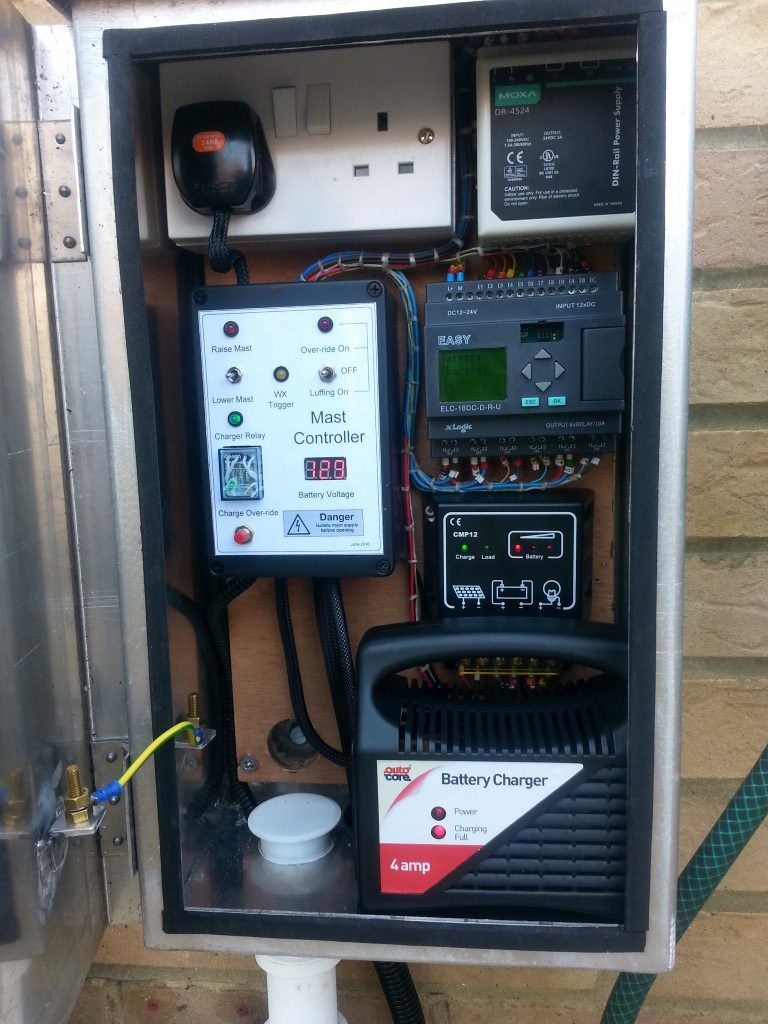
I mounted the anemometer to the top of my mast to get a representative wind speed, the next job was to strip out the old PLC from the control cabinet.
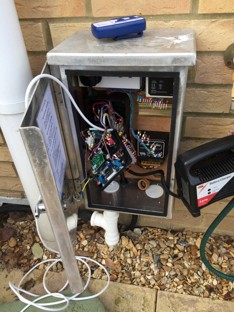
I needed to make several changes from the original design in order to free up one of the PLC’s inputs, also out of the 16 Inputs only the first 6 allow analogue inputs, so some moving of inputs was needed along with some minor works to the LED voltages and override/luffing switch.
All went back together quite nicely but an intermittent problem remained after the PLC replacement in that when the mast completed the mast raise cycle, the motor would immediately reverse and the mast would lower.
Hooking up the laptop to to the PLC, I selected ‘live monitoring’, this displayed the input and output condition, this showed that after operating the ‘raise’ toggle switch (centre bias On – Off – On centre off), the ‘lower’ switch input also went and remained high. This output to the PLC caused the motor to immediately change direction and lower the moment the mast raised sensor was triggered.
To reduce the chance of a repeat problem occurring, I modified the replacement DPDT switch wiring so that both poles need to switch in order for a signal to pass.

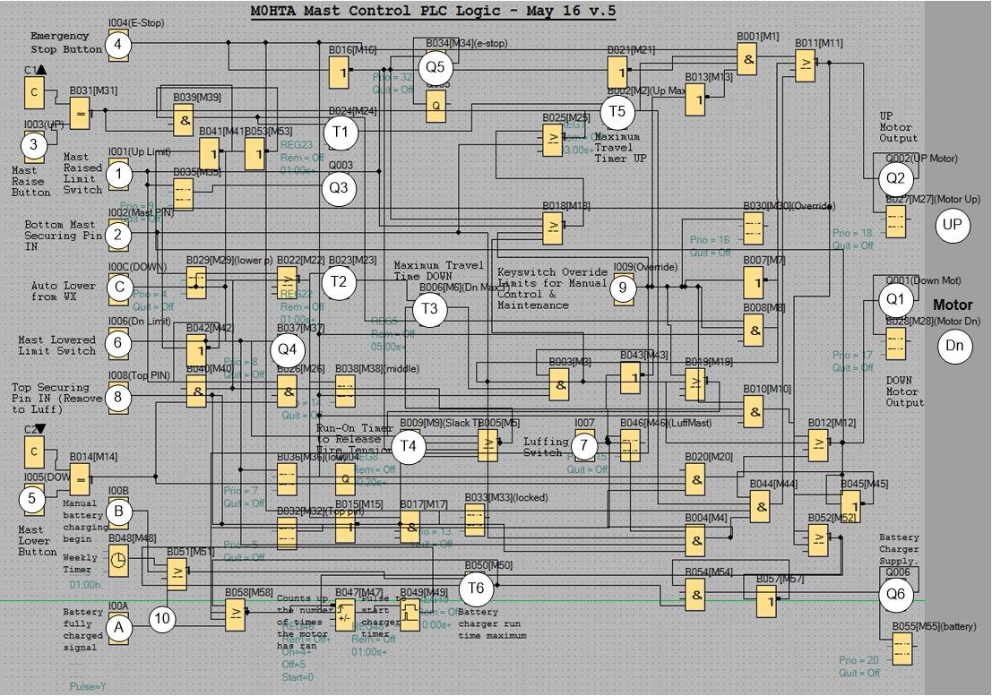
Prior to starting the upgrade works I had the programmed PLC on the bench and I thoroughly tested all control permutations by simulation using the software from Audon Ltd to ensure correct operation.
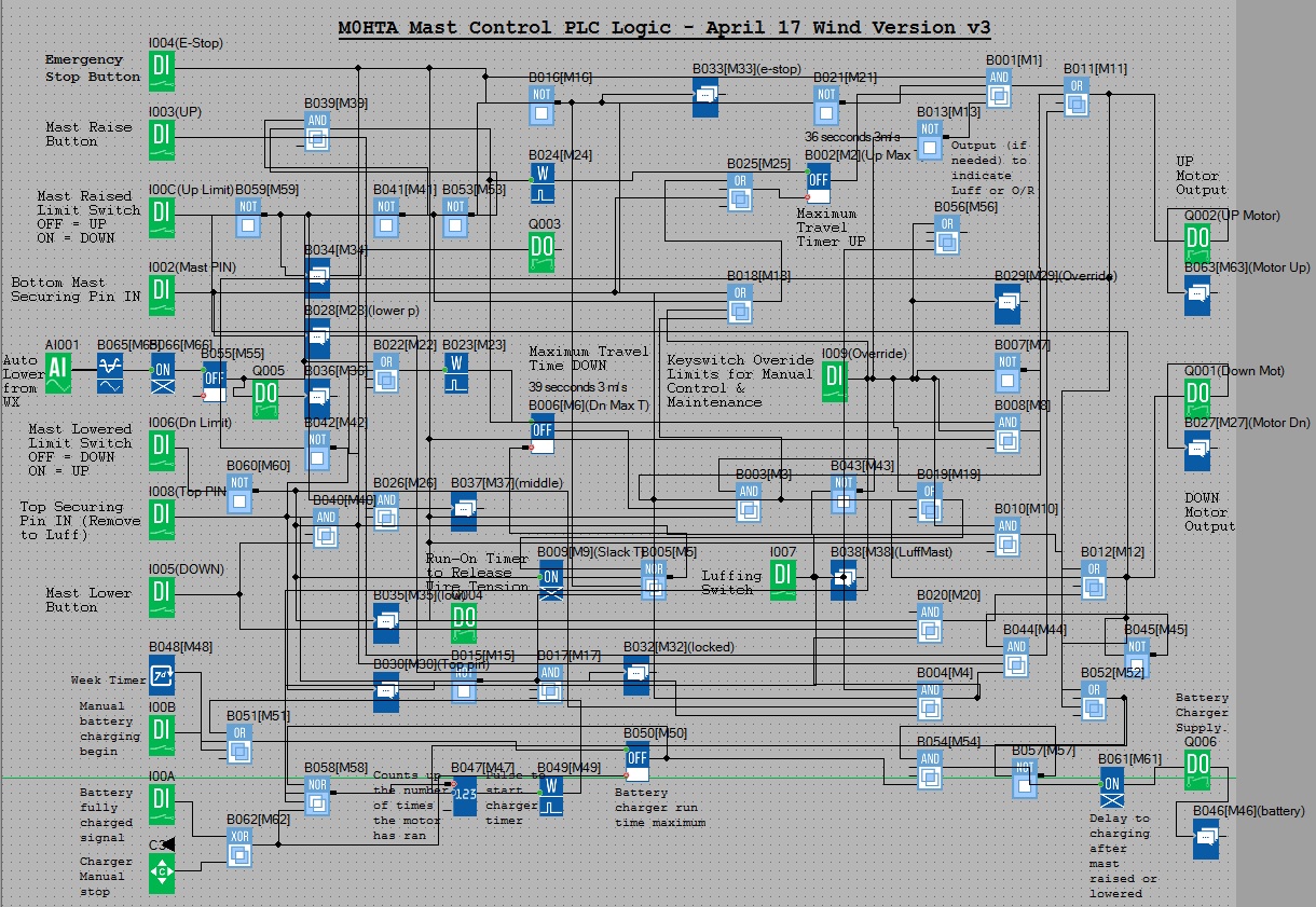
As you can see, the logic has grown with the project, I’m sure this could be significantly simplified, however, it works for me.
Mast Control Logic
Pressing the Emergency Stop button will inhibit any operation and reset any timers which are running, also a message is displayed ‘*warning* E-STOP operated’
Raising the Mast
Conditions –
- E Stop not pressed. (Input 1004).
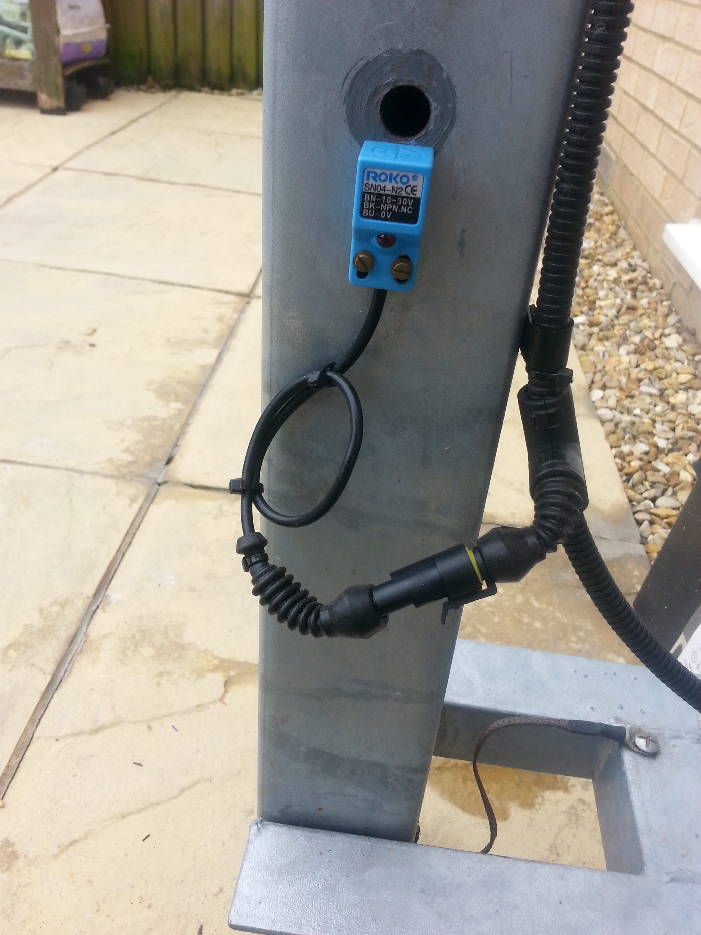
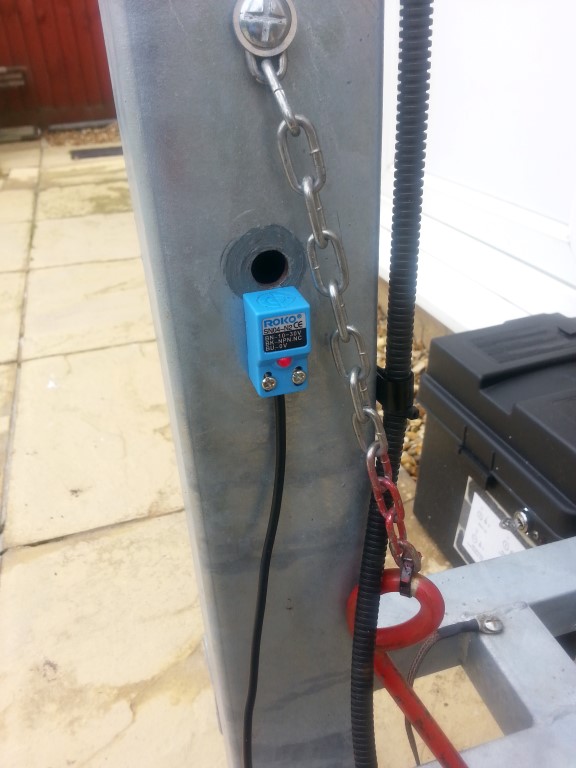
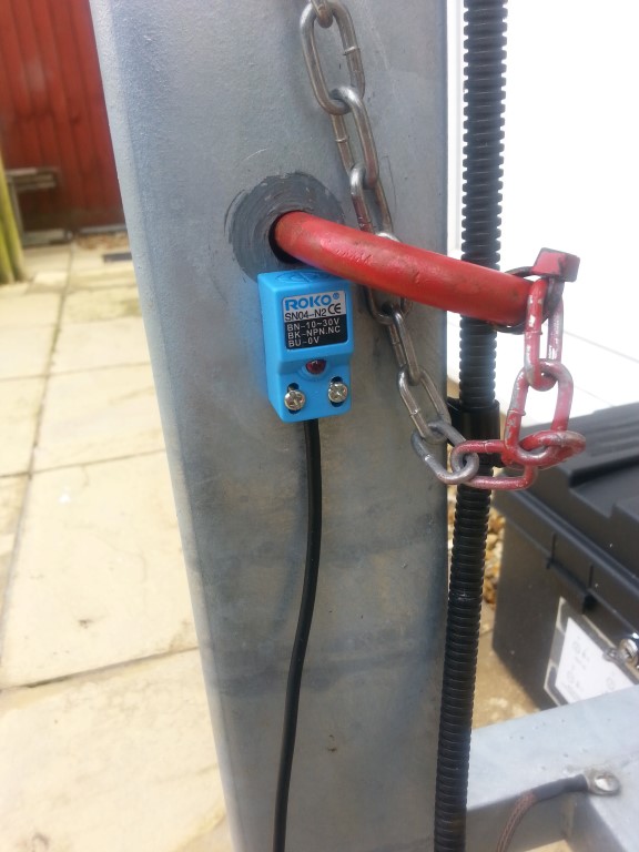
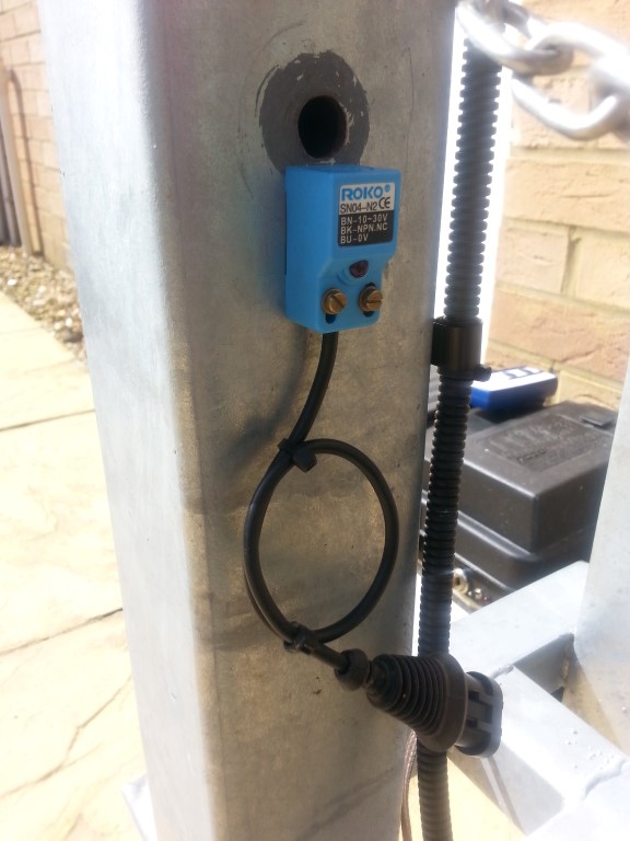
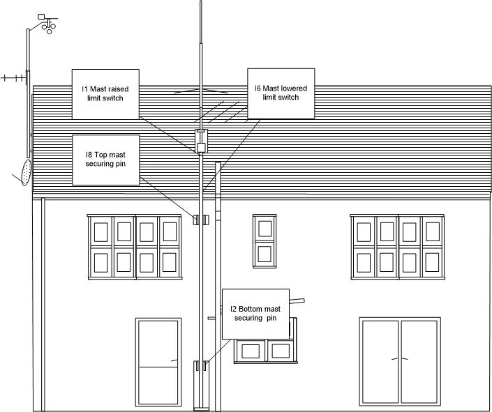
- Top Securing mast pin IN. (Input 1008).
- Mast in the lowered position. (Input 1006).
Trigger – Switch input momentary high. (Input 1003).
Action –
- Lower switch inhibited.
- Switch input via wiping relay with a 1 second ON timer to ensure momentary trigger to the next stage.
- 36 second up timer start to operate Up relay (fail mechanism in case the ‘raised’ sensor fails).
- Up relay closes to energize motor drive. (Q002).
- After expiry of Up timer or on activation of the Up sensor, Up relay opens.
- Mast raised output relay energizes. (Q003).
- Message displayed ‘up motor running’ then ‘mast fully raised’.
Lowering the Mast
Conditions –
- E Stop not pressed. (Input 1004).
- Top Securing mast pin IN. (Input 1008).
- Mast in the raised position. (Input 100C).
Trigger – Switch input momentary high. (Input 1005).
Action –
- Raise switch inhibited.
- Switch input via wiping relay with a 1 second ON timer to ensure momentary trigger to the next stage.
- 39 second down timer starts to operate Down relay (fail mechanism in case the ‘lowered’ sensor fails).
- Down relay closes to energize motor drive. (Q001).
- After expiry of Down timer or on activation of the Down sensor, run on timer operates for 0.15 seconds to take slack off winch cable.
- After expiry of run-on timer, Down relay opens.
- Mast lowered output relay energizes. (Q004).
- Message displayed ‘down motor running’ then ‘mast fully lowered’.
Wind Speed Triggered Auto Lower
Conditions –
- E Stop not pressed. (Input 1004).
- Top Securing mast pin IN. (Input 1008).
- Mast in the raised position. (Input 100C).
Trigger – Wind measured via Anemometer at 28 mph for 15 seconds. (Input A1001).
Action –
- 0.4 – 2v Anemometer to Analogue Threshold Trigger output set go high at 80 mV and off at 76mV, these values equate to ~28 mph and ~24 mph respectively.
- ‘On Delay’ timer from analogue threshold trigger set for a sustained output of 15 seconds duration before the next stage is enabled in order to reject gusts.
- ‘Off Delay’ timer set to 10 minutes, if no input from the ‘On Delay’, ‘Off Delay’ resets.
- Whilst the ‘Off Delay’ timer is running, the WX Amber LED is lit. (Q005).
- Output from ‘Off Delay’ to wiping relay timer set to 1 second to ensure a momentary output to the next stage.
- 39 second down timer starts to operate Down relay (fail mechanism in case ‘lowered’ sensor fails).
- Down relay closes to energize motor drive. (Q001).
- After expiry of Down timer or on activation of the Down sensor, run on timer operates for 0.15 seconds to take slack off winch cable.
- After expiry of run-on timer, Down relay opens.
- Mast lowered output relay energizes. (Q004).
- Message displayed ‘high wind trigger auto-lower active’.
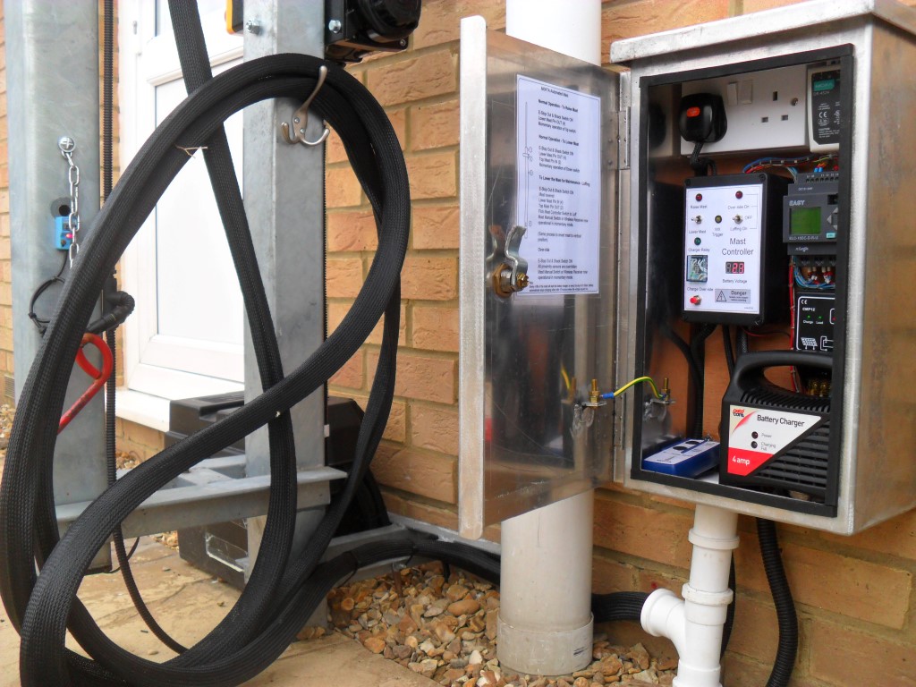
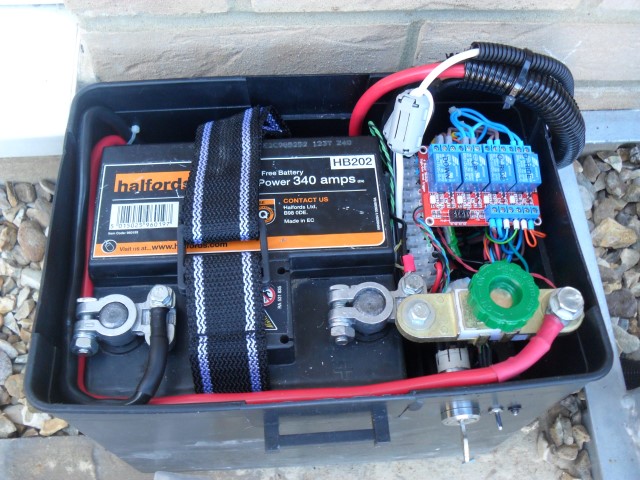
Battery Charging Process
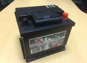
The winch has 3000lb capacity from Winch-It and is powered by a 12v car battery with a capacity of 45Ah – 360cca.
Normal Operation – 25w solar panel connected to the battery via CMP Solar Charge Controller.
Automatic Operation –
Trigger – After 4 operations of the motors (raise & lower twice) or Weekly – Sunday 01.00.
Action –
- Multi-pole relay energizes after a 2 second delay via Q006, this:
- Disconnects the solar panel.
- Applies mains to a 4A output battery charger (charger sized for Ah of battery).
- Connects the battery charger output to the battery.
- Message displayed ‘battery charging’.
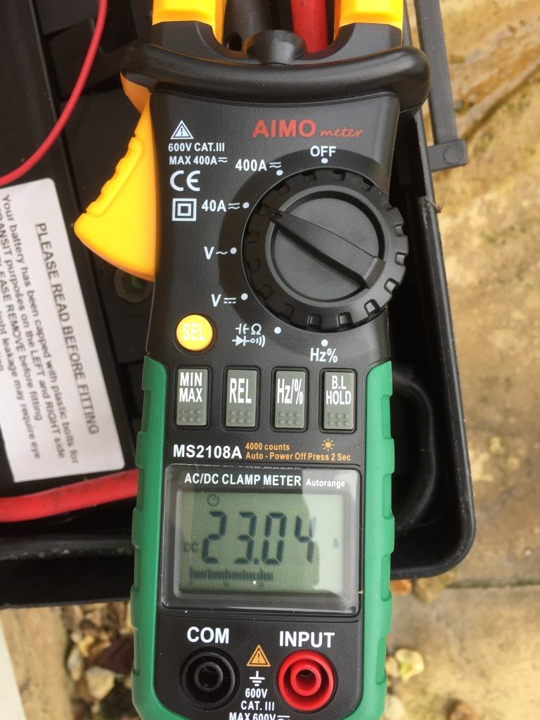
Charging ceases when:
- Battery terminal voltage reaches 14.14v (Over-voltage detection module to Input 100A).
- 8-hour battery run timer expires.
Manual Operation –
Charging Start – Push button in control cabinet (Input 100B).
Charging Stop – Cursor key on PLC (C3).
Notes-
- If the battery charging cycle has started and the motor (either up or down) is operated, charging will cease and resume after a delay of 2 seconds after the motor has stopped.
- Up-Counter resets to zero when the charger is ON.
Luffing the Mast
Conditions –
- E Stop not pressed. (Input 1004).
- Top Securing mast pin Out. (Input 1008).
- Bottom Securing mast pin In (Input 1002).
- Mast in the lowered position. (Input 1006).
- Luffing switch set to On (Input 1007).
Trigger – Momentary switch (raise or lower) (Inputs 1003 or 1005).
Action – Operating the Luffing switch supplies power to the wireless receiver and manual switch which came with the Winch-It kit via a relay , the supply for this is taken from the Luffing/Override indicator LED, (the Luffing switch is a Double Pole Double Throw On – Off – On, the LED is fed from one side of the switch).
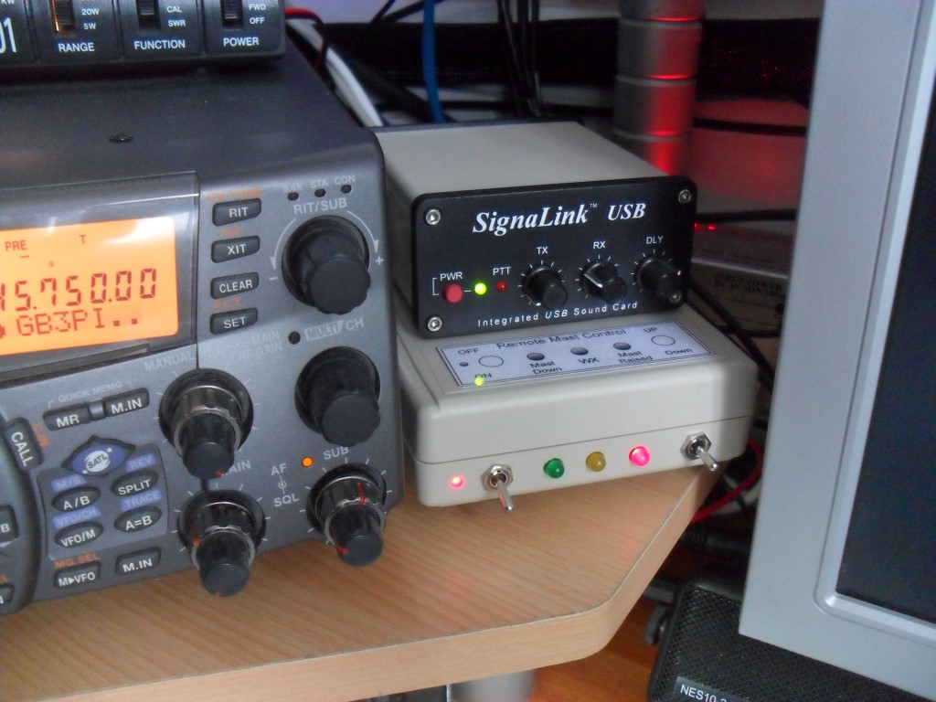
A further change to the control is to from latching to momentary switch operation allowing the motor to be ‘inched’ via the wireless handset or panel switches in the control cabinet.
Using the handset allows the mast to be walked down whilst lowering or the reverse when reinstating the mast to the vertical.
Message displayed ‘mast switched to luff’.
Override
Operating the Override switch bypass all limit switches and enables momentary manual control.
Message displayed ‘ override switch on’.
Other Alert/Warning Messages
Top pin in, message displayed ‘top mast securing pin in’.
Bottom pin in, displayed message ‘bottom securing pin in’.
Both top and bottom pins in, message displayed ‘both mast securing pins in’.
Update
After breaking the winch cable and managing to replace it, (see HERE), I’ve added motor overcurrent detection to halt any process which is taking too much power.