After playing with a Programmable Logic Controller (PLC) to operate my radio mast, I decided to build a simulator in order to better understand the capabilities of the EASY PR-18DC-DA-R.
I wanted the simulator to have 16 inputs, either momentary or switched and the ability to import signals including an embedded 4 – 20mA current.
I had a sloped project enclosure already, so I made a dimensioned drilling template.
Once the template was stuck down, the pilot holes were drilled, template removed and holes opened to the right sizes.
The template was created in Visio and I used layers, one of the layers was for switch position drilling and alignment cross-hairs, turning that layer off (missed one in I8!), allowed me to print on self-adhesive sticky Matte White Vinyl.
Using a sharp knife, I cut though the Vinyl and started fitting the switches, buttons, Output indication LEDs and 4 – 20mA injector.
Terminal posts next.
Front panel populated.
Wiring started.
After a couple of changes, the internal wiring is completed and loomed in.
The simulator uses 24v DC, I used a small 1.5A output switched mode PSU for this, fed via a chassis fuse holder with the supply from an IEC male socket, the output from the PSU is fused separately.
PLC simulator all powered up, the program in the PLC was legacy from my mast control project, this will be overwritten by downloading revised programs from xLogicsoft software.
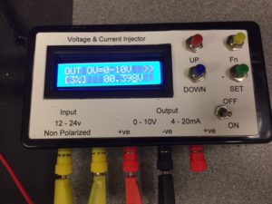
To complement the PLC simulator I bought a4-20mA Current Signal Generator 0-10V Voltage Generator Transducer Simulator for £19.00.
Since my last blog on Mast Automation when I thought I’d finished the project, I have made some changes to my weather station which means I no longer have an output to the mast controller, this output used to trigger the mast to lower when the wind speed hits 30 mph.
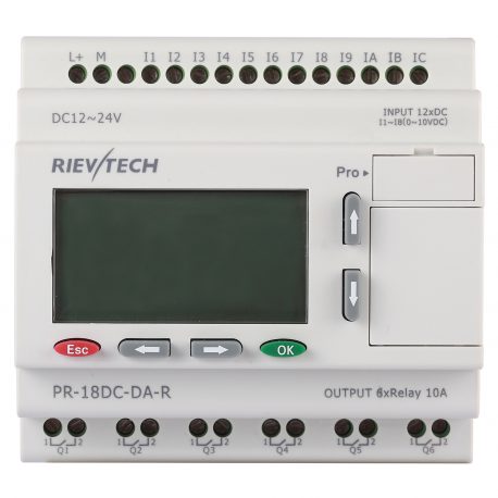
I decided to update the discontinued version of my Programmable Logic Controller (PLC) with a Rievtech PR-18DC-DA-R from Audon Ltd, this unit is a direct replacement for my old PLC and has 12 Inputs and 6 relay Outputs.
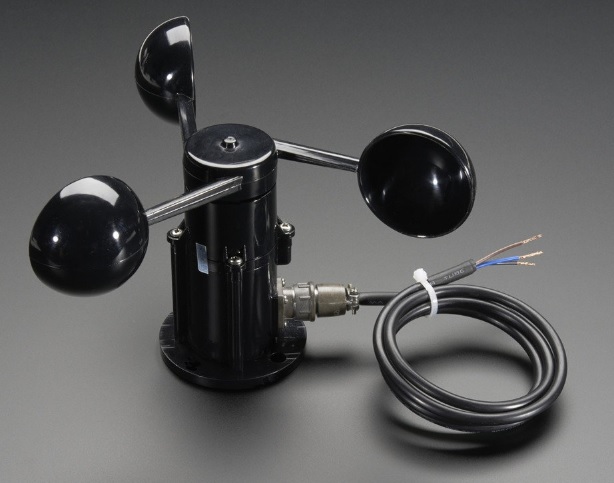
The PLC accepts a number of input types, in my application I’m simply switching a voltage state with the exception of one of the inputs which is configured as an Analogue input, to which I have connected my mast mounted Anemometer (https://www.mouser.co.uk/ProductDetail/485-1733?R=1733virtualkey54950000virtualkey485-1733) as a means to trigger mast lowering during unsafe wind conditions.
Adafruit 1733
TECHNICAL DETAILS
Dimensions:
Height (base to center): 105mm / 4.1″
Center out to Cup: 102mm / 4″
Arm Length: 70mm / 2.8″
Weight: 111.8g
Wire Dimensions:
Wire Length: 99cm / 39″
Plug Length: 30mm / 1.2″
Diameter (thickness): 4.8mm / 0.2″
Specifications
Output: 0.4V to 2V
Testing Range: 0.5m/s to 50m/s (111.8 mph)
Start wind speed: 0.2 m/s
Resolution: 0.1m/s
Accuracy: Worst case 1 meter/s
Max Wind Speed: 70m/s (156.5 mph)
Connector details: Pin 1 – Power (brown wire), Pin 2 – Ground (black wire), Pin 3 – Signal (blue wire), Pin 4 not connected
I tested the output with help from my better half by driving at steady speed and monitoring the output from the anemometer:
0 mph = 0.40 mV
25 mph = 0.75 – 79 mV
30 mph = 80 mV
31 mph = 81 – 88 mV
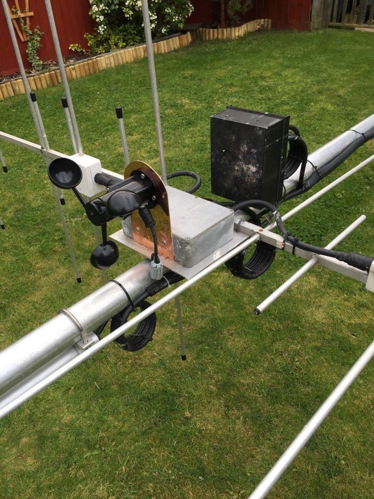
Anemometer mounted on 2m/70cm H/V relay switch box
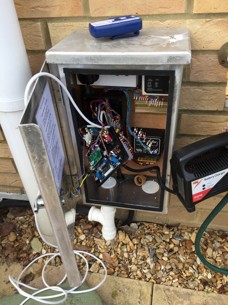
I mounted the anemometer to the top of my mast to get a representative wind speed, the next job was to strip out the old PLC from the control cabinet.
Starting mods, (hand held winch controller on top of cabinet)
I needed to make several changes from the original design in order to free up one of the PLC’s inputs, also out of the 16 Inputs only the first 6 allow analogue inputs, so some moving of inputs was needed along with some minor works to the LED voltages and override/luffing switch.
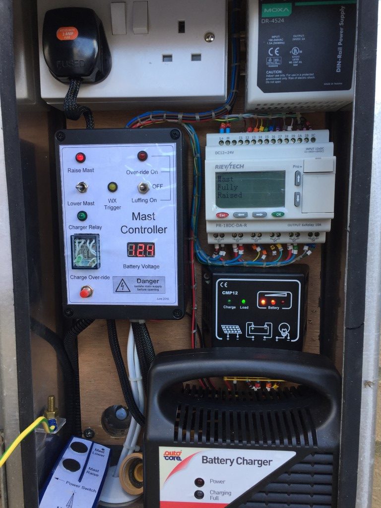
Completed Cabinet
All went back together quite nicely but an intermittent problem remained after the PLC replacement in that when the mast completed the mast raise cycle, the motor would immediately reverse and the mast would lower.
Hooking up the laptop to to the PLC, I selected ‘live monitoring’, this displayed the input and output condition, this showed that after operating the ‘raise’ toggle switch (centre bias On – Off – On centre off), the ‘lower’ switch input also went and remained high. This output to the PLC caused the motor to immediately change direction and lower the moment the mast raised sensor was triggered.
To reduce the chance of a repeat problem occurring, I modified the replacement DPDT switch wiring so that both poles need to switch in order for a signal to pass.
Prior to starting the upgrade works I had the programmed PLC on the bench and I thoroughly tested all control permutations by simulation using the software from Audon Ltd to ensure correct operation.
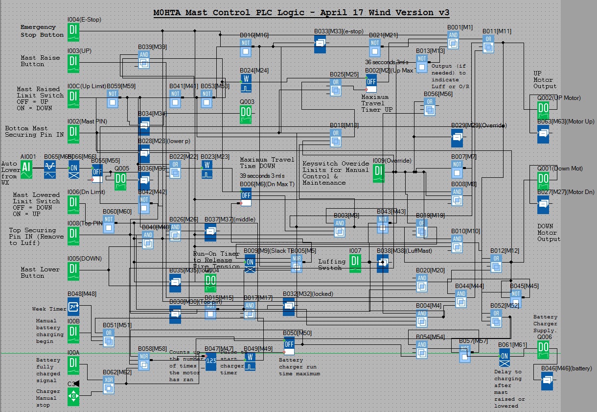
PLC Modified block diagram (Program File for use with xLogicsoft)
As you can see, the logic has grown with the project, I’m sure this could be significantly simplified, however, it works for me.
Mast Control Logic
Pressing the Emergency Stop button will inhibit any operation and reset any timers which are running, also a message is displayed ‘*warning* E-STOP operated’
Switch input via wiping relay with a 1 second ON timer to ensure momentary trigger to the next stage.
39 second down timer starts to operate Down relay (fail mechanism in case the ‘lowered’ sensor fails).
Down relay closes to energize motor drive. (Q001).
After expiry of Down timer or on activation of the Down sensor, run on timer operates for 0.15 seconds to take slack off winch cable.
After expiry of run-on timer, Down relay opens.
Mast lowered output relay energizes. (Q004).
Message displayed ‘down motor running’ then ‘mast fully lowered’.
Wind Speed Triggered Auto Lower
Conditions –
E Stop not pressed. (Input 1004).
Top Securing mast pin IN. (Input 1008).
Mast in the raised position. (Input 100C).
Trigger – Wind measured via Anemometer at 28 mph for 15 seconds. (Input A1001).
Action –
0.4 – 2v Anemometer to Analogue Threshold Trigger output set go high at 80 mV and off at 76mV, these values equate to ~28 mph and ~24 mph respectively.
‘On Delay’ timer from analogue threshold trigger set for a sustained output of 15 seconds duration before the next stage is enabled in order to reject gusts.
‘Off Delay’ timer set to 10 minutes, if no input from the ‘On Delay’, ‘Off Delay’ resets.
Whilst the ‘Off Delay’ timer is running, the WX Amber LED is lit. (Q005).
Output from ‘Off Delay’ to wiping relay timer set to 1 second to ensure a momentary output to the next stage.
39 second down timer starts to operate Down relay (fail mechanism in case ‘lowered’ sensor fails).
Down relay closes to energize motor drive. (Q001).
After expiry of Down timer or on activation of the Down sensor, run on timer operates for 0.15 seconds to take slack off winch cable.
Amber LED indicating high wind has triggered lowering the mast and inhibiting it from raising whilst lit.
Battery Charging Process
The winch has 3000lb capacity from Winch-It and is powered by a 12v car battery with a capacity of 45Ah – 360cca.
Normal Operation – 25w solar panel connected to the battery via CMP Solar Charge Controller.
Automatic Operation –
Trigger – After 4 operations of the motors (raise & lower twice) or Weekly – Sunday 01.00.
Action –
Multi-pole relay energizes after a 2 second delay via Q006, this:
Disconnects the solar panel.
Applies mains to a 4A output battery charger (charger sized for Ah of battery).
Connects the battery charger output to the battery.
Message displayed ‘battery charging’.
Charging ceases when:
Battery terminal voltage reaches 14.14v (Over-voltage detection module to Input 100A).
8-hour battery run timer expires.
Manual Operation –
Charging Start – Push button in control cabinet (Input 100B).
Charging Stop – Cursor key on PLC (C3).
Notes-
If the battery charging cycle has started and the motor (either up or down) is operated, charging will cease and resume after a delay of 2 seconds after the motor has stopped.
Up-Counter resets to zero when the charger is ON.
Luffing the Mast
Conditions –
E Stop not pressed. (Input 1004).
Top Securing mast pin Out. (Input 1008).
Bottom Securing mast pin In (Input 1002).
Mast in the lowered position. (Input 1006).
Luffing switch set to On (Input 1007).
Trigger – Momentary switch (raise or lower) (Inputs 1003 or 1005).
Action – Operating the Luffing switch supplies power to the wireless receiver and manual switch which came with the Winch-It kit via a relay , the supply for this is taken from the Luffing/Override indicator LED, (the Luffing switch is a Double Pole Double Throw On – Off – On, the LED is fed from one side of the switch).
A further change to the control is to from latching to momentary switch operation allowing the motor to be ‘inched’ via the wireless handset or panel switches in the control cabinet.
Using the handset allows the mast to be walked down whilst lowering or the reverse when reinstating the mast to the vertical.
Message displayed ‘mast switched to luff’.
Override
Operating the Override switch bypass all limit switches and enables momentary manual control.
Message displayed ‘ override switch on’.
Other Alert/Warning Messages
Top pin in, message displayed ‘top mast securing pin in’.
Bottom pin in, displayed message ‘bottom securing pin in’.
Both top and bottom pins in, message displayed ‘both mast securing pins in’.
Update
After breaking the winch cable and managing to replace it, (see HERE), I’ve added motor overcurrent detection to halt any process which is taking too much power.
Continuing on with the radio mast automation, this blog shows how I have wired the controller. (Part 1 is HERE)
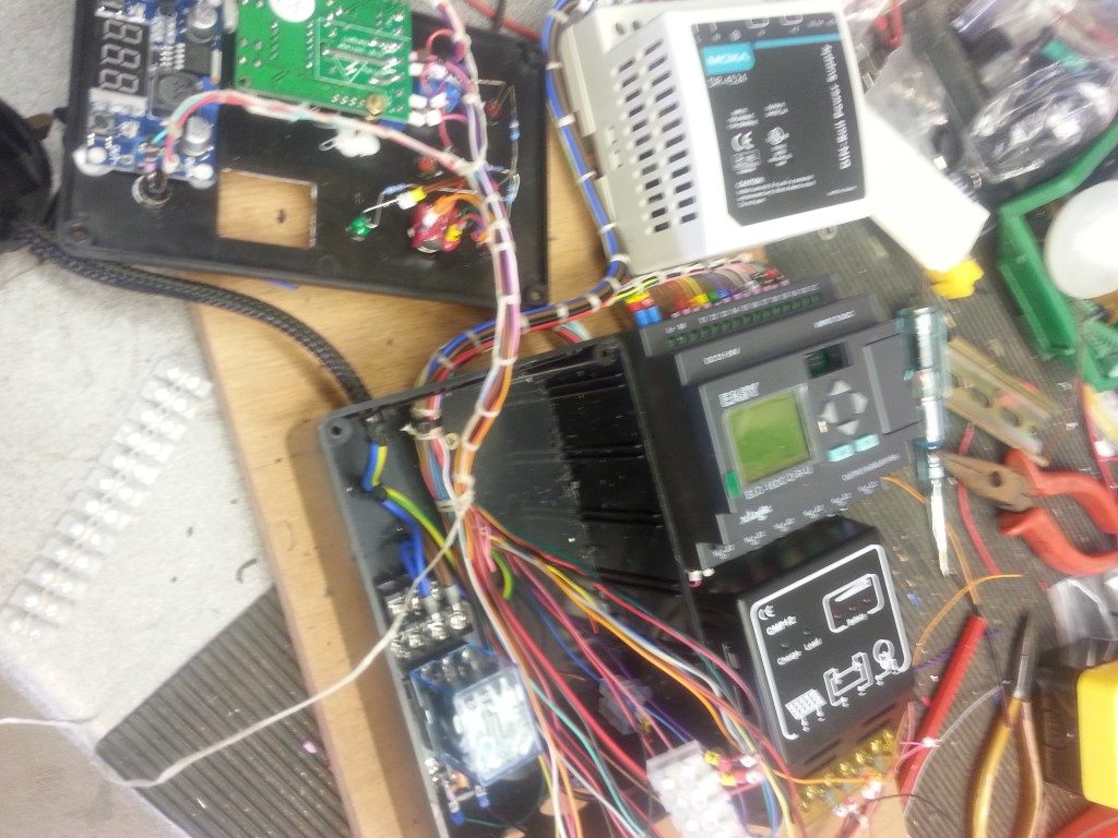
The external enclosure for the automation equipment has a plywood back board which is removable, it is to this I have mounted all the necessary bits of kit, I have loomed all the cables in with waxed lacing cord and given each conductor a unique ident for ease of fault finding.
To allow the back board to fit back into the enclosure I will have to strip everything of the board first, the 24v DC transformer and PLC are mounted on ‘top hat’ rail for ease of removal, the solar charge limiter and main control unit are held in place with wood screws.
The PLC controller is powered using 24v DC, I did try it on 12v but the output relays seemed sluggish when activated, the proximity sensors I’m using have a wide operating voltage range (9v – 30v) so these will be fed at 24v, due to the wide voltage tolerance, voltage drop will not be an issue considering the maximum cable run is 7 metres, (I’m using 8 core 7/0.2mm CSA).
The input to the PLC will be a switched high of 24v with the exception of the battery fully charged input (the board for this is affixed to the lid of the enclosure), when a charging voltage of 14.14v is reached, this will switch the battery voltage to the PLC input via a relay to cancel mains powered battery charging (link to blog on voltage relay HERE).
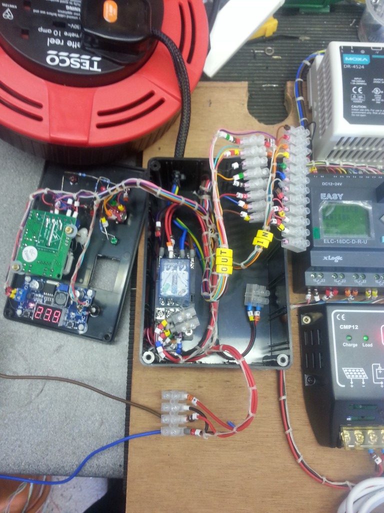
All cables have been marked up to aid fault finding or making additions to the control system should I need it, the image shows cables marked and ready for looming.
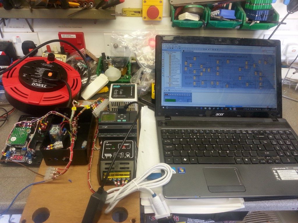
Cables loomed up with waxed lacing cord and powered up ready for bench testing.
Slight tweak to the PLC program to invert the Hall Effect limit switches, for testing purposes the run on timers were set at 5 seconds, after timing the raising and lowering of the mast with a fully charged battery, the correct timings have now been uploaded.
Phew!, the lid fits on the controller 🙂 and everything seems to work!
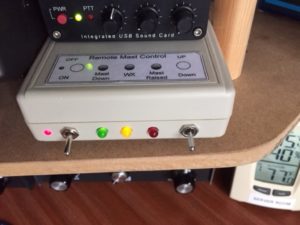
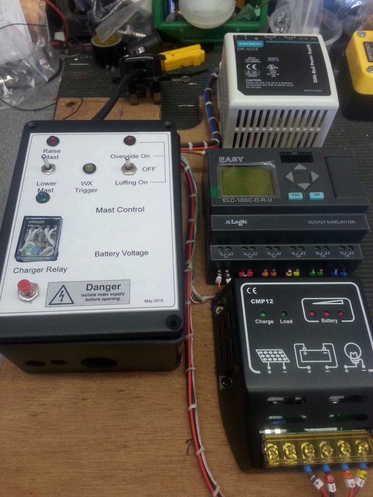
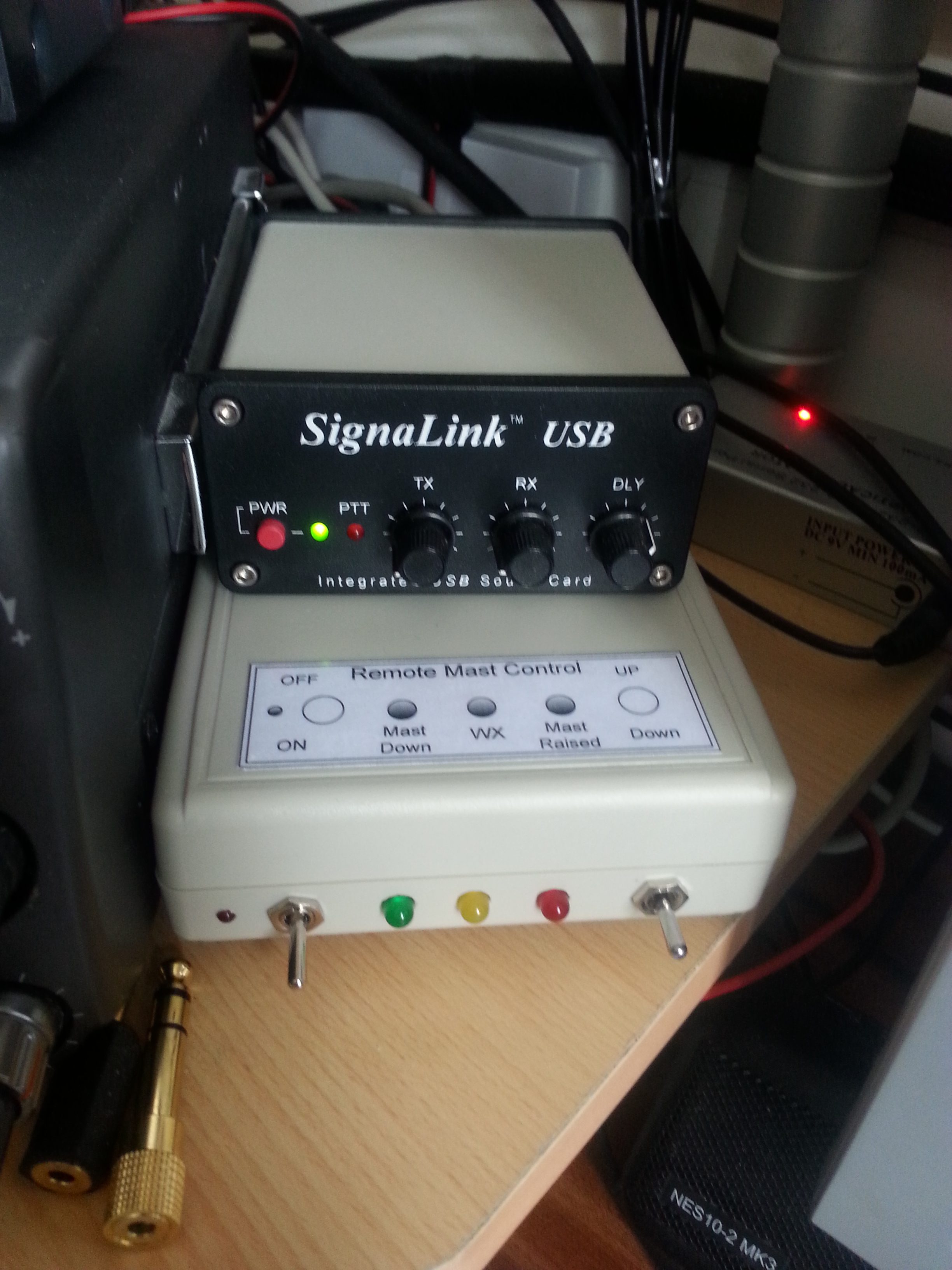
30 May 16 – I decided to use the enclosure which houses my Easy Rotor Control as the place to fit the indicators and remote switches to control the mast from the shack as it had plenty of room.
From Left to Right – The main On/Off switch is the first switch, in the ON position a small LED to the left of the switch will be lit, turning the switch OFF acts an Emergency Stop to the PLC
The Green LED is for mast fully lowered, the Amber LED is lit when an output from the weather station is active (next picture) and the Red LED is for mast fully raised, the switch on the right is momentary operation, non latching center off and is used to send a positive input to the PLC to either lift or lower the mast if the correct logic is satisfied.
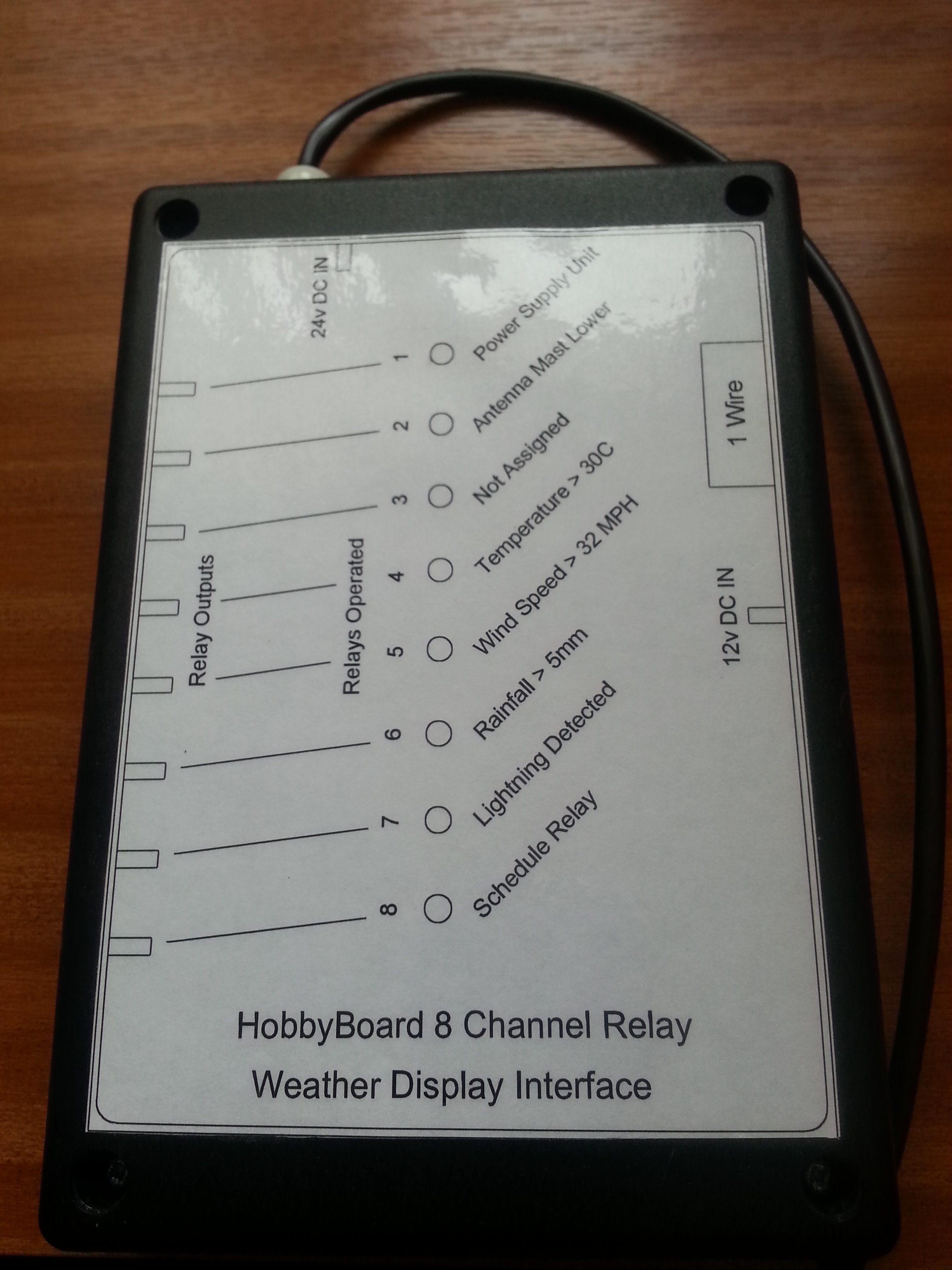
The weather station interface is a HobbyBoard 8 channel relay unit (unfortunately these are no longer available from HobbyBoard), this is linked to Weather Display software to control the output relays when certain pre-configured thresholds are met.
I have wired the internal relays in parallel so if any relay operates it will send a positive voltage to the PLC weather input (WX) which in turn will lower the mast if raised.
I have set the mast to lower should the wind speed exceed 30MPH and if 8 strikes of lightning within 1 minute are detected, these values may well change in future as experience grows.
The next stage is to mount the external enclosure on the wall and strip down the existing control circuit and replace it with the PLC control, this will mean adding new cables to the mast to pick up the additional proximity sensors and a multicore cable to the shack to the control box, the wireless handsets I currently use will then only be used as I’m luffing the mast.
A blog about stuff that interests me or I have done.
We use cookies on our website to give you the most relevant experience by remembering your preferences and repeat visits. By clicking “Accept All”, you consent to the use of ALL the cookies. However, you may visit "Cookie Settings" to provide a controlled consent.
This website uses cookies to improve your experience while you navigate through the website. Out of these, the cookies that are categorized as necessary are stored on your browser as they are essential for the working of basic functionalities of the website. We also use third-party cookies that help us analyze and understand how you use this website. These cookies will be stored in your browser only with your consent. You also have the option to opt-out of these cookies. But opting out of some of these cookies may affect your browsing experience.
Necessary cookies are absolutely essential for the website to function properly. These cookies ensure basic functionalities and security features of the website, anonymously.
Cookie
Duration
Description
_GRECAPTCHA
5 months 27 days
This cookie is set by the Google recaptcha service to identify bots to protect the website against malicious spam attacks.
cookielawinfo-checkbox-advertisement
1 year
Set by the GDPR Cookie Consent plugin, this cookie is used to record the user consent for the cookies in the "Advertisement" category .
cookielawinfo-checkbox-analytics
11 months
This cookie is set by GDPR Cookie Consent plugin. The cookie is used to store the user consent for the cookies in the category "Analytics".
cookielawinfo-checkbox-functional
11 months
The cookie is set by GDPR cookie consent to record the user consent for the cookies in the category "Functional".
cookielawinfo-checkbox-necessary
11 months
This cookie is set by GDPR Cookie Consent plugin. The cookies is used to store the user consent for the cookies in the category "Necessary".
cookielawinfo-checkbox-others
11 months
This cookie is set by GDPR Cookie Consent plugin. The cookie is used to store the user consent for the cookies in the category "Other.
cookielawinfo-checkbox-performance
11 months
This cookie is set by GDPR Cookie Consent plugin. The cookie is used to store the user consent for the cookies in the category "Performance".
CookieLawInfoConsent
1 year
Records the default button state of the corresponding category & the status of CCPA. It works only in coordination with the primary cookie.
PHPSESSID
session
This cookie is native to PHP applications. The cookie is used to store and identify a users' unique session ID for the purpose of managing user session on the website. The cookie is a session cookies and is deleted when all the browser windows are closed.
viewed_cookie_policy
11 months
The cookie is set by the GDPR Cookie Consent plugin and is used to store whether or not user has consented to the use of cookies. It does not store any personal data.
Functional cookies help to perform certain functionalities like sharing the content of the website on social media platforms, collect feedbacks, and other third-party features.
Performance cookies are used to understand and analyze the key performance indexes of the website which helps in delivering a better user experience for the visitors.
Analytical cookies are used to understand how visitors interact with the website. These cookies help provide information on metrics the number of visitors, bounce rate, traffic source, etc.
Cookie
Duration
Description
_ga
2 years
The _ga cookie, installed by Google Analytics, calculates visitor, session and campaign data and also keeps track of site usage for the site's analytics report. The cookie stores information anonymously and assigns a randomly generated number to recognize unique visitors.
_ga_92TJCVGJP2
2 years
This cookie is installed by Google Analytics.
_gat_gtag_UA_48800884_1
1 minute
Set by Google to distinguish users.
_gid
1 day
Installed by Google Analytics, _gid cookie stores information on how visitors use a website, while also creating an analytics report of the website's performance. Some of the data that are collected include the number of visitors, their source, and the pages they visit anonymously.
CONSENT
2 years
YouTube sets this cookie via embedded youtube-videos and registers anonymous statistical data.
is_unique
5 years
StatCounter sets this cookie to determine whether a user is a first-time or a returning visitor and to estimate the accumulated unique visits per site.
is_visitor_unique
2 years
StatCounter sets this cookie to determine whether a user is a first-time or a returning visitor.
sc_is_visitor_unique
2 years
StatCounter sets this cookie to determine whether a user is a first-time or a returning visitor.
Advertisement cookies are used to provide visitors with relevant ads and marketing campaigns. These cookies track visitors across websites and collect information to provide customized ads.
Cookie
Duration
Description
NID
6 months
NID cookie, set by Google, is used for advertising purposes; to limit the number of times the user sees an ad, to mute unwanted ads, and to measure the effectiveness of ads.
VISITOR_INFO1_LIVE
past
A cookie set by YouTube to measure bandwidth that determines whether the user gets the new or old player interface.
YSC
session
YSC cookie is set by Youtube and is used to track the views of embedded videos on Youtube pages.
yt-remote-connected-devices
never
YouTube sets this cookie to store the video preferences of the user using embedded YouTube video.
yt-remote-device-id
never
YouTube sets this cookie to store the video preferences of the user using embedded YouTube video.
yt.innertube::nextId
never
This cookie, set by YouTube, registers a unique ID to store data on what videos from YouTube the user has seen.
yt.innertube::requests
never
This cookie, set by YouTube, registers a unique ID to store data on what videos from YouTube the user has seen.