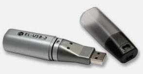
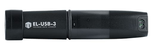
I’ve has a Lascar Electronics EL-USB-3 Voltage Data Logger for over 20 years and it works fine with no issues connecting to EasyLog software.
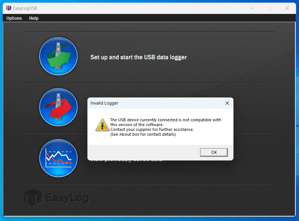
When I bought a replacement laptop, I downloaded from Lanscar Electronics the latest USB software, version 7.7.0.0, however, I ran into connectivity issues:
I went through the trouble shooting guide after changing the Tekcell SB-AA02 battery, but still no luck, even though the device was recognised in Device Manager.
I spoke to Lascar technical support who suggested the EL-USB-3 was faulty and needed replacement, this seemed odd as it was the software causing the issue, not the logger.
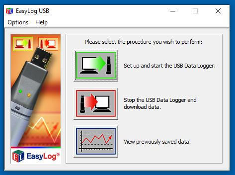
As luck would have it, I had a zip download from 2010 of version 5.53 and tried this on my Windows 11 laptop and it worked!
It seems as a rule of thumb that the latest all black loggers will work on the new software, whereas, the legacy silver loggers will need earlier software to work.
I’ve attached a link to EasyLog USB v5.53 software zip download – HERE
I have always loved the look of the Nixie tube and as an amazing Christmas gift from my better half, I got a Nixie clock kit to build.
The kit was from pvelectronics , also included in my gift was a GPS time receiver, Plexiglass case and PSU, assembly instructions for the main parts are below:
The packages came quickly and the contents were well packed as you would expect, assembly instructions and user guide are downloaded as no documentation comes with the kit.
Fig 1 – 5v regulator circuit
The assembly instructions are incredibly comprehensive, the build is designed in such a way that ‘stop and test’ points are used, enabling verification before moving on to the next build stage.
Fig 1 for example shows the components mounted to test the 5v regulation stage once 12v is applied.
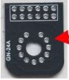
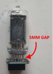
The only element of the build I struggled with was ensuring that the Nixie tube sits above the PCB by 5mm as per the instructions.
The problem is once all the Nixie tube wires are threaded through the PCB, I needed a way of not only getting the correct gap, but to ensure the tube is level in all planes, to solve this I used the 12 way SIL Socket Strips which come in the kit.
NOTE – This does mean going slightly ‘off-book’ to complete as otherwise you will have already soldered them to the main PCB.
I discovered is you slide SIL sockets from both sides through the Nixie tube wires between the PCB until the black plastic is touching the glass and PCB and then using light pressure on the PCB allows soldering knowing that the tube will be spot on.
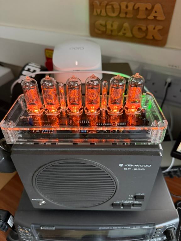
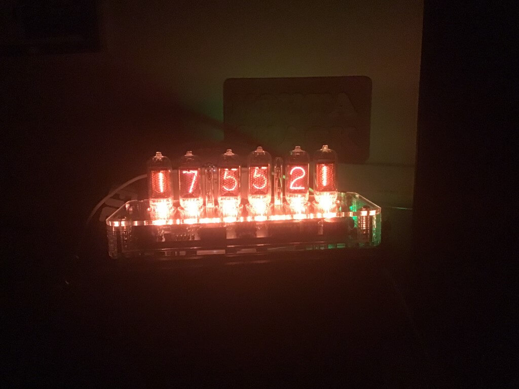
Completed clock looking brilliant and I’m very please with how it looks and all the features it has, for example the LEDs under the tubes can have there colour set to change every hour if you wanted too, as it is, I’ve set mine to orange (Red-3, Green -1 & Blue-0).
The only build variation from original, was to reduce the brilliance of the green power led, I replaced resistor R7 from 270Ω to 3.3kΩ.
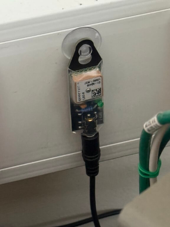
The additional GPS module only had 4 components to solder, the main GPS processor was already mounted on the PCB.
The GPS module connects to the Nixie clock and its a bit unnerving waiting for the green ‘sync’ led to come on 🙂
The Plexiglass case finishes the kit off in my option, giving that ‘class’ look as well as functionally keeping dust of the board.
I have no hesitation in recommending this kit and no, I’m not sponsored.
A couple of weeks before the car was due for an MOT the indicators lights on the dashboard started playing up, the following blog is how I quickly sorted it, if I had more time, I would have used less bright LEDs.
Apparently this is a common problem with Citroen C1 where the indicators work, but the dashboard turn lights either do not work or become intermittent.
Like most people I went onto YouTube and the issue pointed to the steering wheel stalk switch which I duly bought from eBay, and after watching more videos on how to change this, I was very please with my efforts until I tested it and the issue was exactly the same!
How to Diagnoise
Do both dashboard indicators come on when the Hazard Warning button is pressed and are they both stable when lit.
If the dashboard lights are OK with the hazards but ‘flakey’ with the indicator switch, the problem is the steering wheel stalk and a replacement is about £18 and you will need a pair of bent long nose pliers.
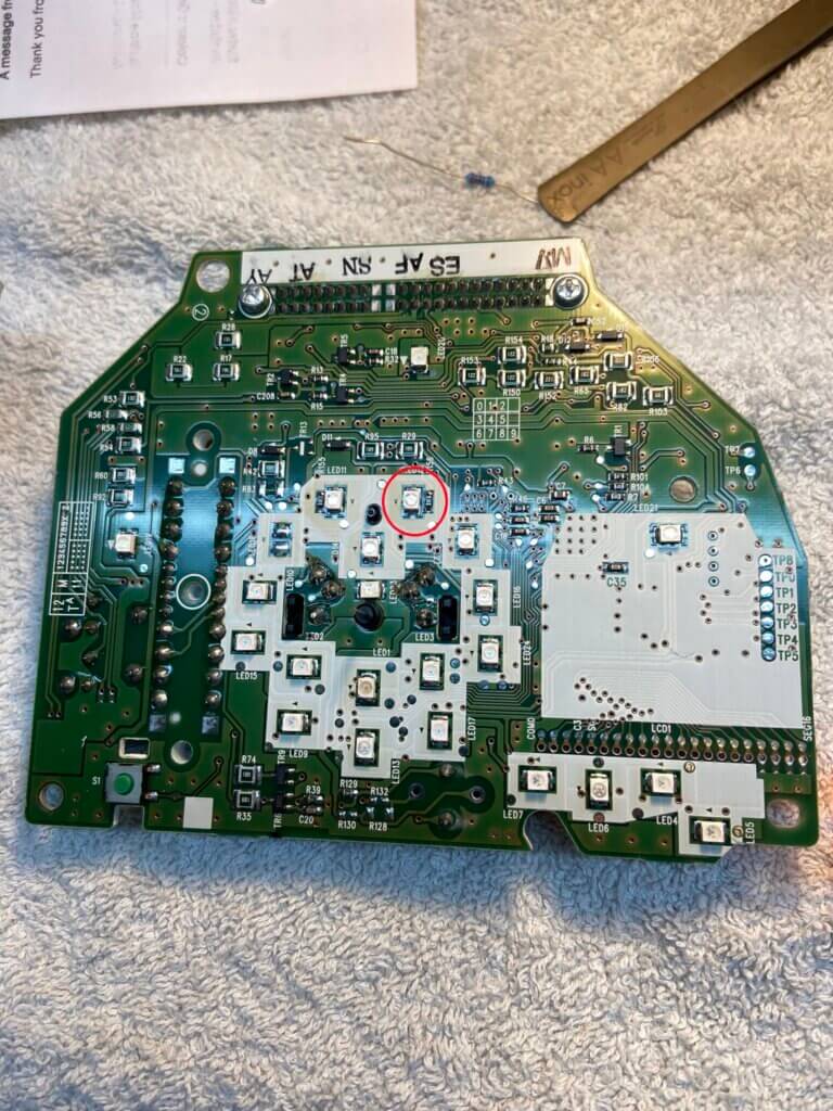
3. If the dashboard turn lights do not light at all or flicker or go very dim, this means the LED in the display cluster has failed or is failing, this was the case with me.
The red circle shows the LED which has failed for the Right Indicator, the LED type is a surface mounted 1210 GREEN colour, (I swopped out the left LED while I was at it).
I bought 10 LEDS from eBay for less than £2, I bought super bright LEDs by mistake, should have got normal brightness, not a big problem but it would have been better on the eyes at night with less bright ones.
Great update from Alistair:
“There are others available from LEDPERF (https://ledperf.co.uk) that have brightness rating of 140mcd …..this is much less distracting! Bit more expensive (0.63p each) ..but really does a good job.”
In preparation for changing them I also bought a 15w soldering iron with a fine pointed tip as these LEDs are tiny.
I already had a de-soldering suction iron from Aliexpress which worked brilliantly to unsolder the dashboard display to get to this point.
The LED is sat on top of a small screw and I found it a bit of a struggle as I didn’t realize how much my hand shakes, but managed it in the end 🙂
Everything worked fine when I plugged everything back together, BUT I made a mistake when I refitted the speedometer pointer, this meant removing the clear cover and pointer, turning the ignition ON, then pushing the pointer on the spindle at the zero MPH mark, I must have moved the spindle and after putting the pointer on, the servo speed motor couldn’t calibrate as it was hitting the milometer reset button.
This was an easy fix, but still a pain to do after I had though everything was working.
Hope this helps somebody else and thanks again Alistair for sharing your experience.
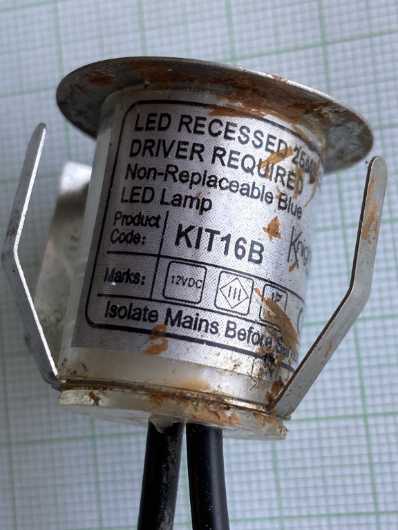
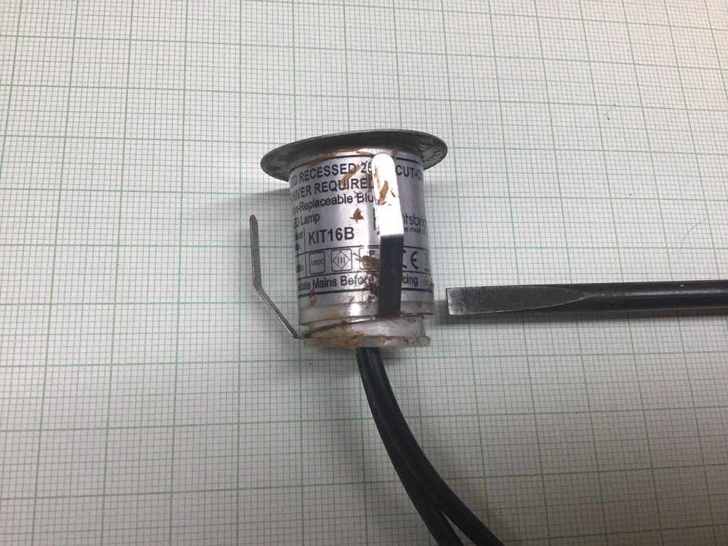
I bought two sets of the GL KIT16B garden walk over LED lights from TLC Electrical for my decking, each set comprises of 10 LED lights and a 12v transformer, the cost of each kit was £31.40.
I had these installed for about a year but due to an electrical problem which caused an overvoltage, the lights stopped working.
The choice was to buy new kits or try and repair them 🙂
The case does say Non-Replaceable Blue LED Lamp and this turned out to be incorrect.
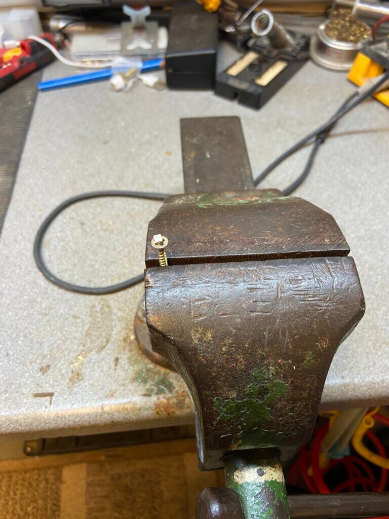
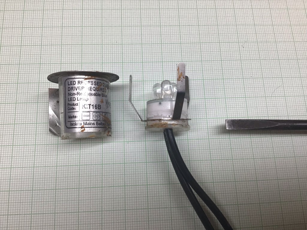
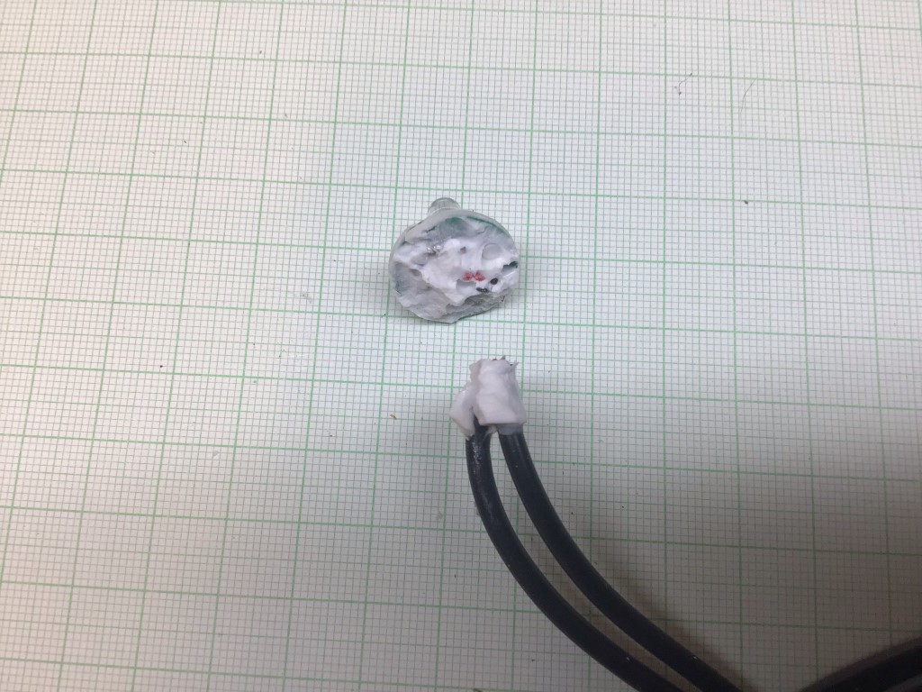
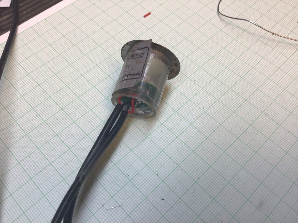
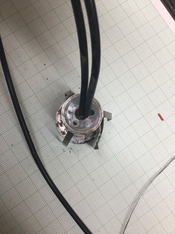
First job was to separate the base from the lamp body, it looks like they used an RTV (Room Temperature Vulcanizing) sealant. With gently persuasion using a screwdriver blade, the body came apart.
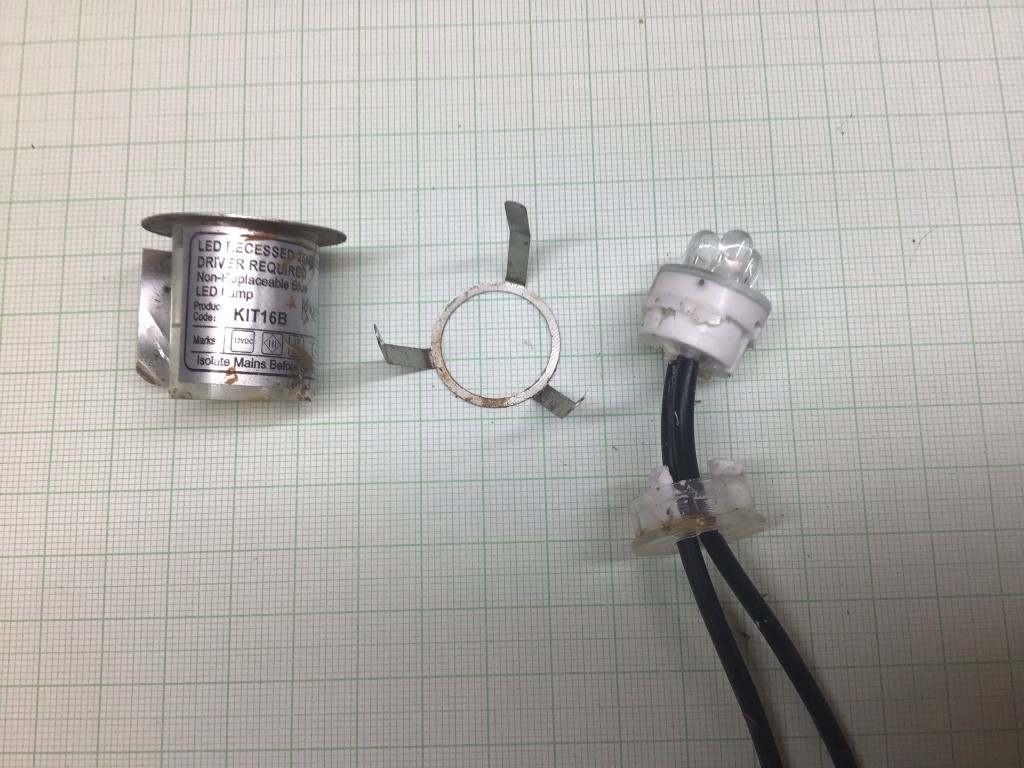
In order to get at the circuit board, base of the lamp need to be separated, this was done by simply pulling it apart.
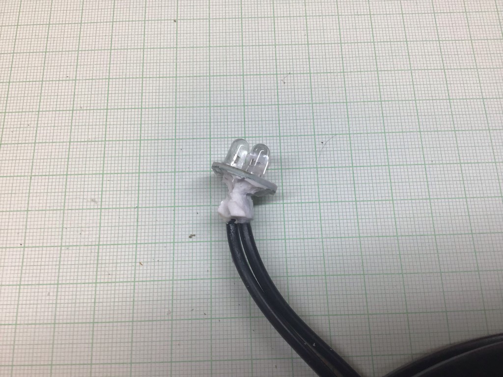
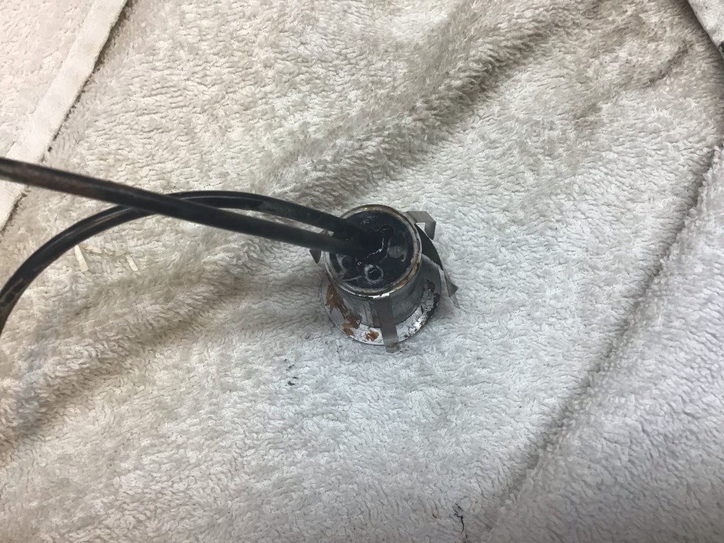
I got a fair bit of sealant of by using my fingers, the next step was to cut off the cables allowing more access to the PCB.
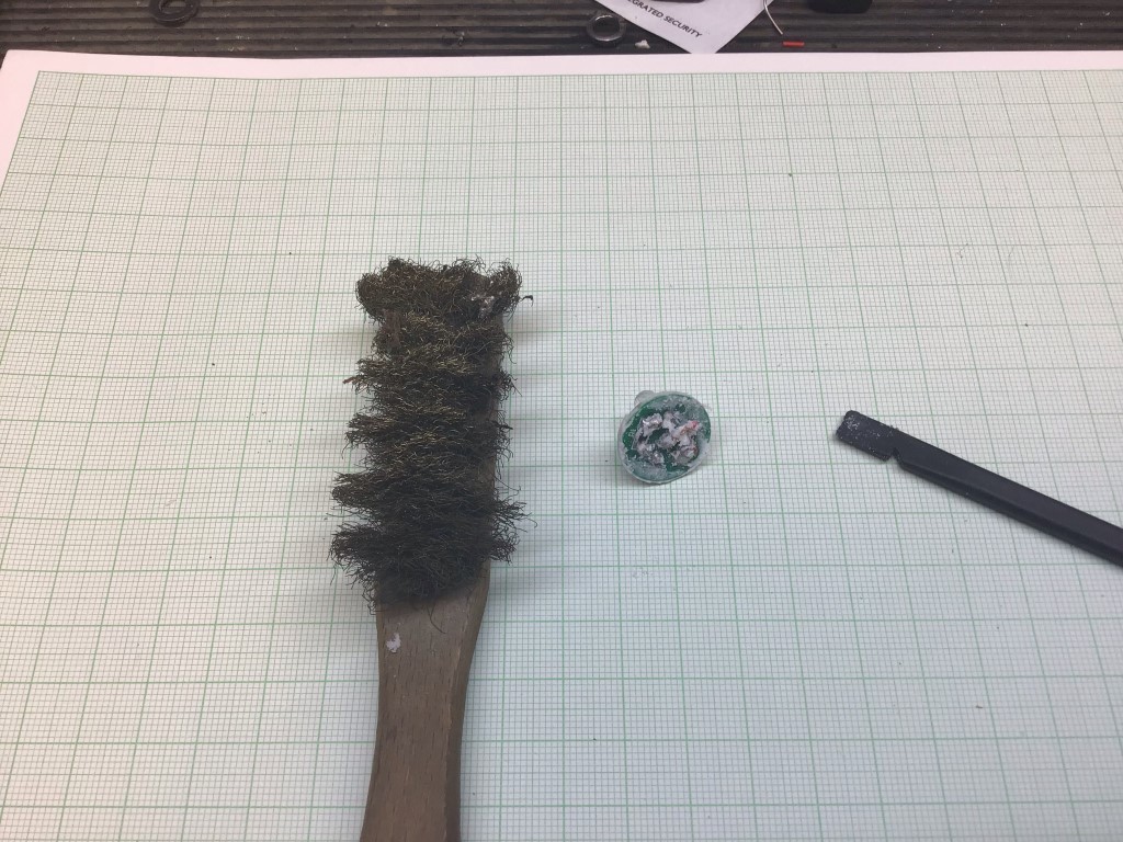
I used a Spudger to scrape off as much as I could before using a Brass brush.
The PCB was now nice and clean ready to unsolder the duff LED’s and SMT resistor which was open circuit.
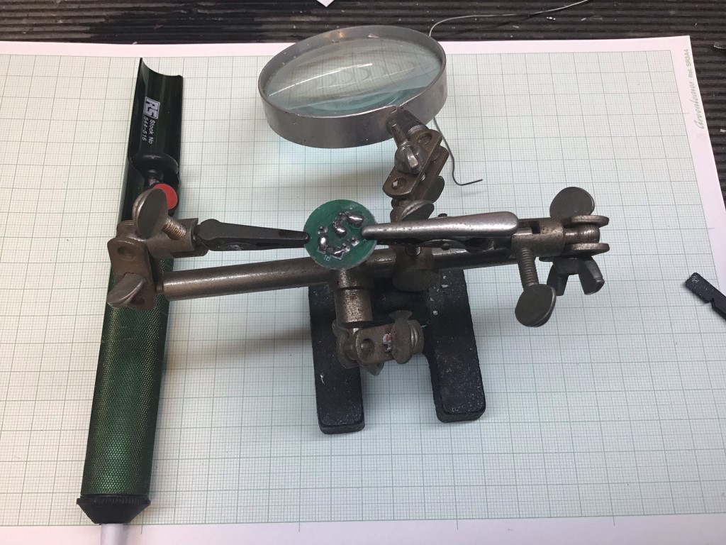
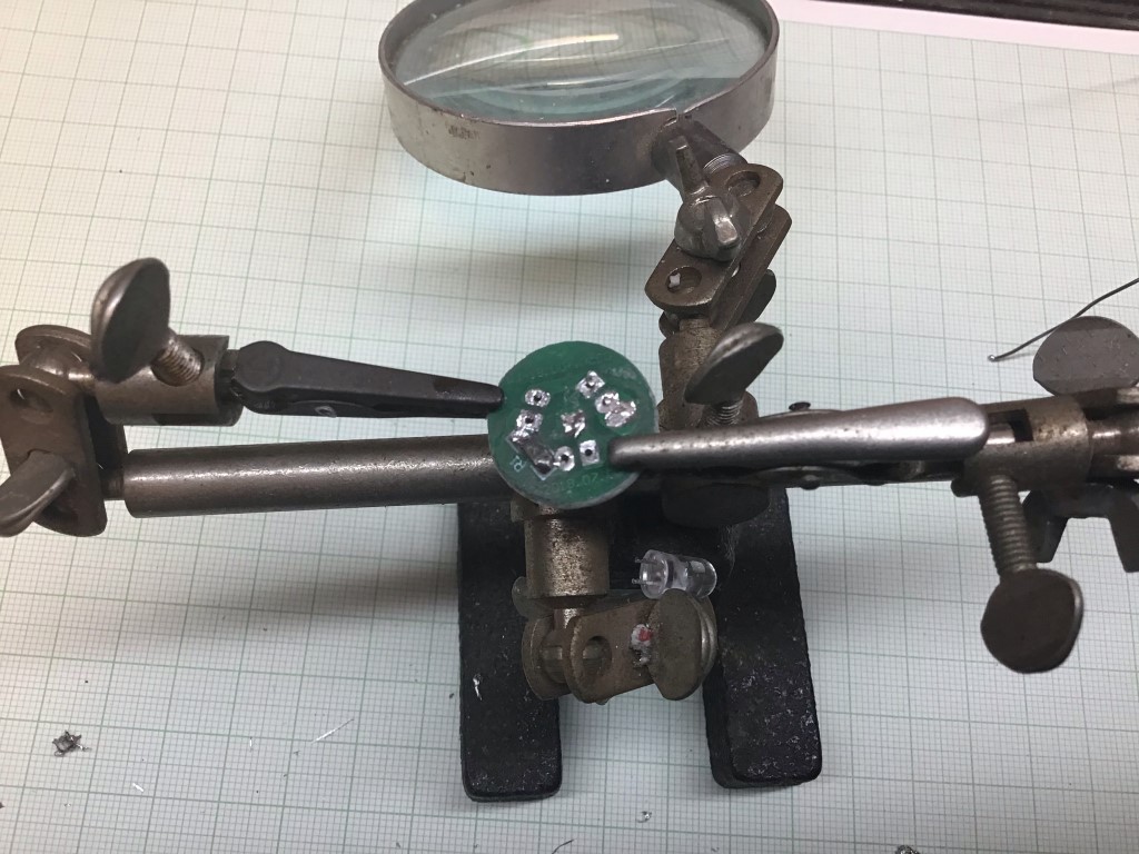
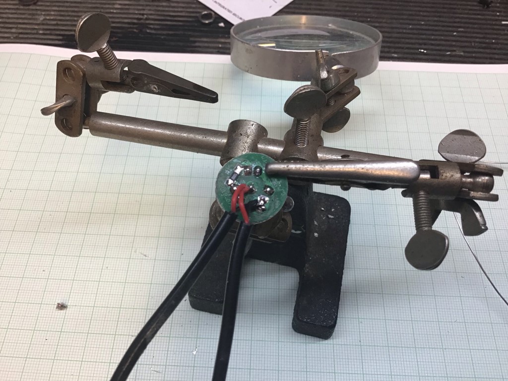
I’ve had this Helping Hand for more years than I care to remember and is perfect for this type of work.
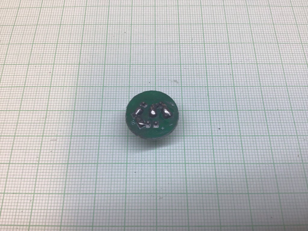
All the LED’s have been unsoldered, I used a solder pump for this, all that is left is the damaged resistor to remove.
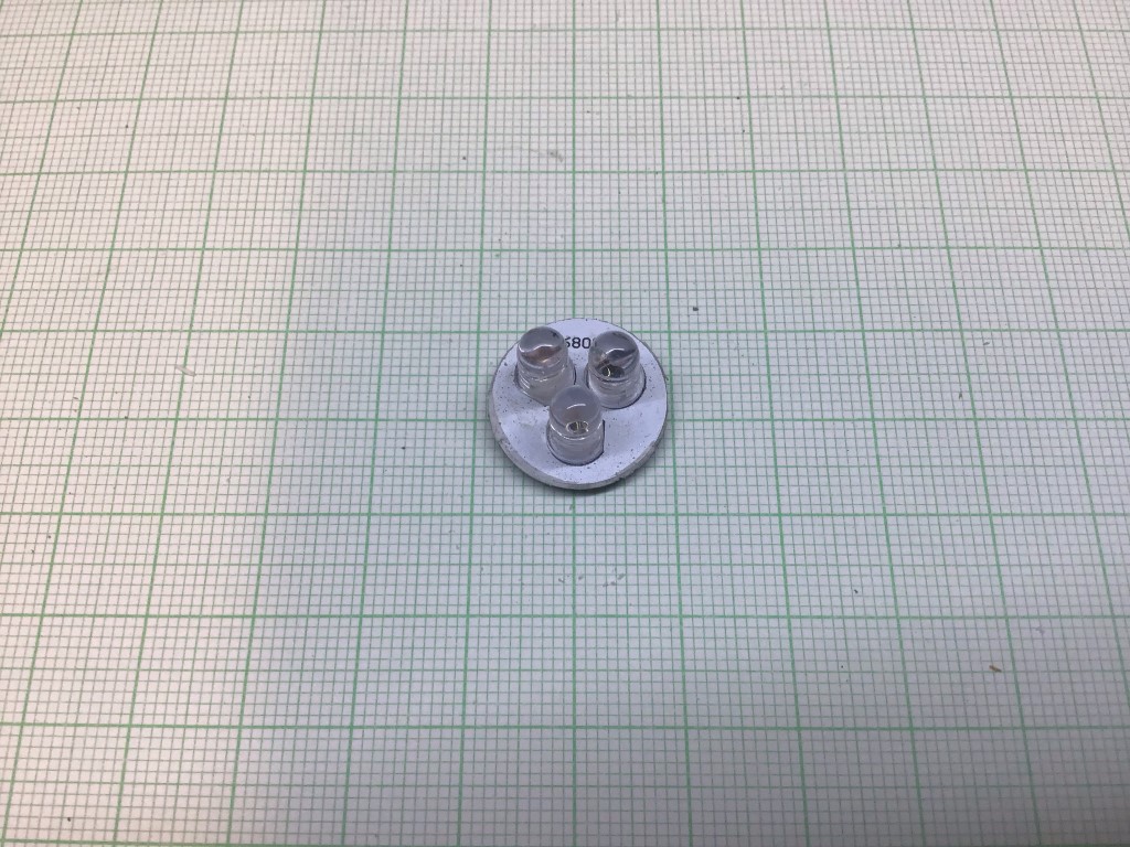
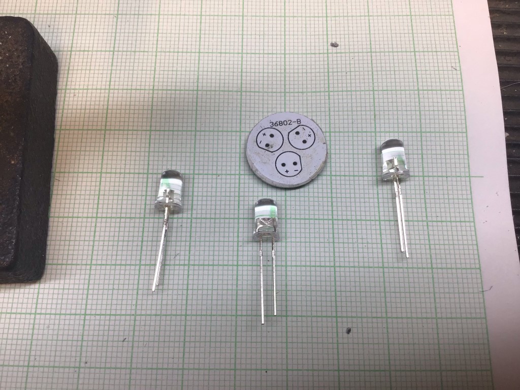
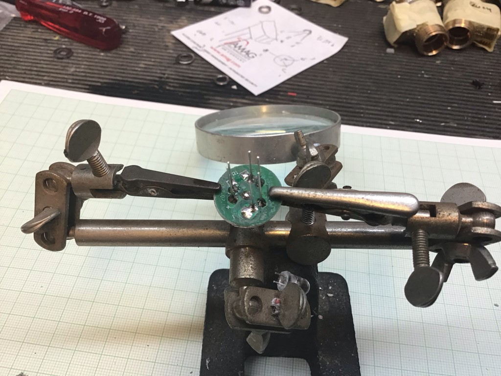
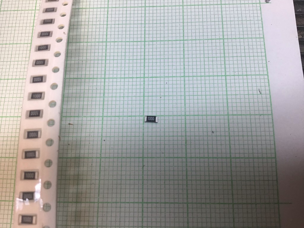
New LED’s ready to solder in, as you can see the PCB is printed with the orientation of the LED legs and LED body.
In the picture above I was soldering in Blue LED’s, however, I took the opportunity to change the colour in 8 of the lights to green to match the other garden lights.
LED’s, soldered in ready for the legs to be cut off and the resistor to be fitted.
The resistor needed was a 100 Ohm Type 1206 Surface Mount Device.
Once the resistor was in, the connecting cables can be reattached.
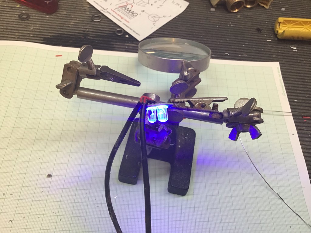
A quick test before reassembly.
With the PCB pushed back inside the light body, it’s important not to forget the holding clip for the next stage.
All pushed back into place ready to be sealed up.
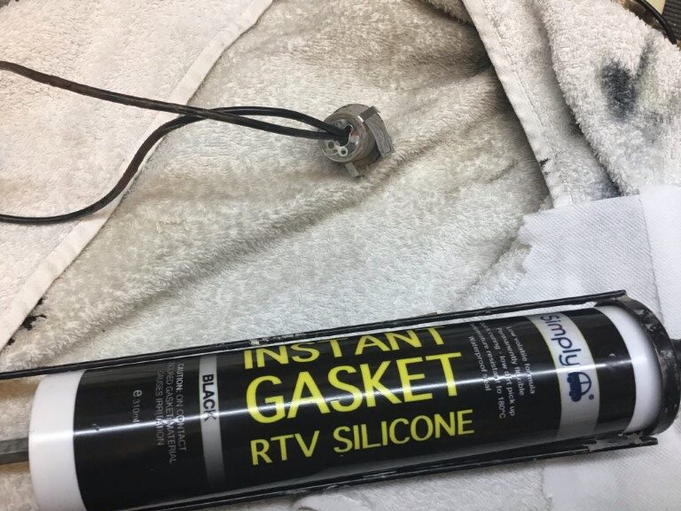
I used RTV Gasket silicone which cost £3.32, this is prefect as a potting compound.
Completed refurbished LED light, total time from start to potting is about 10 minutes.
The LEDs are 5mm and are very cheap off eBay, I could have fitted a number of different colours, but Blue and Green was fine, Knightsbridge only make Blue, White and Warm White in this model range, but don’t let you put this off after seeing this blog.
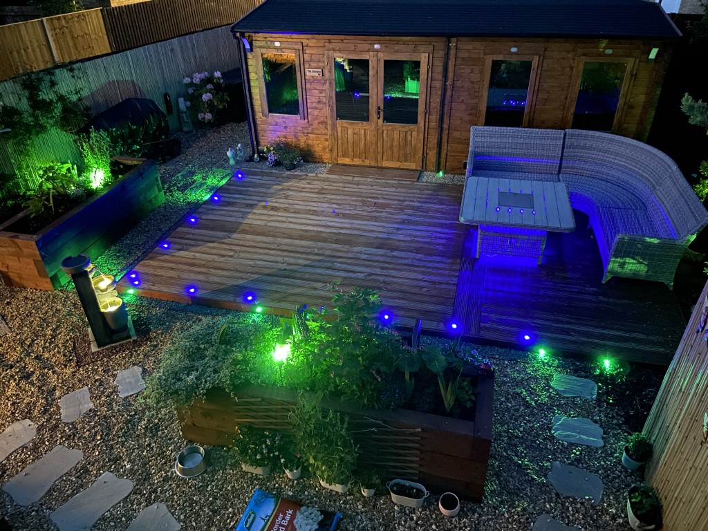
Finished look with the green deck lights pointing outwards illuminating the paths from the deck, really pleased with the finish and how easy and cheap it was to do.
As a DIY home improvent project, I’m installing electric mat underfloor heating, whilst researching this I noted in the American market they sold a device called ‘Loudmouth‘ which warns of damage to to the heating cable during installation, rather then complete the floor only to find the heating cable was not working!
In the UK underfloor heating manufactures sell a version of ‘Loudmouth’, the prices vary from £9.99 to £30.00, I bought one online for £10.49 inc P & P after searching the internet in vain for a schematic in order to build one. (Damage-Sensor-Instructions).
As I’m installing more than one mat at the same time in different areas, I thought I’d simulate the one I bought and make a quick blog.
The parts were from eBay apart from those I had in the workshop, total cost £5.61:
4.5v (3 x AA) battery box with integral switch – £1.84
S8050 Transistors (Pk 5) or J3Y for SMD – £0.99
3v Buzzer (Pk 2) – £2.38
Resistors, LED, Veroboard already had.
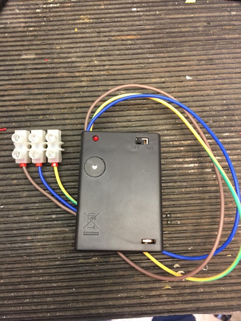
Completed home made unit
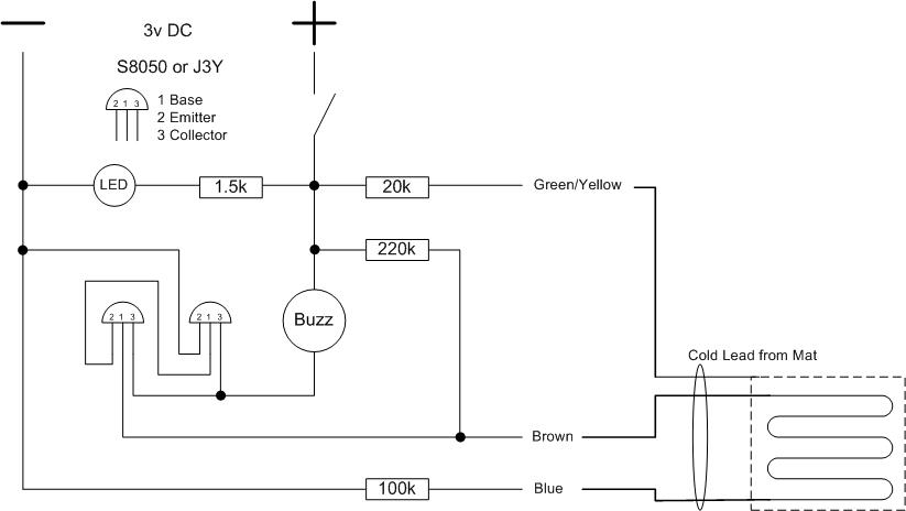
Alerter Schematic
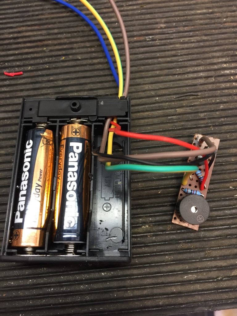
All the parts fit neatly inside a battery box in the space left by the lack of one of the AA batteries, the unit works on 3v, so only two batteries are needed.
How To Use
Before unboxing the underfloor heating mat, measure and record the mats element resistance and resistance to the sheath, if this meets with the manufactures instructions, the alert unit can be connected after the mat is laid out.
Turning on, the LED will light and the buzzer will sound, the LED stays permanently lit, this acts as a confidence check that the unit has power.
Connecting the Brown and Blue wires together will silence the buzzer, touching the Green/Yellow wire to the connected Brown and Blue wires will cause the buzzer to sound.
In use, the Brown, Blue and Green/Yellow wires will be connected to the underfloor heating mat cold lead cable wires, the heating element wires are a continuous circuit, damaging the cable will break the circuit causing the buzzer to sound and alerting you to stop and check and repair the damage before progressing. The element wires are contained within an earthed sheath, the Green/Yellow monitors the sheath for shorts circuits to the elements, and will again alert if damage is detected.
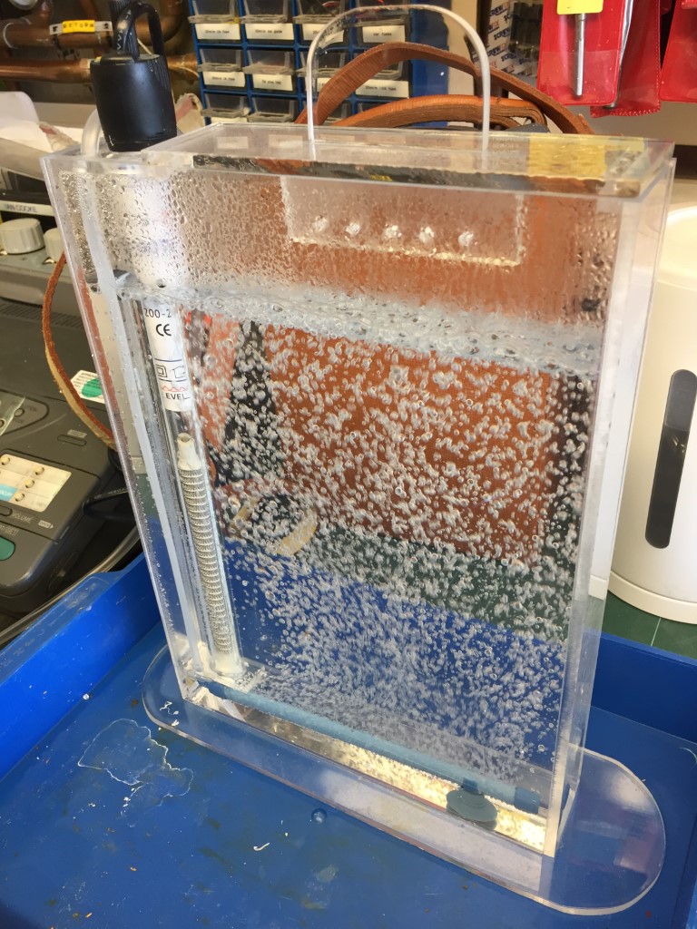
I decided to build a PCB etch tank for some up and coming projects, so this is a quick blog on how I did it.
For ease I bought four pieces of 5mm thick clear Acrylic (Perspex), each piece pre cut to A4 size (210mm x 297mm) off eBay for £5.41 per sheet, the height of 297mm is also ideal to accommodate the immersed heater.
You only actually need three sheets, from this two full sheets are each side with the third sheet requiring cutting to form the sides of the tank, whats left over is the base, the idea is minimal cuts and make best use of factory cut edges to cement forming a leak tight joint.
I used a tenon saw to cut a 40mm strip the length of the sheet (40mm x 297mm), once cut, I turned the sheet round and marked 40mm in from the remaining factory cut edge, and cut the second wall strip.
The piece left over, I used as the base of the tank after shaping it using a jig-saw with an Acrylic cutting blade, I found that better results for straight cuts were with the tenon saw, rather than the jig-saw even though I used a straight edge.
With all the pieces cut, the edges were rubbed with 1200 grip paper and cleaned with IPA, before being cemented.
The cement used was Model X Pro plastic weld, 50ml costing £6.69 from eBay, this came with an syringe applicator which was invaluable for accurate use.
I used butt joints ensuring factory cut edges only are cemented to the flat surface of the sheets, once the parts are checked for alignment, the plastic weld which is like water, is applied and ‘wicks’ along the joint giving a really strong joint, reaching full strength in 24 hours.
I did make a couple of brackets for the heater and a lid for the tank out of the remaining Acrylic sheet, but this was not absolutely necessary.
Using the dimensions above, you should end up with a tank which is 45mm deep, 215mm wide and 297mm high, to cover the heating elements ‘water line’ will take 1.3 litres of etchant and will cope with 1.5 litres.
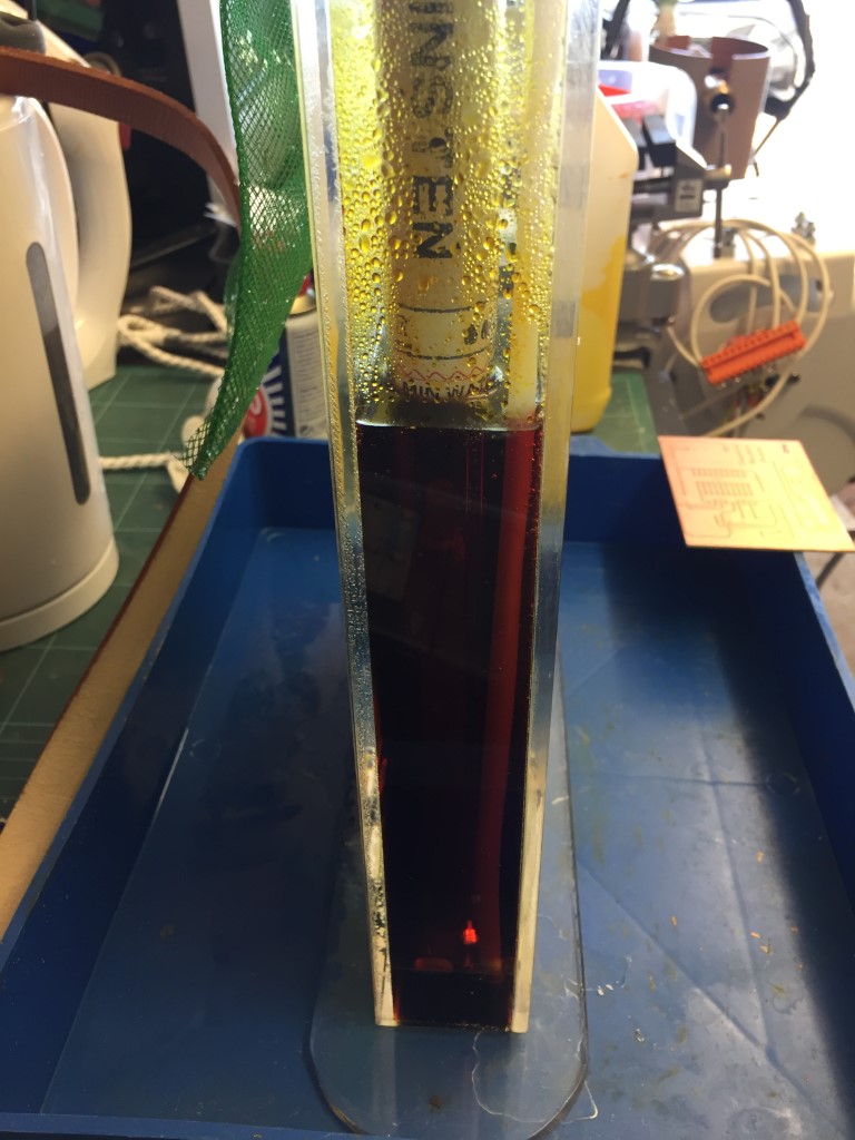
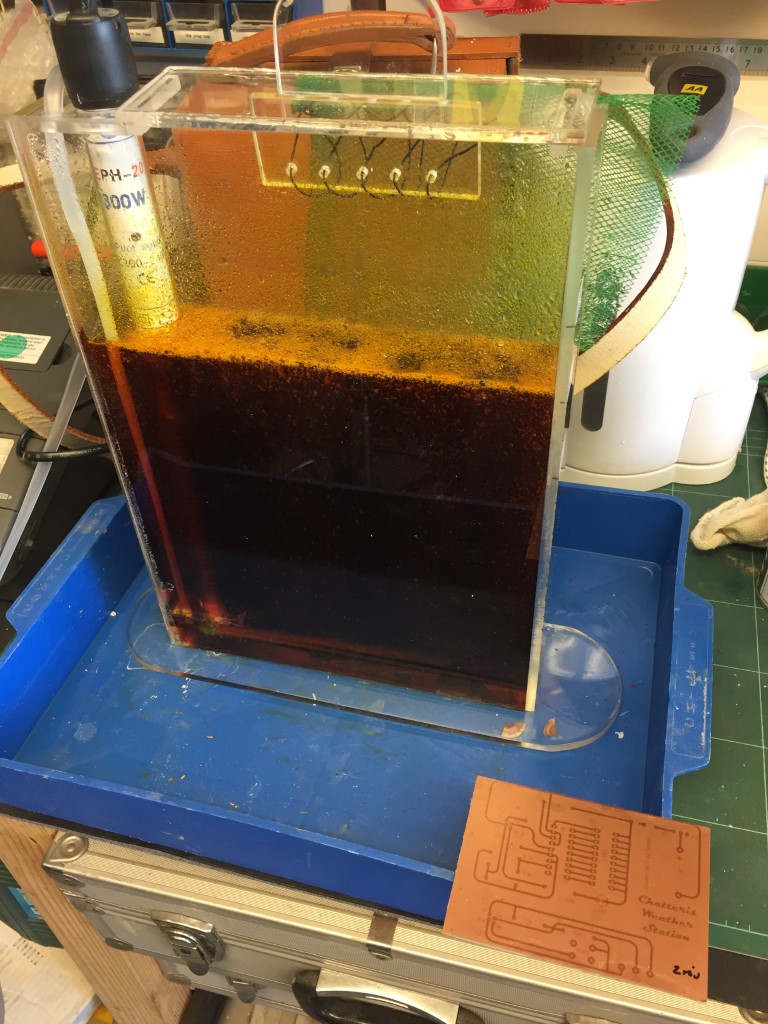
From a local aquatics shop I bought 6mm air line, air pump and bubble wall to agitate the solution, the heater is a 300W 230v EPH-20 Kinsten Etchant version from eBay and was quite expensive at £16.53, this has adjustable higher temperature settings than normal fish tank heaters (33°C to 55°C), the tank is set for 40°C.
Exposed photo resist board ready for immersion in Ferric Chloride to remove the unprotected copper.
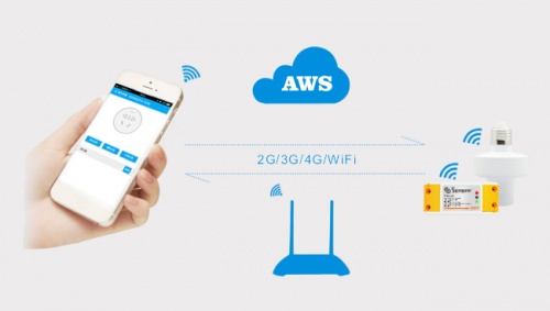
Home automation is “The Internet of Things”. It simply means the way all devices or appliances are networked together to provide customers with a seamless control over their home equipment.
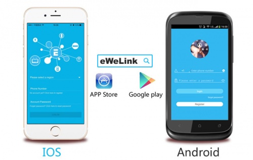
Sonoff is an affordable device that provides users with smart home control. It is a WiFi based wireless switch that can connect to a wide range of appliances. Sonoff transmits data to a cloud platform through the WiFi router, which enables users to remotely control all the connected appliances, via the mobile application eWeLink. The cloud server of Sonoff is Amazon AWS global server.
Sonoff makes all home appliances smart. As long as the mobile has network, users can remotely control the appliances from anywhere at any time. Another feature available is to set timing schedules for the appliances, which can include countdown, scheduled on/off, and can thus, help users maintain an easy life.
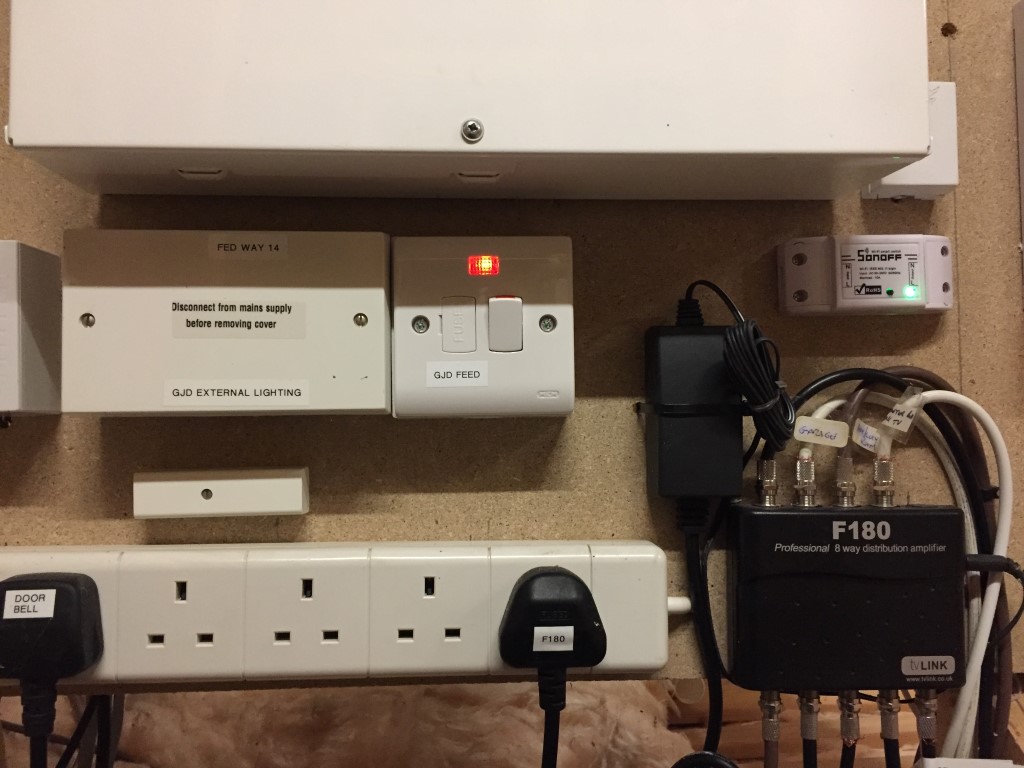
The unit I needed to modify was the Sonoff Basic, this is a simple WiFi enabled unit which will switch 230v on or off, however, the application I needed was for it to switch a set of voltage free contacts, as these cost less that £6.00 each, its worth a go with the soldering iron.
The unit is very compact and before starting, I paired it with my mobile phone and checked that it worked correctly.
The top simply clips off the base and the PCB comes apart without any fixings after cutting the paper security seal.
The relay has the Sonoff sticker on it and the mains is switched through the relay, the board uses double sided tracks for this.
The relay was desoldered and removed from the PCB, this then allowed access to the tracks which were cut with a Dremel.
The picture shows the bottom of the PCB with the tracks cut from the 230v input and a shorting link to complete the relay switching circuit.
This shows the relay back in place and the top tracks cut, the modification now allows a voltage free changeover which will be used to bring on my low voltage triggered external lighting.
After playing with a Programmable Logic Controller (PLC) to operate my radio mast, I decided to build a simulator in order to better understand the capabilities of the EASY PR-18DC-DA-R.
I wanted the simulator to have 16 inputs, either momentary or switched and the ability to import signals including an embedded 4 – 20mA current.
I had a sloped project enclosure already, so I made a dimensioned drilling template.
Once the template was stuck down, the pilot holes were drilled, template removed and holes opened to the right sizes.
The template was created in Visio and I used layers, one of the layers was for switch position drilling and alignment cross-hairs, turning that layer off (missed one in I8!), allowed me to print on self-adhesive sticky Matte White Vinyl.
Using a sharp knife, I cut though the Vinyl and started fitting the switches, buttons, Output indication LEDs and 4 – 20mA injector.
Terminal posts next.
Front panel populated.
Wiring started.
After a couple of changes, the internal wiring is completed and loomed in.
The simulator uses 24v DC, I used a small 1.5A output switched mode PSU for this, fed via a chassis fuse holder with the supply from an IEC male socket, the output from the PSU is fused separately.
PLC simulator all powered up, the program in the PLC was legacy from my mast control project, this will be overwritten by downloading revised programs from xLogicsoft software.
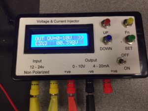
To complement the PLC simulator I bought a4-20mA Current Signal Generator 0-10V Voltage Generator Transducer Simulator for £19.00.
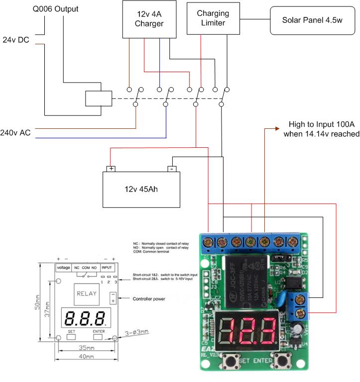
Link back to Radio Mast Automation – HERE where the EASY RL-V23 unit can just be seen attached to the lid of the mast controller.
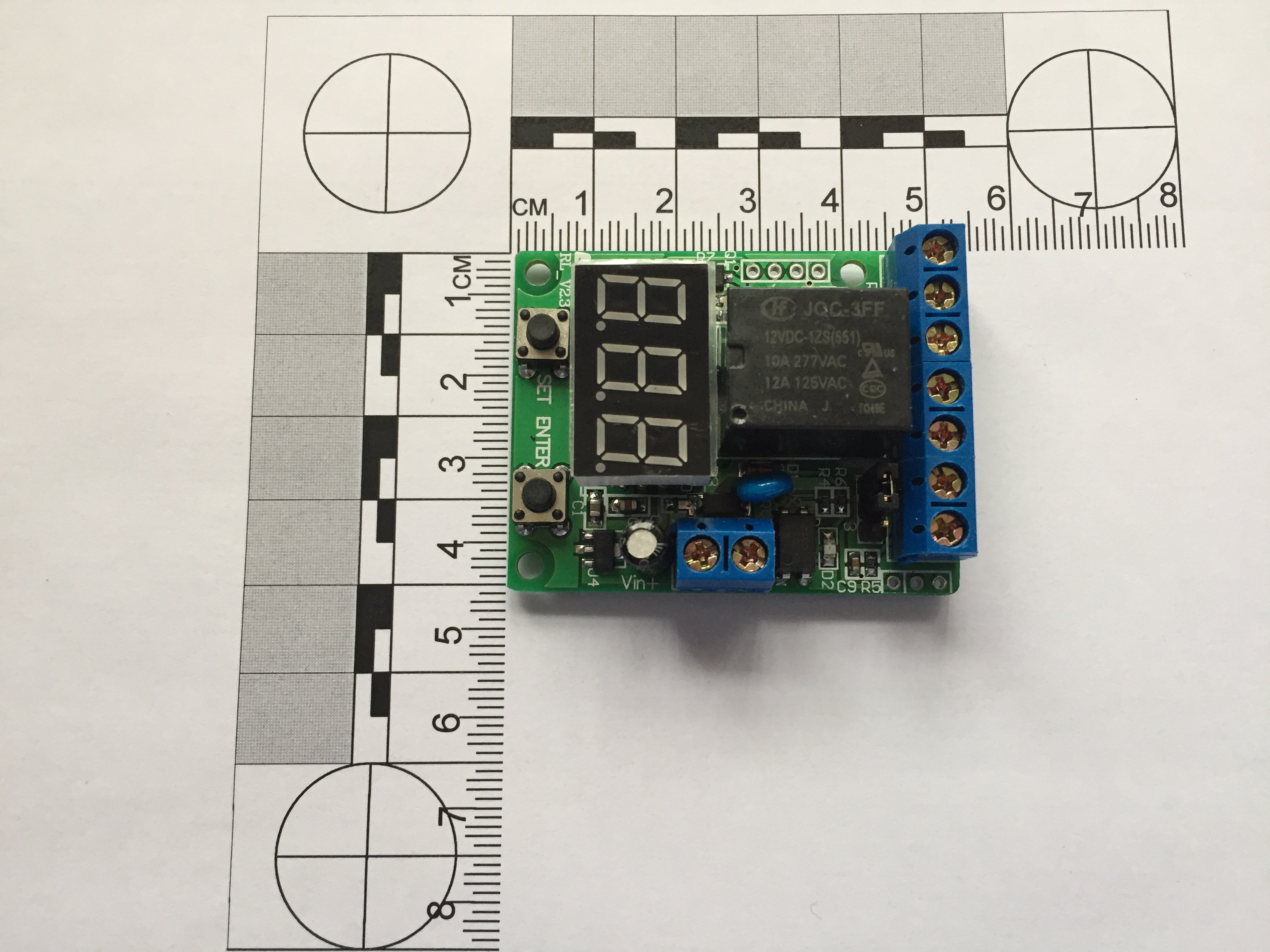
EASY Voltage Unit
The above module was from eBay and advertised as a ’12V Voltage Control /Delay Switch /OverVoltage /Under Voltage Protection Module’ for £4.92.
This unit is incredibly versatile, and I’ve included the operating instructions in the blog.
I have used this module to monitor the charging voltage of a battery, once the voltage has reached a pre-set value, an output will trigger to stop the charger.
Operating modes:
P-1: Timer ( 1-999 S / 1-999 Min)
P-2: Delay timer ( 1-999 S / 1-999 Min)
P-3: Voltage control relay ( control the load on/off)
P-4: Voltage control Timer- A (release first)
P-5: Voltage control Timer- B (close first)
P-6: Voltage range control relay
P-7: Voltage range control Timer
P-8: Set display off
Timing Range: 0-999 seconds or 0-999 minutes (0.1s-999s optional)
Voltmeter display range: DC 0-99.9 V
Voltage detection error: ± 0.1V
Operating Power: DC10~16V (5V,24V optional)
Relay parameters:
Coil Voltage: DC 12V (5V,24V optional)
A set of conversion (normally open and normally closed)
Contact load: 10A/277V AC or 10A/30V DC
Contact resistance: ≤ 100mΩ (1A 6VDC)
Mechanical durability: 10 millions
Electricity durability: > 100,000 (10A-250VAC)
Operating Temperature: -40 ~ 85℃
External signal input: (5~ 12V) or passive switch (9 levels delay time can be set)
Timer mode can set the relay contact close and release time, the implementation of a single timing loop
In voltage control mode, can preset upper and lower voltage values limits
Set display shut, the minimum current values are 6mA/12V (delay released)
The pre-set parameters can be saved after power off.
2 Operating modes:
Connect to power, LED digital tube displays words “E-A-Z-Y-t” in turn, system enter into the selection state, the initial mode selection is displayed as “P-0”, press the “SET” button to select “P-1~P-8” mode, press “ENTER” to enter the corresponding mode.while any mode running, press the “ENTER” button for 3 seconds, system will return to the mode selection state.
Press the “SET” and “ENTER” button to connect the power, the controller will be restored to factory settings.
2.1 Timer mode (P-1)
Press the “SET” button to select “P-1”, controller system will enter into the timer mode.
“P-1”/ “P-2”: 1-999 seconds /minute can be set.
Cyclic run:
In the timer mode, the user can set the relay’s close time T1 and the release time T2,such as setting T1 for 3 seconds, T2 for 7 seconds, the relay will be closed for three seconds then release for 7 seconds, cyclic run.
User also can set cyclic times.
When you have set the values of the T1 and T2 , the system saved the settings, the next time system will be loaded automatically T1 time to wait running.
Timer:
If you set T1 with a specified time, set T2 (release time) with 0, the relay will stop after the timer run T1 time, no longer running, it can be used as a timer, with running time end, the normally open contact of relay release, then press the “ENTER” button, the system re-start the timer for T1 time.
In timer state, you can use external switch or pulse signal input Interface on controller to start the timer (trigger).
Timer setting steps:
1) For the first time of set , select “P-1” time relay mode, LED digital tube display” 000 “;
2) Press the “SET” button, system will enter into the T1 time values settings first, the digital LED that wait for set flashing with 1Hz frequency, press “ENTER” to select the number of values, press the “SET” button for three times to enter the T2 time values settings, and cyclic times, press the “SET” button to exit the set state, the system waits to press “ENTER” button to start running.
3) In the time setting state ,time values’ unit can be switched to minutes unit or second unit, press the “SET” button to enter the time set by state (set LED digital tube flashing) ,at this time Press the “SET” button for 3 seconds to release ,the LED digital tube will light the right decimal points, it means that timing values with minutes unit, if the decimal point dose not light, it means that timing values with seconds unit.
4) After setting is completed, press the “SET” button to exit the setting state, press “ENTER” to start timing, if timing values is set with second unit, seconds values will display with countdown form. If timing values is set with minute unit, the right decimal point flashing with 1Hz frequency, means the countdown is running. While timer is running, the normally open contact of relay connected, the normally closed contact of relay disconnect, press the “ENTER” to halt run, press the “ENTER” for three seconds to return mode selection state “P-0”.
2.2 Delay timer (P-2)
The Setting method of “P- 2” is the same as “P- 1”, in the mode of “P-2”, the relay will first execute release of T1 time then closed with T2 time.
2.3 Voltage control relay mode (P-3)
In mode selection state(“P-0”), press the “SET” button to select “P-3”, then press the “ENTER” to enter the voltage comparison control mode, the controller will detect voltage from “VOL” Interface and display values (DC 0-99.9V),it also can be used as a DC voltmeter ,the default initial run state relay contact is closed (normally closed contact is disconnected, normally open switch on), press the “SET “button to set the three bit values, the LED digital tube is set to flashing with1Hz frequency, first to be set upper limit voltage values , press the “SET” button three times, lower limit values of voltage to be set,press the “ENTER” button to increase the number of values, the lower limit voltage can not exceeds the upper limit, press the “SET” button to make digital tube is no longer flashing, this time system enter into voltage control mode , the controller detects DC voltage from external input Interface , when voltage detection exceed the upper limit of the pre-set, the relay close (normally open contact connect ,normally closed disconnect), until the voltage drops below the lower limit pre-set, the relay will release (normally closed contact connect , normally open contact disconnect).
In voltage control condition, press the “SET” button for three seconds then release the button, the contact of relay state will be reversed. such as: the relay close when detect voltage below the lower limit voltage.
If the pre-set voltage upper and lower limits set to the same, such as 12.0V, when controller detect volts at 12.0 fluctuations may cause the relay contact frequent action, we recommend to set the voltage to maintain the difference between the upper and lower limits.
Note: The detection voltage terminal must connected reliable, have not loose wiring around the circuit board insulation ,may lead to the induced voltage detection values is not accurate.
2.4 Voltage control Timer mode (P-4 / P-5)
“P-4” or “P-5” mode is composed of “P-1” and “P-3” or “P-2” and “P-3”.When the system switched to “P-4” from “P-1”or“P-2”,it will enter the voltage control timer mode, the controller will detect voltage from “VOL” Interface ,when detect voltage exceed the upper limit of the pre-set voltage, the timer will start , until the volts drops below the lower limit pre-set , the timer stop.
If you set time in “P-1” mode previous, then enter the “P-4” mode , the relay will close with timer first ,then release, If you set time in “P-2” mode previous, then enter the “P-4” mode ,the relay release with timing then closed.
The difference between “P-4” and “P-5” is the relay’s Initial state, “P-4” mode relay release first, but “P-5” mode relay close first.
Press the button of “SET” last for 3 seconds, the timer will start in the case of the voltage is below the lower limit. the setting method of limit pre-set voltage, please refer to section 2.3.
For example:
(1) In P-2 mode , set T1 005, T2 000, then enter P-4 mode , voltage detection exceed the upper limit of the pre-set the relay will close after 5 seconds, voltage drops below the lower limit pre-set the relay release Immediately.
(2) In P-1 mode , set T1 005, T2 000, then enter P-5 mode, voltage below the lower limit pre-set the relay close immediately, voltage detection exceed the upper limit of the pre-set the relay will release after delay 5 seconds.
Voltage control logic can be reversed with press SET key for 3 seconds.
2.5 Voltage range control relay (P-6)
If the voltage controller detects exceed the upper limit of the pre-set voltage, or the voltage drops below the lower limit pre-set voltage, the relay will close, otherwise the relay release between upper limit and lower limit range. Press the button of “SET” last for 3 seconds, the relay reversed. The relay will close between upper limit and lower limit.
2.6 Voltage range control Timer (P-7)
If the voltage controller detects exceed the upper limit of the pre-set voltage, or the voltage drops below the lower limit pre-set voltage, the relay will run follow time relay mode that has been set in P-1 or P-1 mode previous.
When voltage values between the upper limit and lower limit range, press SET key for 3 seconds, relay reversed between close and release (ON/OFF).
For example:
In P-1 mode, set T1 005, T2 000, then enter P-7 mode, set relay close between upper limit and lower limit range. When voltage below lower limit or exceed upper limit, the relay will release after 5 seconds.
2.7 Set display shut (P-8)
The display shows “d-0” means keep bright, you can press the button of “SET” set 0-9 minutes for display shut.
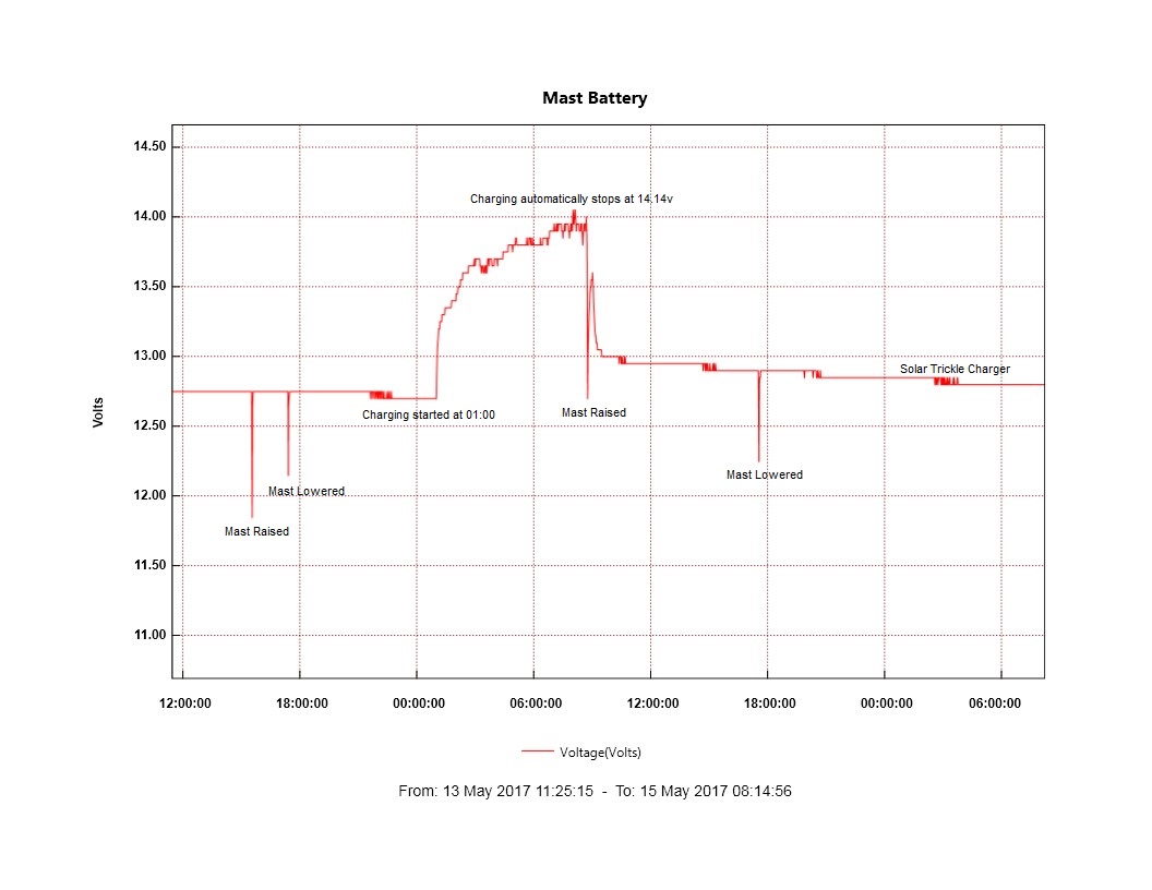
Graph showing operation of raise and lower including the automatic charging cycle.
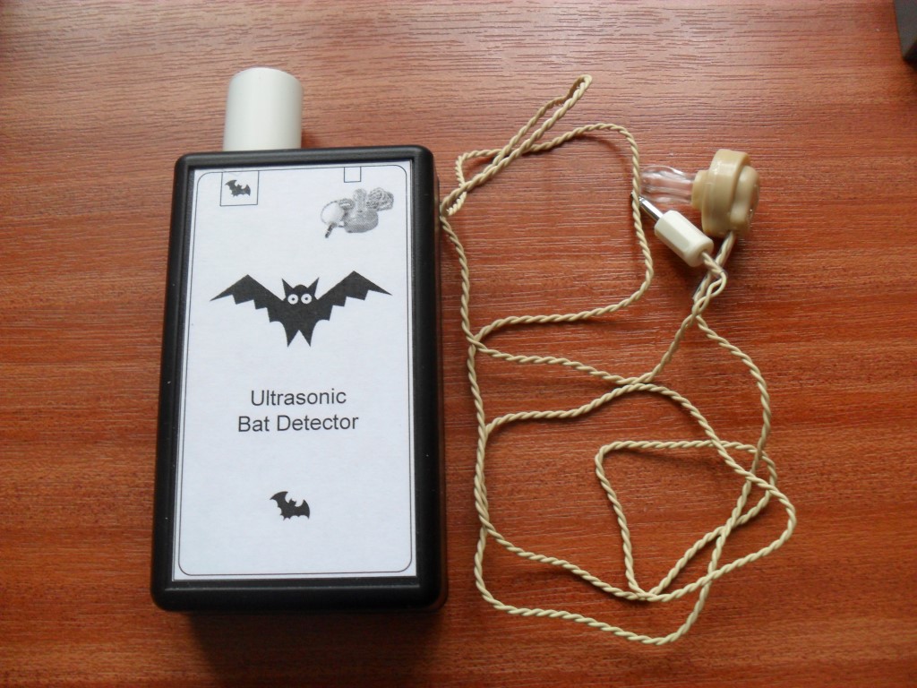
For a few years now we have had bat which regularly flies round the garden, Googling about bats I came across a bat detector circuit from Tony Messina.
Tony’s site (http://pw1.netcom.com/~t-rex/BatDetector.html) is packed with interesting information and a link to the UK where you can buy the printed Circuit Board if you didn’t want to use veroboard.
The PCB is from Lee Rogers (mail: lrogers222@hotmail.com) in the UK for £5 including p&p, the majority of the parts are available from Rapid Electronics , things out of stock at Rapid can easily be found on eBay.
The testing and adjustment was done by pointing at running water or rattling keys and tweaking the volume to a comfortable level as you go.
The total cost of the project was £28 and took about an hour to construct.
Just got to test it on the real thing now 🙂
Update 12 August 18
Well it took a while for Norma the bat to pay us a visit, but she did and the detector worked just fine, very impressed with it 🙂
A blog about stuff that interests me or I have done.
We use cookies on our website to give you the most relevant experience by remembering your preferences and repeat visits. By clicking “Accept All”, you consent to the use of ALL the cookies. However, you may visit "Cookie Settings" to provide a controlled consent.
This website uses cookies to improve your experience while you navigate through the website. Out of these, the cookies that are categorized as necessary are stored on your browser as they are essential for the working of basic functionalities of the website. We also use third-party cookies that help us analyze and understand how you use this website. These cookies will be stored in your browser only with your consent. You also have the option to opt-out of these cookies. But opting out of some of these cookies may affect your browsing experience.
Necessary cookies are absolutely essential for the website to function properly. These cookies ensure basic functionalities and security features of the website, anonymously.
Cookie
Duration
Description
_GRECAPTCHA
5 months 27 days
This cookie is set by the Google recaptcha service to identify bots to protect the website against malicious spam attacks.
cookielawinfo-checkbox-advertisement
1 year
Set by the GDPR Cookie Consent plugin, this cookie is used to record the user consent for the cookies in the "Advertisement" category .
cookielawinfo-checkbox-analytics
11 months
This cookie is set by GDPR Cookie Consent plugin. The cookie is used to store the user consent for the cookies in the category "Analytics".
cookielawinfo-checkbox-functional
11 months
The cookie is set by GDPR cookie consent to record the user consent for the cookies in the category "Functional".
cookielawinfo-checkbox-necessary
11 months
This cookie is set by GDPR Cookie Consent plugin. The cookies is used to store the user consent for the cookies in the category "Necessary".
cookielawinfo-checkbox-others
11 months
This cookie is set by GDPR Cookie Consent plugin. The cookie is used to store the user consent for the cookies in the category "Other.
cookielawinfo-checkbox-performance
11 months
This cookie is set by GDPR Cookie Consent plugin. The cookie is used to store the user consent for the cookies in the category "Performance".
CookieLawInfoConsent
1 year
Records the default button state of the corresponding category & the status of CCPA. It works only in coordination with the primary cookie.
PHPSESSID
session
This cookie is native to PHP applications. The cookie is used to store and identify a users' unique session ID for the purpose of managing user session on the website. The cookie is a session cookies and is deleted when all the browser windows are closed.
viewed_cookie_policy
11 months
The cookie is set by the GDPR Cookie Consent plugin and is used to store whether or not user has consented to the use of cookies. It does not store any personal data.
Functional cookies help to perform certain functionalities like sharing the content of the website on social media platforms, collect feedbacks, and other third-party features.
Performance cookies are used to understand and analyze the key performance indexes of the website which helps in delivering a better user experience for the visitors.
Analytical cookies are used to understand how visitors interact with the website. These cookies help provide information on metrics the number of visitors, bounce rate, traffic source, etc.
Cookie
Duration
Description
_ga
2 years
The _ga cookie, installed by Google Analytics, calculates visitor, session and campaign data and also keeps track of site usage for the site's analytics report. The cookie stores information anonymously and assigns a randomly generated number to recognize unique visitors.
_ga_92TJCVGJP2
2 years
This cookie is installed by Google Analytics.
_gat_gtag_UA_48800884_1
1 minute
Set by Google to distinguish users.
_gid
1 day
Installed by Google Analytics, _gid cookie stores information on how visitors use a website, while also creating an analytics report of the website's performance. Some of the data that are collected include the number of visitors, their source, and the pages they visit anonymously.
CONSENT
2 years
YouTube sets this cookie via embedded youtube-videos and registers anonymous statistical data.
is_unique
5 years
StatCounter sets this cookie to determine whether a user is a first-time or a returning visitor and to estimate the accumulated unique visits per site.
is_visitor_unique
2 years
StatCounter sets this cookie to determine whether a user is a first-time or a returning visitor.
sc_is_visitor_unique
2 years
StatCounter sets this cookie to determine whether a user is a first-time or a returning visitor.
Advertisement cookies are used to provide visitors with relevant ads and marketing campaigns. These cookies track visitors across websites and collect information to provide customized ads.
Cookie
Duration
Description
NID
6 months
NID cookie, set by Google, is used for advertising purposes; to limit the number of times the user sees an ad, to mute unwanted ads, and to measure the effectiveness of ads.
VISITOR_INFO1_LIVE
past
A cookie set by YouTube to measure bandwidth that determines whether the user gets the new or old player interface.
YSC
session
YSC cookie is set by Youtube and is used to track the views of embedded videos on Youtube pages.
yt-remote-connected-devices
never
YouTube sets this cookie to store the video preferences of the user using embedded YouTube video.
yt-remote-device-id
never
YouTube sets this cookie to store the video preferences of the user using embedded YouTube video.
yt.innertube::nextId
never
This cookie, set by YouTube, registers a unique ID to store data on what videos from YouTube the user has seen.
yt.innertube::requests
never
This cookie, set by YouTube, registers a unique ID to store data on what videos from YouTube the user has seen.