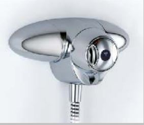
I have always struggled with water temperature control on my Trevi CTV thermostatic shower valve, typically it was always too cold and we ended up running the cold sink tap at the same time as having a shower, in order to reduce the cold water pressure, this then allowed warm water flow.
My first thought was that the problem was within the mixer tap, I downloaded the manual and disassembled the mixer to check that the hot water strainer was clear and nothing obvious was wrong, what I did notice was the temperature limiting plastic ‘stops’ were missing.
These ‘stops’ are a means of maximum temperature regulation and also act as an ‘anti scold’ devices, so the removal of them meant the installer knew of a problem 🙁
I went on the UK Plumbers Forum to ask advise about this and the answer came back almost immediately.
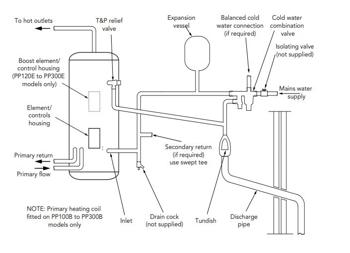
In order to explain, I need to show how my domestic hot water is plumbed:
Looking at the diagram above, the high pressure mains water supply enters from the right into a balancing valve, this valve performs three functions:
Reduces the incoming cold water pressure to 3.5 bar to feed the unvented cylinder
Provides a cold water connection at the same water pressure as the unvented cylinder
Contains a Pressure Relief Valve which will discharge to drain if the pressure exceeds 6 bar.
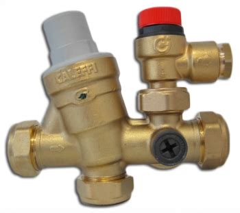
Monoblock/Balancing valve.
My unvented cylinders reducing valve doesn’t have a cold water take off, so instead of fitting one, the original installer simply took the cold fee to the mixer shower valve directly from the incoming supply, which is at a greater pressure than the pressure reduced hot water, so it would never have worked properly from day one.
The person who fitted it must have known this, so removed any overtemperature controls, what an idiot!
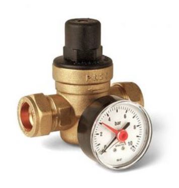
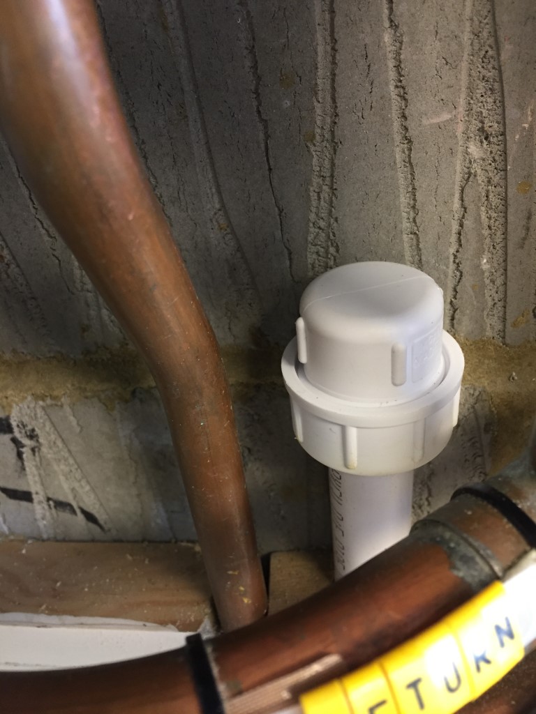
In order to fix this, I needed to either fit a balancing valve and re-pipe the shower to the cold take off, or, fit a 3.5bar pressure reducing valve (PRV) near the shower, this is what I did.
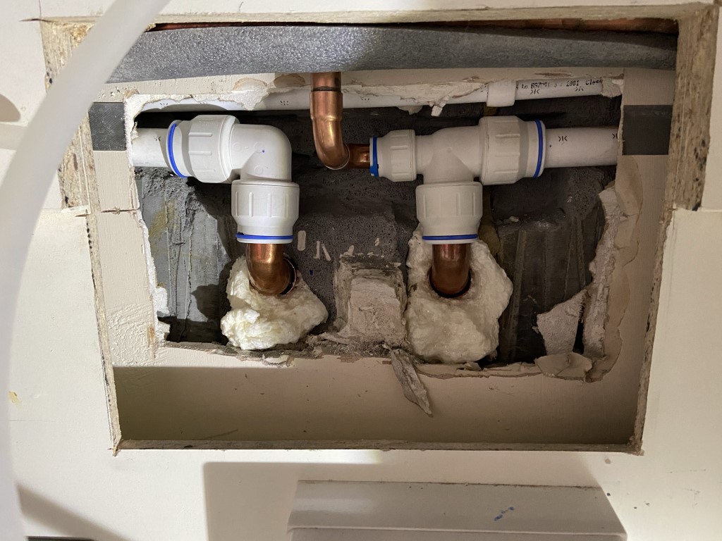
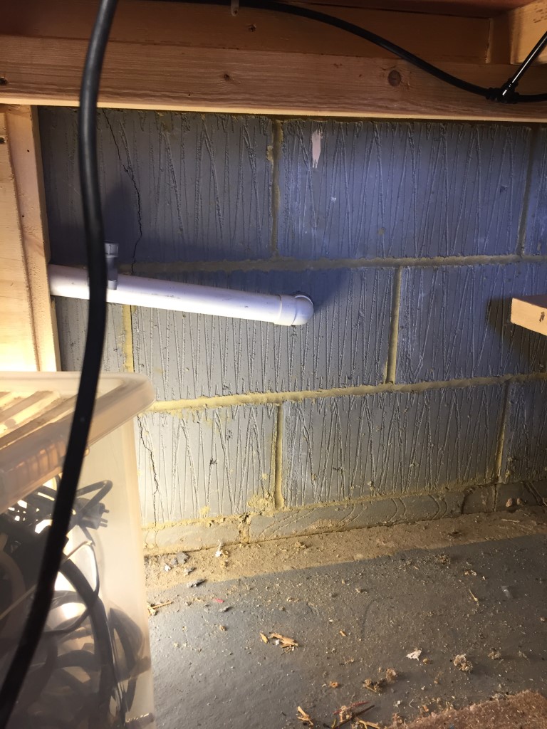
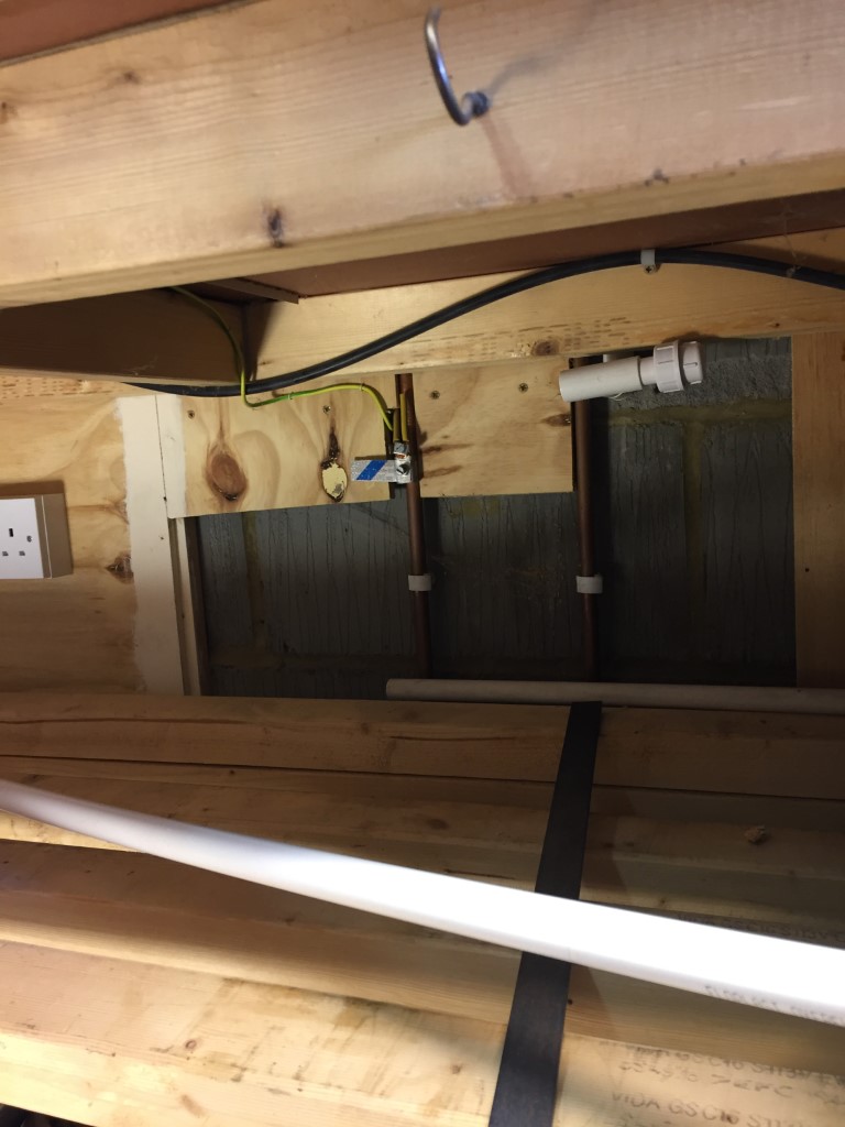
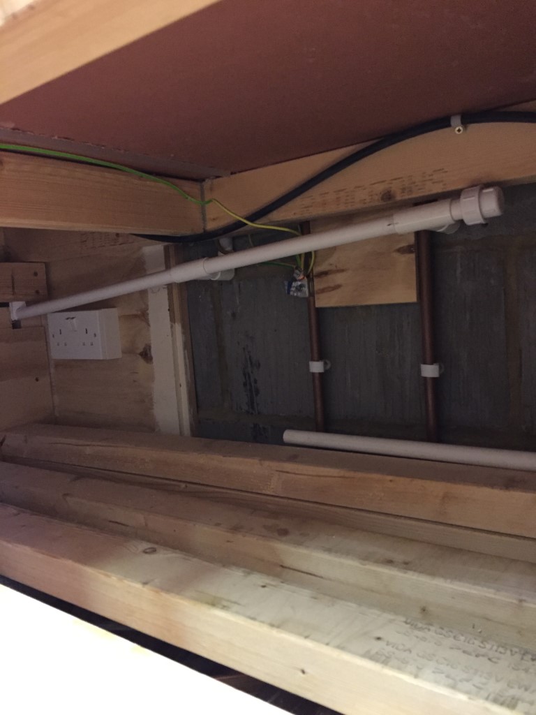
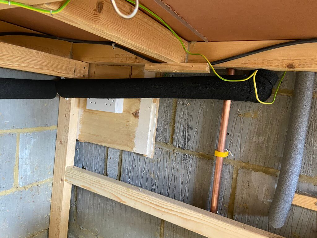
The plastic pipes from the shower mixer run under the landing floor, so I used a multitool and cut an access hatch in the floor to locate the pipes, turning on the shower for hot water whilst holding the pipes, soon identified the hot one.
The PRV needed to be fitted to the cold water, so the stopcock wat turned off and water drained by turning on the kitchen taps, once drained the plastic pipe was cut and inserts fitted.
I used a short length of 15mm copper pipe tails from the PRV inlet and outlet compression fittings and made the connection to copper/plastic pipe with ‘push fit’ sockets.
The hatch cover was then screwed down and marked up, so anyone lifting the carpet back will know what’s under the hatch.
It was not an expensive fix, and its made a huge difference, don’t know why I put it off for so long.
My central heating system has 13 radiators with 12 having Thermostatic Radiator Valves (TRV), and I decided a couple of years ago to replace the existing wax capsule TRVs with intelligent Hive ones which I did.
Stock Honeywell TRV Head
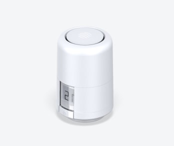
Hive Intelligent TRV replacement head
Installation of the Hive TRV was very straightforward, the existing heads are removed by unscrewing the knurled nut and the Hive supplied adapter is screwed into place on the valve body, the Hive TRV then screws to this and using the App is enrolled onto the heating system.
Hive TRVs have picked up negative reviews, I think this was due to launching the product before it had been fully beta tested, that said, most of the wrinkles have now been ironed out and I enjoy the benefits individual radiator temperature control and scheduling gives me.
My main issue has been that the Hive TRVs, which are controlled via a smartphone app, and this keeps requesting that the TRV’s need calibration, which I have put down to the age and condition of the existing radiator valves.
I could temporarily free sticking valve pins by ‘tapping’ and adding oil or WD40, but they would always stick again, and they did look a bit mangy, also my boiler pressure was dropping very slowly over time and I put this down to TRV valve leaks, so it was time for action!
Honeywell VT15 TRVs
The TRVs installed when the house was built (circa 2002) are VT15:
Unfortunately the valve has no serviceable parts and therefore no replacement insert is available which is a nonsense to be honest, as it forces you to either buy a complete valve assembly with TRV sensing head or search for a vendor who will sell the valve body only.
After much searching, I found a seller on eBay of VT15 valve bodies only at £6.99 each, so I bought what I needed which is a lot cheaper than buying a complete assembly for £15 each and throwing half of it away.
I had no intention of changing the valve body on the radiator as it would only introduce more work and an elevated risk of leaks from pipework joints, only the insert needed to be changed, so when I received the valves the inserts had to come out.
I had to use a 19mm socket in an Impact Screwdriver to remove the inserts from the new valves as they are insanely tight, so make sure the valve is held tightly in a solid vice before trying this.
Fitting Inserts
After switching power off to the boiler, I drained the water out of the heating system, this was easy in my case as the downstairs radiators had drain valve lockshields.
After removing the Hive TRV head, you can see the hexagonal head of the valve insert, using the Impact Screwdriver, the old insert was swiftly removed and the new insert fitted and carefully tightened with a 19mm ring spanner.
As the insert uses ‘metal- to metal’, mating face with the valve body to form a seal, I used V2-Plus jet lube jointing compound on the threads and joint face as a precaution against leaking.
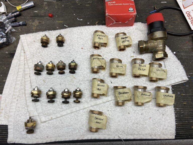
Removed inserts from the heating system.
I changed 11 inserts, on investigation 1 was OK, 10 were sticking or stuck in the closed position and of the 11, 7 showed signs of leaking.
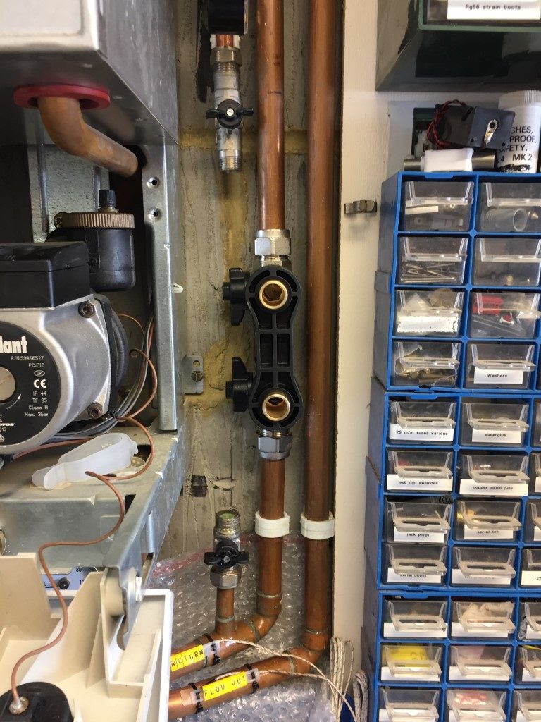
While the system was drained I changed the Automatic Bypass Valve (ABV) for a better quality Honeywell DU145, although my boiler has an inbuilt ABV for boiler protection, it is prudent to have one installed with TRVs as the external ABV is designed to maintain a minimum pump flow rate through the boiler as the individual radiator TRVs close and to manage boiler over-run when zone valves close, rather than ‘dead heading’ the pump forcing the boiler ABV to open.
When all the inserts and the ABV was fitted, Fernox F1 inhibitor was added via Magnaclean filter chamber and the system filled with water, circulated and vented.
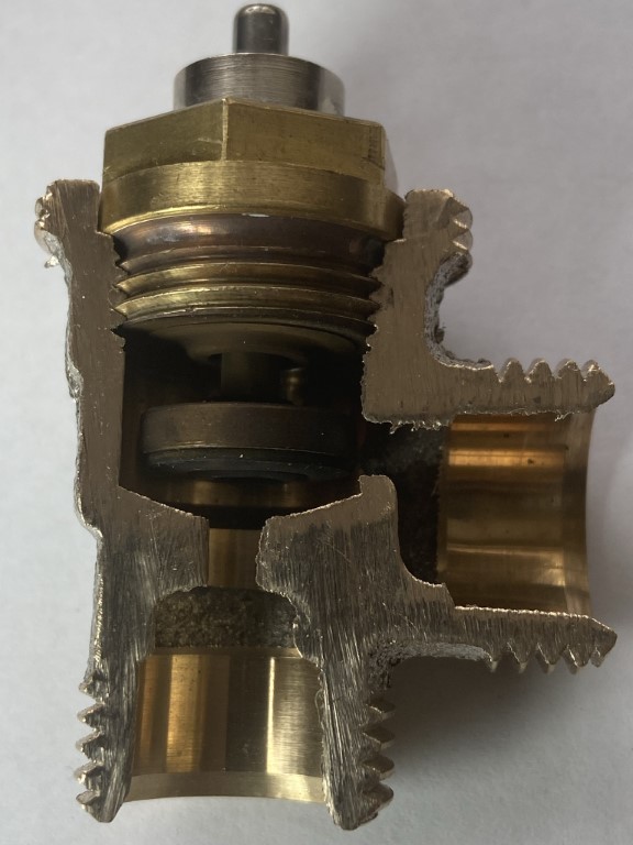
Not being a plumber, I decided to cut open a TRV valve body to see how it work and where it fails.
Jointing paste was used on the threads and contact face of the insert just in case of a bad seal
Insert Operation.
Water from the heating system enters at the bottom of the valve body, as the valve plunger is away from the valve seat (room asking for heat), water will pass and exit to the radiator.
If the pin on the top of the insert, (which is under spring pressure to keep the plunger lifted), is slowly pressed down, this will begin to restrict the water flow to the radiator as the plunger lowers into the valve seat, eventually closing the central heating water off completely to the radiator.
The job of the TRV head is to push down on this pin based on the rooms ambient temperature.
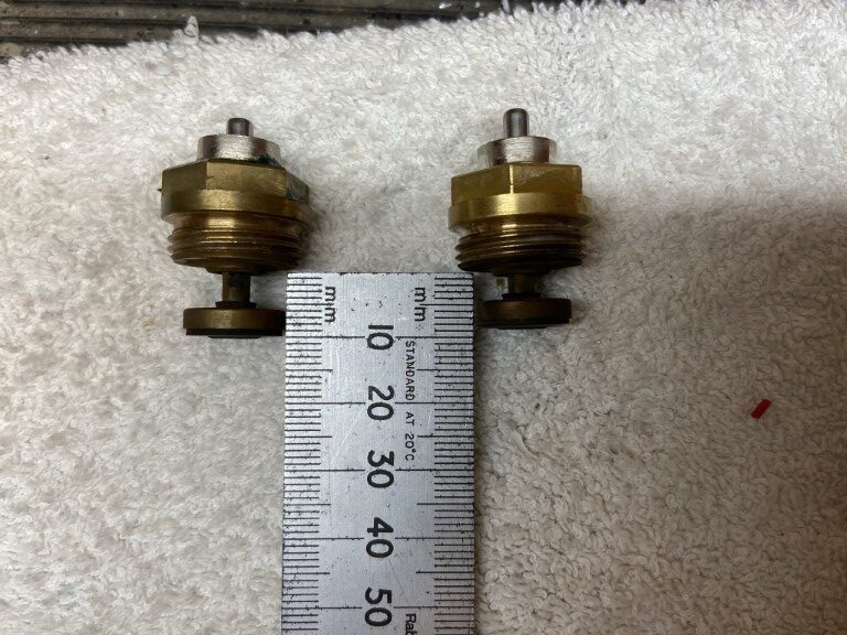
The movement of the pin is not very much at all :
The plunger on the left is stuck in the lowered position, the one on the right is OK as the internal spring has overcome friction and lifted the plunger.
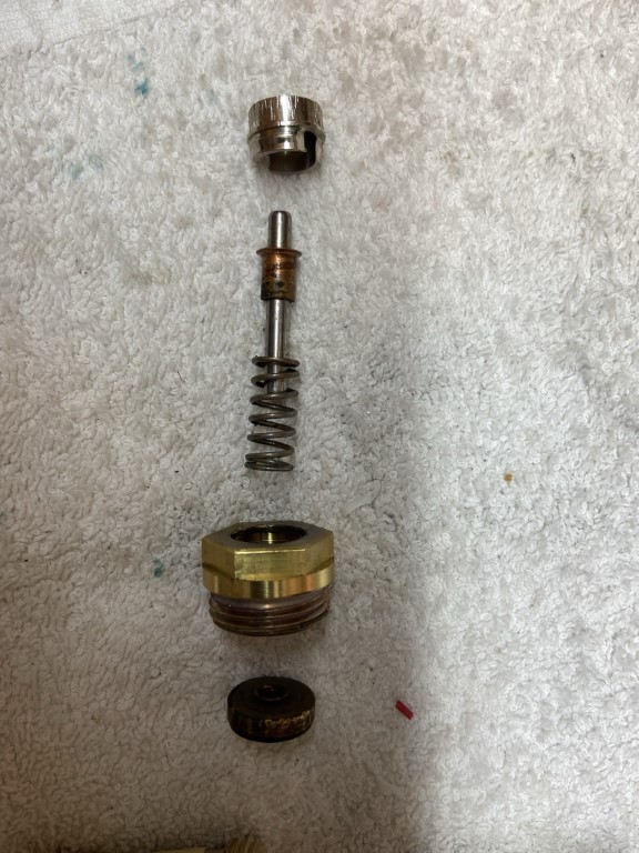
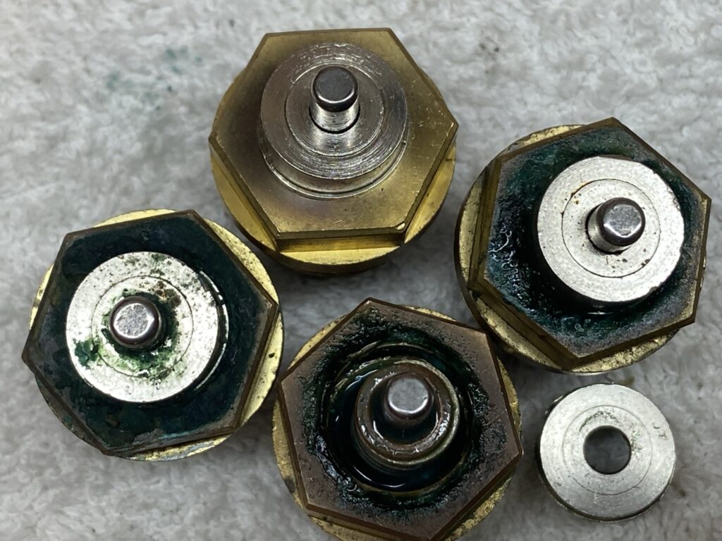
So what’s inside an insert?
Bottom View
Top View
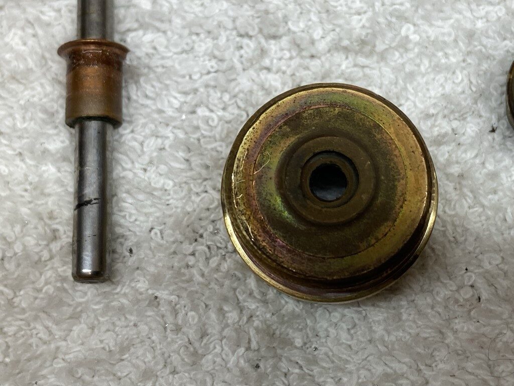
Starting at the bottom of the insert, this is in contact with the central heating water, the first part is the plunger which has a disk of rubber, copper riveted to it, this forms the watertight seal when the plunger is pushed fully down into the seat of the valve body.
The plunger is pushed tightly onto a stainless steel pin allowing the pin to raise and lower the plunger, the pin passes through a rubber seal in the body of the brass insert.
With the pin in the body, a spring sits over the pin and a copper ferrule holds the spring in place.
The last part is the stainless steel collet which is held in place by a ribbed design, locking into the brass body when pushed in.
The action of locking the collet in to the body, compresses the spring, forcing the copper ferrule to seat against the underside of the collet and lifting the pin to the correct height to enable the plunger to be lifted clear of the valve body seat.
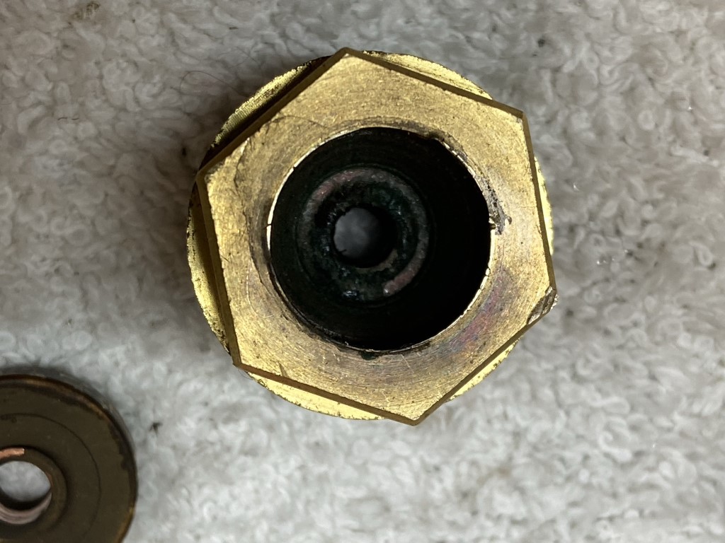
Where are the problem areas?
The majority of my problems were due to the pin sticking, the root cause is where the pin passes through the rubber seal at the base of the brass insert body, and no amount of lubrication will get anywhere near it.
It looks like the rubber seals have age hardened due to being subject to wide temperature variations over time, eventually the seals friction against the pin overcomes the springs lifting force.
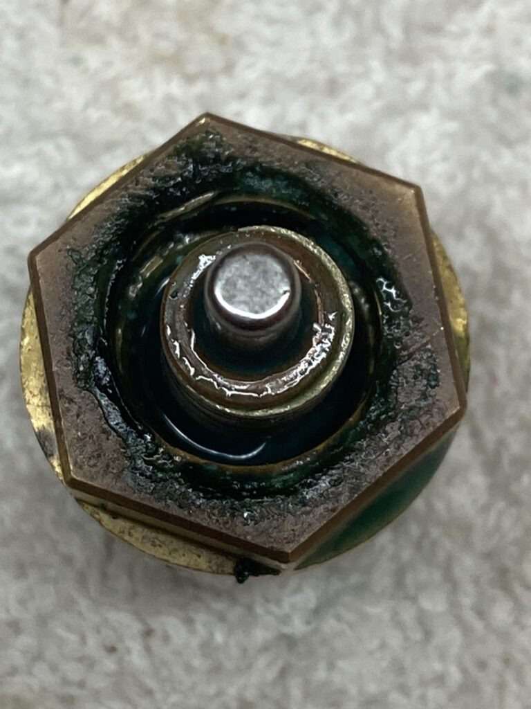
Obvious sign of water seepage into the insert cavity.
As a result of the pin seal ageing, system water creeps into the insert cavity, making its way past the locking joint of the collet/body or collet/pin, manifesting as discolored caking at the interface, this is an area for ‘weeping’ as the gunge is damp and therefore a point where system pressure is lost.
This picture says it all, the top insert shows how a good one should look, with the pin freely moving when pressed down using an upturned spoon.
To Sum Up
Don’t waste your time lubricating or tapping TRV pins like I did, the pin is sticking at the seal and no amount of lubricant will fix it 🙁 .
If the pin sticks or gunge is evident, you are only putting off the inevitable valve change, a plumber can do what I did a lot quicker and in some cases without draining the system, however, it is a DIY job if your confident.
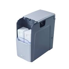
Being a new water softener user, (March 2021), I was constantly checking the level of the block salt my Kinetico Premier Compact uses and as my unit is outside due to space restrictions, I thought there must be away to remotely alert if more salt was required.
Final Version (23 February 2022)
Below you will find a number of different versions and iterations of my attempt at alerting to low salt level in the water softener, this is what I have ended up with.
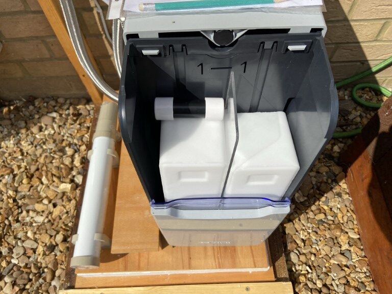
No additional devider required to keep the salt blocks apart in the softener, this caused the salt block to jam 🙁
The Sonoff wireless contact was simply out of range of wifi reception no matter what I did, this caused it to intermittently drop offline and eat batteries, so this was removed.
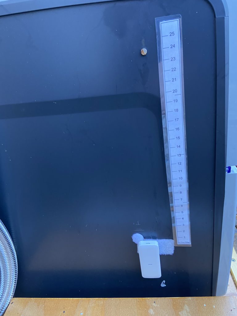
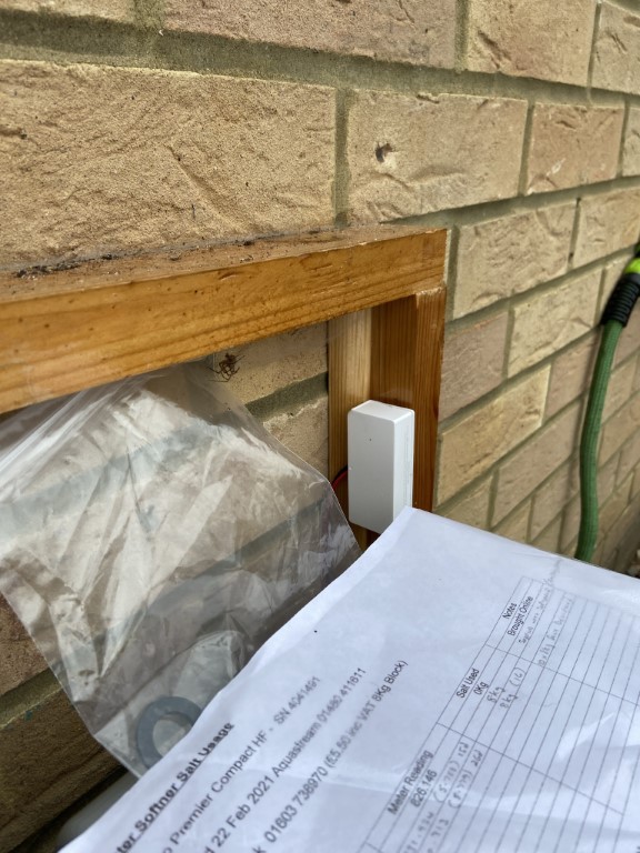
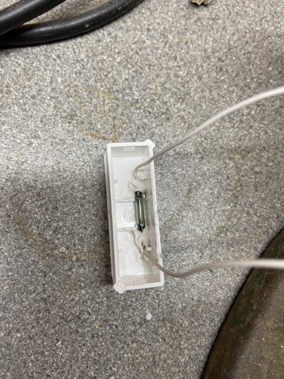
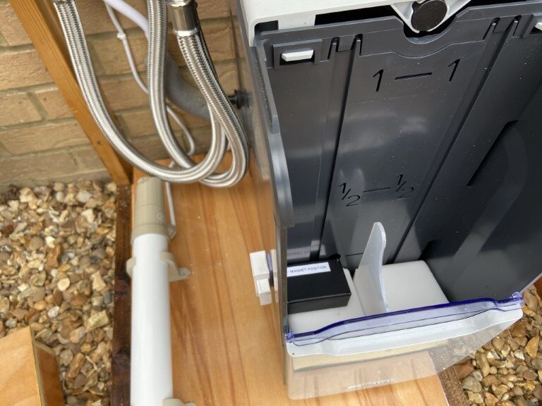
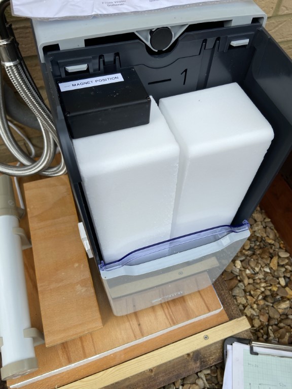
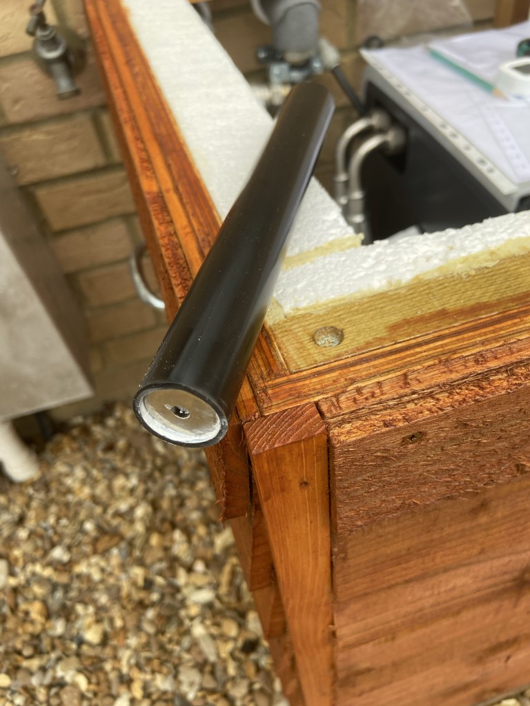
Replaced the Sonoff with a Pyronix Nano door contact:
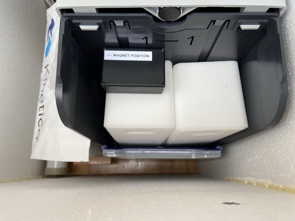
The magnet carrier within the softener remained the same, simply resting on top of one of the blocks and the Nano contact velcroed on the side of the casing, in the same place where the Sonoff used to be.
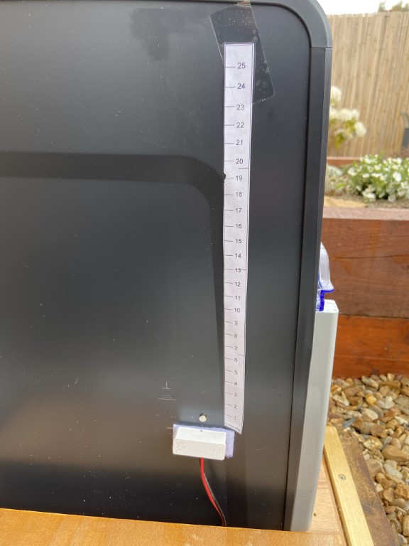
A little circular magnet gives me a level indication of the salt block, average usage is about 11mm of salt block erosion per day.
The Nano contact links into the house alarm system and is configured to log events and act as a simple switch to operate a relay when the contact opens or closes, this is a totally independent function of the alarm and will not cause an alarm activation if the salt goes low 🙂
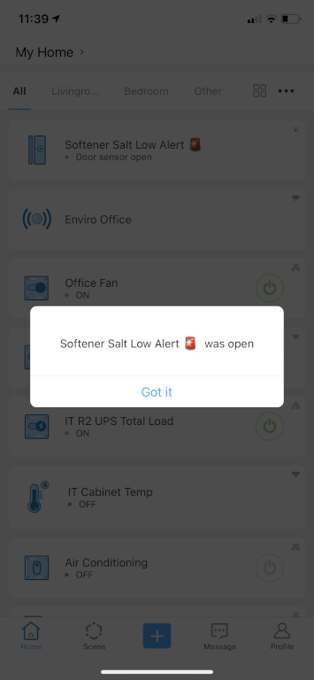
I have brought the Sonoff switch inside and it is now triggered by the relay which changes state based on the Nano, this allows a ‘Scene’ to run, switching on and off a mains lit sign when the salt is low as well as an App notification.
The use of using an intruder alarm contact is that communications between the contact and the alarm is monitored as is the battery condition, giving me a failure alert which I didn’t have with Sonoff.
This setup has been in use for about two months and has worked really well, I think this may be the last time I have to play with it!
Version 4 (21 May 21):
I have used Sonoff Smart devices for a number of years which are monitored and controlled via the eWeLink App on my iphone and ipad so I knew this was the non invasive way to go, especially as the DW2 battery level and online status is monitored and alerted on the App .
Caution – The method I’m using is not fail safe, please don’t blame me if your water reverts back to being hard because you ran out of salt :-).
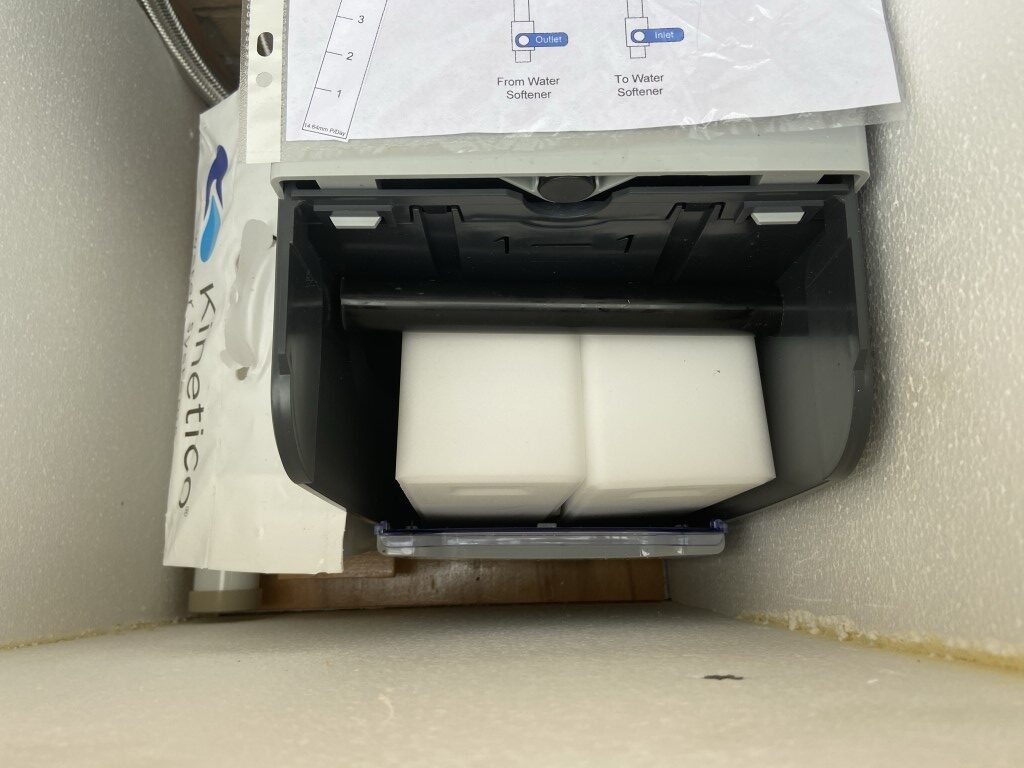
The idea is that a strong magnet will be carried on top of the left hand salt block as this was observed to be slightly lagging the right hand one as the blocks dissolve.
The magnet will be lowered by the dissolving salt until a point is reached which it will trigger the Sonoff sensor which will be attached to the outside of the water softener, this will then trigger an alert via WiFi and the eWeLink mobile App as below.
A 90mm length of 25mm PVC tube with sealing end caps sits on the salt block, inside the left hand cap is a 20mm x 4mm disc Neodymium magnet. To enable the magnet to be guided throughout its travel, a Perspex divider is used between the two blocks.
On the outside of the softener the Sonoff switch is fixed with Velcro at a height which will give me a few days notice of low salt, with the wires from the switch have been extended to the Sonoff transmitter, and this is now mounted as high as I could get it within the enclosure in an attempt to get the best WiFi signal.
I also decided to use a smaller magnet on the outside of the softener to show the position of the salt block magnet, a graduated strip shows approximate days salt usage left (26 days per 8Kg).
The level detectors signal strength is quite good and seems to work, but its still early days and more monitoring is needed before I can say with certainty that it can be relied upon fully.
On thing to App allows you to do is link to other devices in the Sonoff range, I have set a ‘scene’ so that on low salt detection, a mains powered light will turn on in the house giving me a visual indication, which is a great feature.
Testing of the Sonoff is very easy, I simply place an external magnet near the device to confirm operation.
NOTE: Most of the difficulties in my installation have been with WiFi signal, if your softener is indoors, an unmodified DW2 with a magnet in a tube would work just fine 🙂
Sonoff Devices
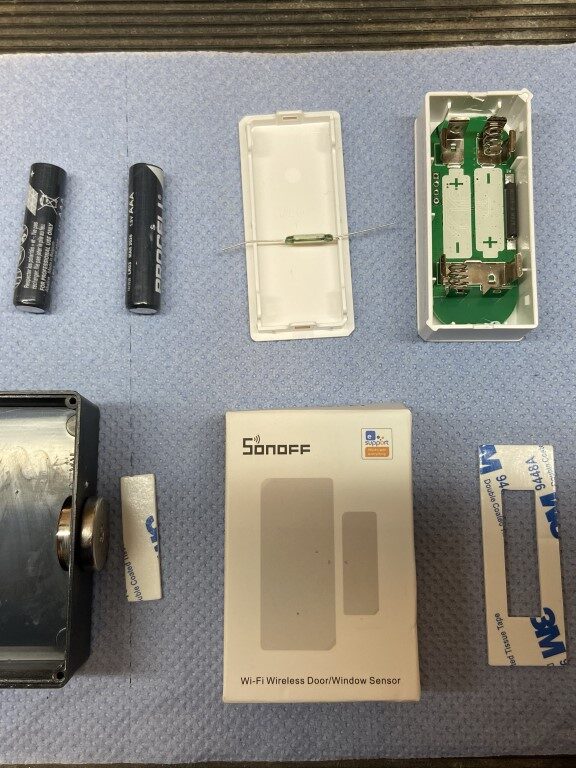
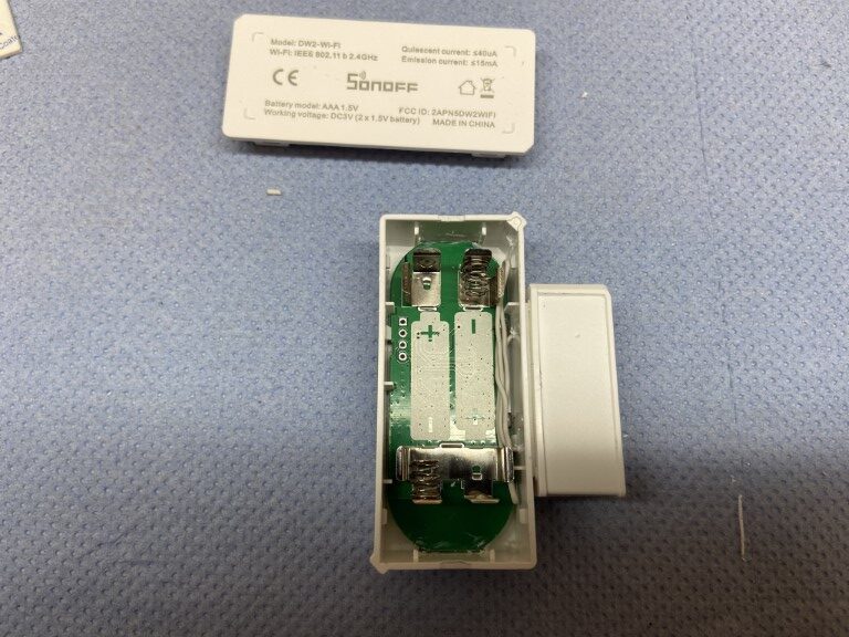
The WiFi sensor I used was the battery operated stand-alone Sonoff DW2 -WiFi wireless Door/Window Sensor, as I already had a number of Sonoff devices and the eWeLink App on my iphone.
I did modify the sensor as described further on, but I didn’t have too, as the App had a selectable setting to push notify when the sensor either goes Closed or Open, equating to ‘seeing a magnet’ or ‘not seeing a magnet’ which if I’d known first I wouldn’t have gone to the effort of taking it apart :-).
A key takeaway is that the Sonoff must be in range of your WiFi, obvious I know, but it caught me out!
How it evolved to the working version
The Sonoff modification would be to change the original Reed Switch which is normally kept closed and out of an alert condition by the presence of a magnet, I needed the opposite of this, the introduction of a magnet would cause an alert, (as mentioned earlier, this really doesn’t matters as the App settings could have solved this).
So to the shopping list, all of eBay:
Version 1
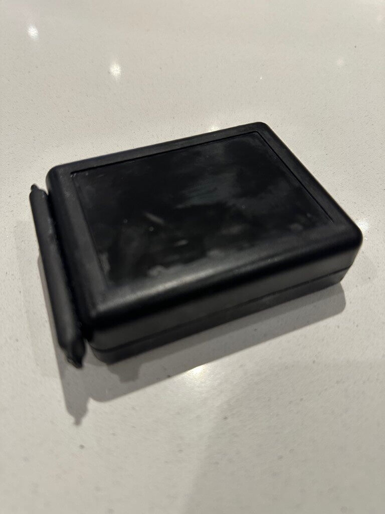
ABS Box (75.5 x 49.5 x 28) @ £4.50,
Disk ring Neodymium magnet 20 x 4mm @ £4.89 for two,
Reed Switch 3 pin magnetic switch normally open closed conversion 2.5 x 14mm @ £4.79 for five,
(Version 2) offcut of 22mm and 20mm plastic conduit (already had).
Parts came to ~£23.00
Version 1 – First job was to glue the disc magnet inside the ABS box, after trail and error, the best place for the magnet was the rear left side of the box.
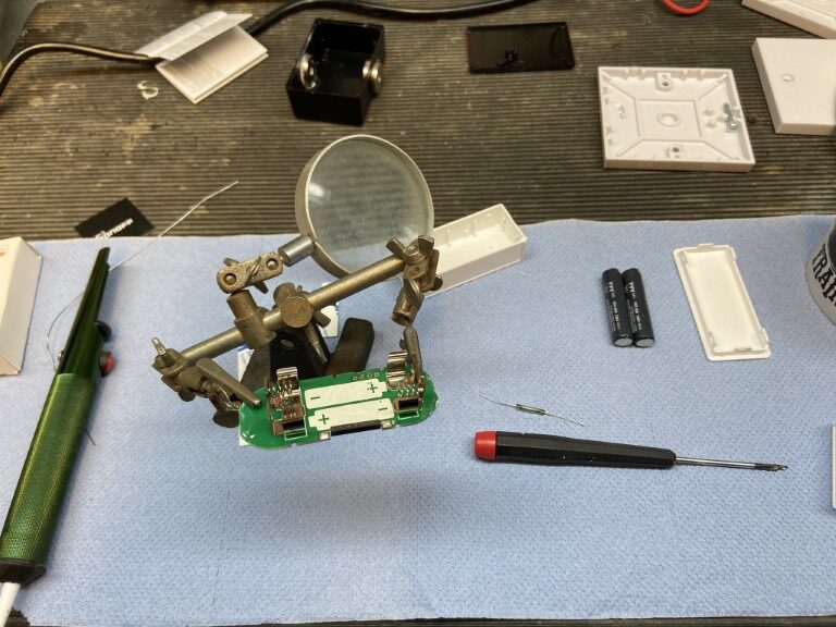
Next task was to remove the reed switch which comes with the DW2, this is easily identified as the long thin black rectangular component on the same side as the battery clips, this simply unsolders from the PCB pads.
The PCB is held in place by a small blob of white silicon at each end and a clip, using a small screwdriver to carefully prise the board out does the trick.
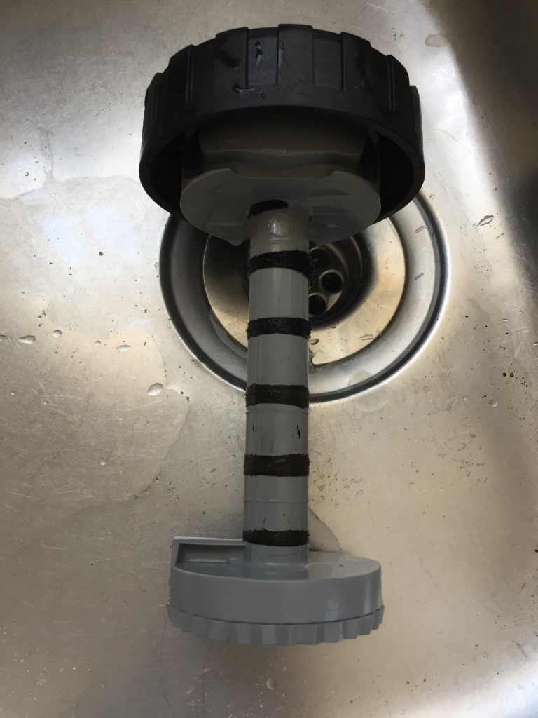
I originally soldered the normally closed reed switch in the same places as the original, but I thought I needed to get the reed switch as close as I could to the wall of the softener, so I used the Sonoff’s magnet enclosure to hold the normally closed reed switch after attaching so flying leads.
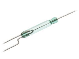
The image below shows the type of reed switch I needed to fit as I had to change the reed to be normally closed without the presence of a magnet, telling the DW2 door sensor that the door was closed, when a magnet is introduced, the reed moves position within the glass envelope, breaking the circuit, triggering the DW2 to alert to a door open which in our case is low salt level.
A couple of holes were drilled and the wires from the reed switch were soldered to the PCB pads.
Once the eWeLink App is downloaded and an account is created (can be free but I chose to pay the nominal fee), the DW2 can be paired on the 2.4GHz WiFi home network, this is incredibly easy, open the app, press and hold for 5 seconds the push switch on the DW2 until a red LED flashes, back on the App – Press add device and after entering your WiFi details, the DW2 is paired 🙂
Details can be configured in the App, including changing the alert description, push notification and sharing the alerts with other eWeLink accounts if needed.
Now the moment of truth – bringing the magnet close to the reed switch should trigger the App status to show the switch is open and change to closed when the magnet is moved away.
As my block salt level was low, I noticed that the blocks tilts back slightly in use, I put the ABS box on top of the left hand block and due to the lean it should stay in the same place on the block as it drops.
I offered up the DW2 to the outside of the softener while watching the App status, moving it up and down the outside of the unit until it triggered, I marked with a pencil using the top of the DW2 on the cabinet the point at which I wanted an alert, I then stuck a strip of self adhesive Velco hoops under the pencil line.
The magnet I used is deliberately powerful, and it was no surprise that it operated the reed switch when it was some distance away from the reed switch and will continue to hold the reed switch open for a fair bit of travel as the salt level lowers, this was factored during the setup process.
Using Velco I secured the DW2 to the softener as this allows for fine adjustments and the job is done.
Salt changed and system ready with room for the lid.
This was the first time I had replaced the blocks and those with keen eyesight will note the blocks are not installed as per the manual (page 18), this has now been rectified.
Version 2 – Magnet Carrier
A few days after changing the block salt, I decided to see how the ABS box magnet carrier was sitting on top of the salt …………disaster!
As you can see from the picture, the left hand salt block has leaned over to the right taking the magnet too far away from the side wall, it may well be that when the salt block drops it may once again move to the optimal position for the magnet, I didn’t want to take the chance, so here is Version 2 which will defiantly need further revisions.
I took the two magnets out of the ABS box and cut two pieces of plastic conduit, the 25mm conduit spans the salt block gap, with a shorter piece of 20mm conduit glued inside it, the magnet was glued inside the 25mm pipe with the 20mm pipe acting as a backstop.
It was important that the magnet was flush with the end of the pipe as I’ve ordered some plastic end caps as I don’t want any metal contact with the salt or brine solution.
Its quite hard to see, but the conduit pipe bridges both salt blocks, I put a magnet at each end so it wasn’t important which way round I put it in.
The major problem with this design is that the pipe will hit the salt grid which I have only just noticed, so watch this space!
Version 3
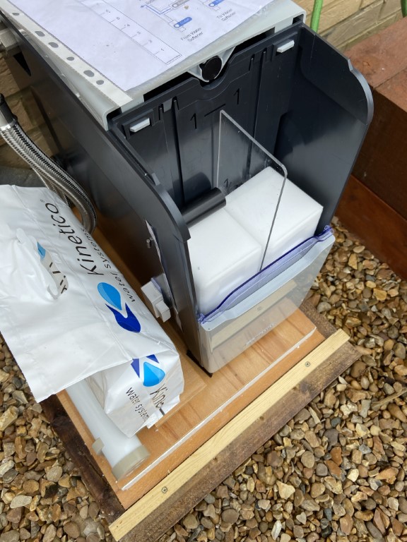
To address the problems with Version 2, I bought a piece of 3mm thick Perspex and cut it to act as a full height guide for the left and salt block, the guide simply rests against the salt and the existing salt grid assembly.
I cutdown the magnet tube holder to be a nice fit and this time I’m only using one magnet to bias rather than trying to balance the tube.
Lessons Identified
1 . Make sure you have a solid WiFi signal where the DW2 is fitted.
The eWeLink App shows signal strength that the DW2 is seeing, however, once I put the box around the softener, the received signal strength fell and the DW2 went offline. To resolve this I changed one of the kitchen sockets, which is near to the softener, to a WiFi extending version from Screwfix (988FV) and this worked fine.
2 . The DW2 eWeLink allows for a selectable Push Notification to your phone if the switch either opens or closes, I could have left the DW2 as it arrived out of the box and made the change in the App rather than physically modify the DW2.
3 . My salt level was falling at a rate of 14.6mm per day and we will always have 8Kg available (Block 280mm tall/14.6mm daily usage = 19 days per 8Kg). This was the first salt the softener had used, so it may slow down, the point being to set the alert level to suit adding a new block straight away, or as a trigger to re-order or change it in X days, the positioning of the DW2 determines the alert trigger.
You could always add another DW2 using the same magnet, with one DW2 set as a pre-salt order trigger with the other DW2 as the block change alert.
4 . The ABS box for the magnet was just the right size, if it was any larger it might not allow the lid to close in the salt compartment when a new block was fitted, but it was small enough to give me an alert on low salt level with 30mm salt left (day and halfs worth).
5 . Keep an eye on things in case they don’t go to plan, hence Version 2 🙂
Ricks TwinTec Softener Alert
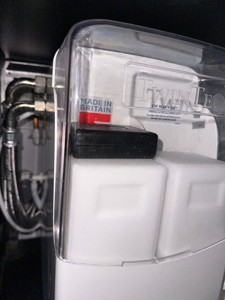
Rick got in touch as he has a TwinTec water softener and was looking to also have a low salt alert and sent me a list of parts he was going to use and his ideas:
Ricks design was for the magnet which triggers the wireless door sensor to mounted on the outside of a waterproof box which sits onto of one of the salt blocks, the external magnet will also space the box away from the side wall, the wireless sensor will be affixed to the outside of the softener.
The final location of the sensors exact position will be by ‘test & adjust’, making sure it triggers when the salt level is at the right point that it needs replacing.
With the aid of a Zigbee repeater (Hubitat C8), when the sensor triggers an alert is set to Ricks phone and Alexa speakers announce out loud ” replace salt in water softener“, but so as not to wake everybody, Rick has set the announcement to stay quite between 10pm and 9am.
Really pleased it works for him and a great project, so thanks for allowing me to share it.
We moved from the North a number of years ago from a soft water area to Chatteris, Cambridgeshire which has water classified as Hard, the effect of this is that soap doesn’t lather easily and appliance heating elements get coated in limescale reducing efficiency and life.
As a home improvement project, I decided to research water softeners.
How is Hard Water Quantified
Parts Per Million (ppm)
This scale is used to measure very small amounts of something in a larger quantity of liquid. It is used to measure dilute concentrations of chemical substances. One litre of water weight 1 million milligrams (mg). So 1 part per million (ppm) would mean the chemical is one millionth of the solution, or 1mg per litre.
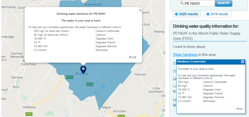
For water hardness levels, we measure parts per million of minerals including calcium carbonate (CACO3) in the water. Calcium carbonate is the compound in hard water that causes limescale build-up. Soft water typically has less than 50 ppm of calcium carbonate. Hard water has over 200ppm, Anglia Water drinking water quality information for the Chatteris area shows that the level is 230ppm compared to where we used to live which was 17.5ppm.
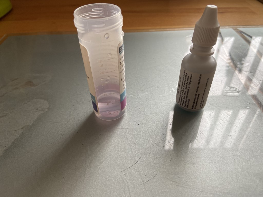
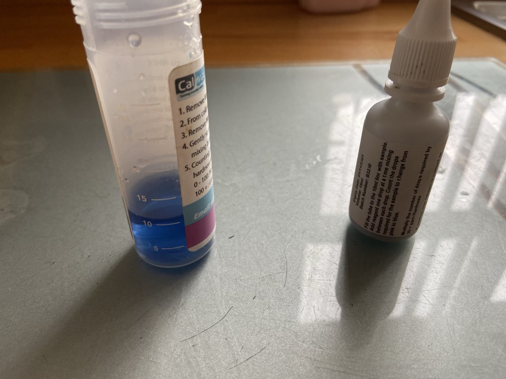
I bought a water hardness test kit from Toolstation and this indicated that my incoming cold water was between 240ppm ~ 280ppm so I know the extent of the hardness which be of use later.
1 drop of reagent into incoming hard water , adding drops until the solution turns blue
After 12 drops equates to 240ppm on the 1 April 21, the same test on the 22 February 21 came out at 280ppm.
These work by ion exchange, incoming hard water passes through a bed of activated resin beads, these beads remove the calcium carbonate and magnesium molecules as the water passes through the resin chamber, the exiting water is now free of the limescale causing molecules and is now soft.
To maintain the resins ability to ion exchange the resin is backflushed with a brine solution, the backflush waste water goes directly to drain.
There are a number of considerations to take into account in selecting a water softener, these are:
Cost to purchase
Cost to run
Salt – Block or Granular
Number of bathrooms
Number of people living in the property
Incoming water pressure
Single or Two resin chambers
Type of hot water system (Gravity, Indirect or combi boiler)
Electrical supply required or not
Physical size of the softener and where will it go
Warranty
Dealers
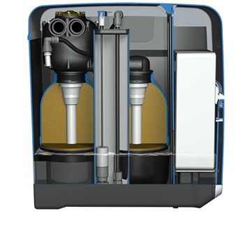
Cut away view of of Kinetico premier compact
What did we choose and why
I’m definitely no expert on water softeners, first port of call was the internet and YouTube to see what were the popular UK models and to read reviews that users made on dealer sites.
Going through the above list, the purchase and running cost will be known after most of the other points are answered.
3 live in the property and we have 2 bathrooms (ensuite shower is classed as a bathroom), the hot water is supplied from an unvented indirect cylinder, meaning the hot water is under a constant pressure and pushed out of the cylinder to the hot tap by the incoming water pressure at the bottom of the cylinder, the incoming pressure is typically maintained at 3 bar so that the hot & cold taps and mixer showers for example are at the same pressure.
Where the hot water uses the incoming water pressure, a High Flow (HF) unit will be required as the flow rate is higher through the resin chambers to reduce any pressure drops, also the softener inlet and outlet pipes are larger.
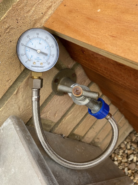
If the water pressure to the house was low, introducing the water softener might cause a problem, I measured the pressure here at 2.8 bar (40psi) which is fine, a pressure gauge is available from Toolstation.
The activated resin chamber I mentioned earlier needs to be regenerated, (back flushing the beads with brine (salt solution)), with a single chamber, softened water will not be available during the regeneration process, we opted for a dual chamber unit so we always have a supply of softened water, however this does have a cost implication.
How does the softener know it needs to be regenerated?
Two methods, timed or metered. With a timed version, an electrically powered (low voltage via a transformer) timer will trigger the process, the main disadvantage apart from requiring a power source is that regeneration could occur if no softened water was used, but simply based on time.
A strong advantage of an electrically powered softener is the ability to have an alarm indication on low salt, with a mechanical only unit, you have to physically monitor this (but I’m working on it 🙂).
The softener we selected used actual metered soft water usage to mechanically trigger regeneration
The model which satisfied all our requirements including a 10 year warranty was the Kinetico Premier Compact HF which we bought from Aquastream Water Softeners Ltd who gave exceptional service, they responded to my emails quickly and are experts in their field, I would not hesitate in highly recommending them.
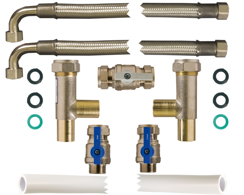
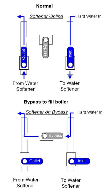
If you are a confident at DIY, the plumbing for the water softener is very easy, with only two pipes and a drain hose, the price of the softener included the 22mm Bypass kit which contains all the full bore valves, strainers and 0.75m flexible hoses to connect the houses fixed plumbing to the softener.
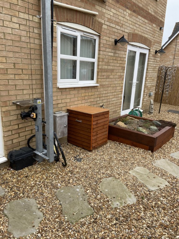
Due to the underneath of the kitchen sink base unit being full of other stuff, we decided to put the unit outside and to build a wooden insulated enclosure for it.
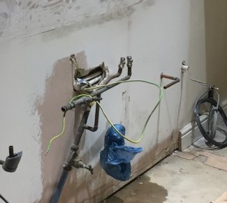
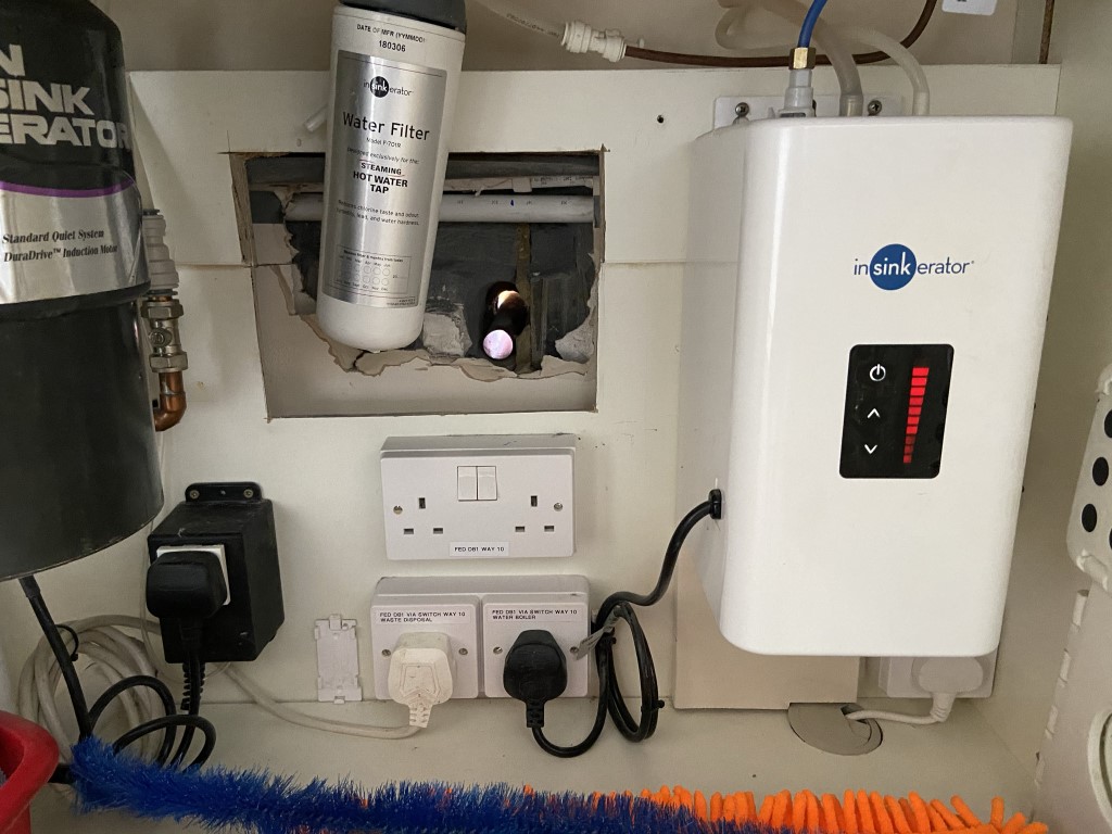
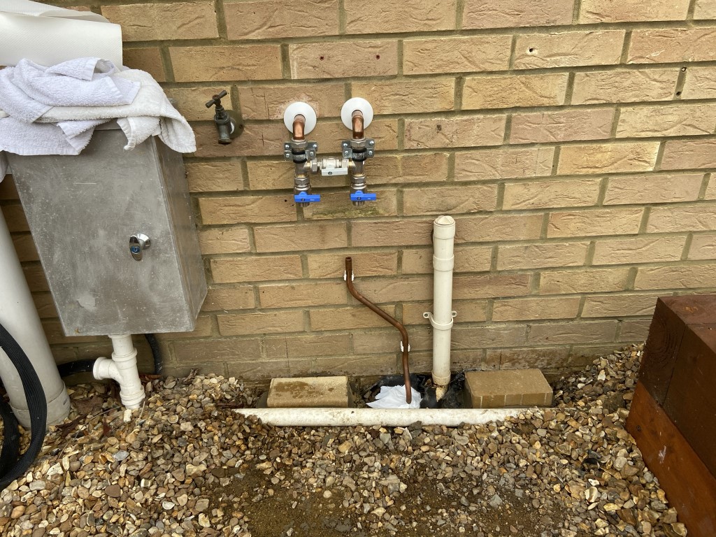
As we replaced the kitchen a few years ago, I knew where the incoming water pipes run, from the picture below you can see the rising main and stop cock, this tees off for the kitchen sink, with the 22mm copper pipe transitioning to John Guest 22mm push fit disappearing behind the dot & dab plaster boarded wall on its way to upstairs.
The kitchen base cabinets were a bit too ‘busy’ for the softener to fit but left enough room for me to access the buried pipes once a hole is made in the cabinet back .
Once the cabinets back was cut out and plasterboard removed to expose the 22mm plastic cold water pipe, two 32mm holes were drilled to outside, the holes then sleeved with 28mm copper pipes ready for the 22mm copper passing through these to outside.
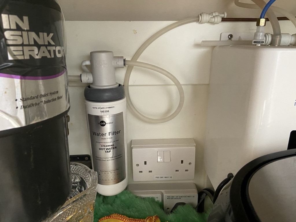
The water supply to the Insinkerator hot water boiler is from the valve on the left of the picture, the boiler water feed will be moved from hard to soft.
It is important to keep the kitchen sink cold tap feed before the water softener for cooking and untreated drinking water, it is also advisable to supply any outside taps before the softener to save on salt usage and prevent damage plants over time.
I used ‘O’ rings around the 22mm pipes to keep them centralized within the through wall sleeves.
To make the plastic pipe to fitting connection, it is important to cut plastic pipe to leave a clean cut and to use superseal pipe inserts, marking the depth of the fitting on the pipe before pushing it onto the pipe ensures that it is fully seated.
The pipe cutter I used came from Lidl and cost £5.99
On the John Guest pipe their are fitting engagement marks already made to assist with ensuring the fitting is fully pushed over the pipe, but my fittings didn’t marry up with these, so I measured and marked the pipe to confirm the elbow and Tee were fully engaged before pushing them home and tightening the collet ring after which I pushed on the locking rings (Blue clips).
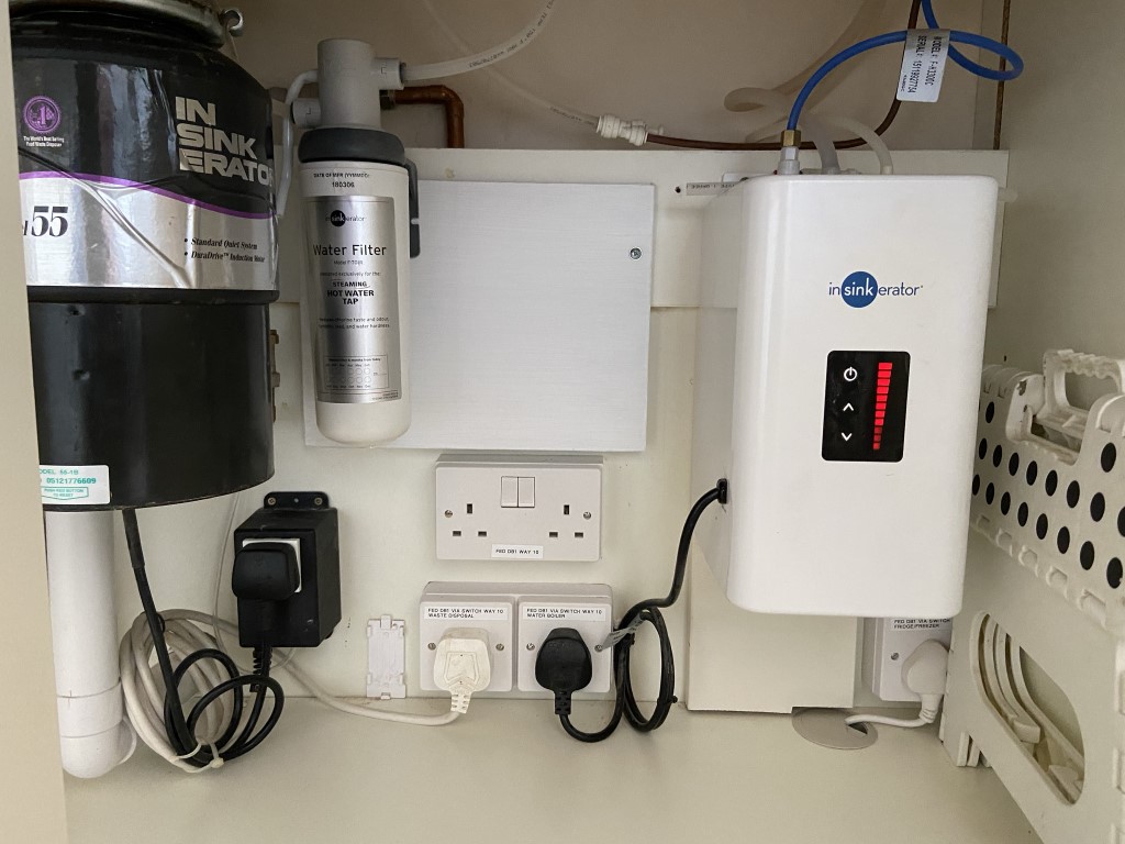
The 15mm copper pipe leaving the Tee in the picture below, is the new softened water supply to the hot water boiler, all the copper elbows (15mm for the water boiler and 22mm for the softener) are long street elbows, this reduces joints and saves space which was ideal in my situation.
To keep everything in place and to insulate the pipes I used expanding foam, two other pipes are in the picture, one is for the outside taps which I lagged internally when the kitchen was being fitted, the other is another plastic pipe, this time 15mm for the kitchen sinks hot water tap.
With the cover on, nobody would know the carnage 🙂
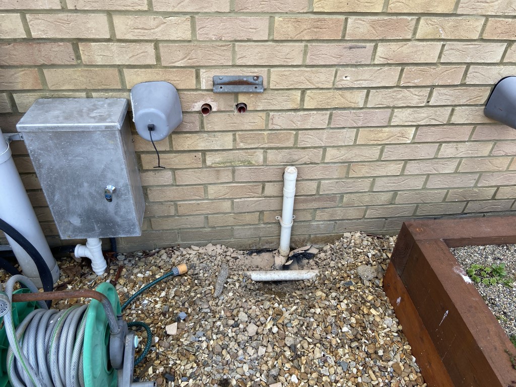
On the outside the bypass valves and copper runoff to drain installed.
The copper pipe is the regeneration drain for when the resin chambers are back flushed and must be air gapped from the waste system to avoid any cross contamination with the drinking water. The cold water inlet to the softener must have a a non return valve to prevent back flow.
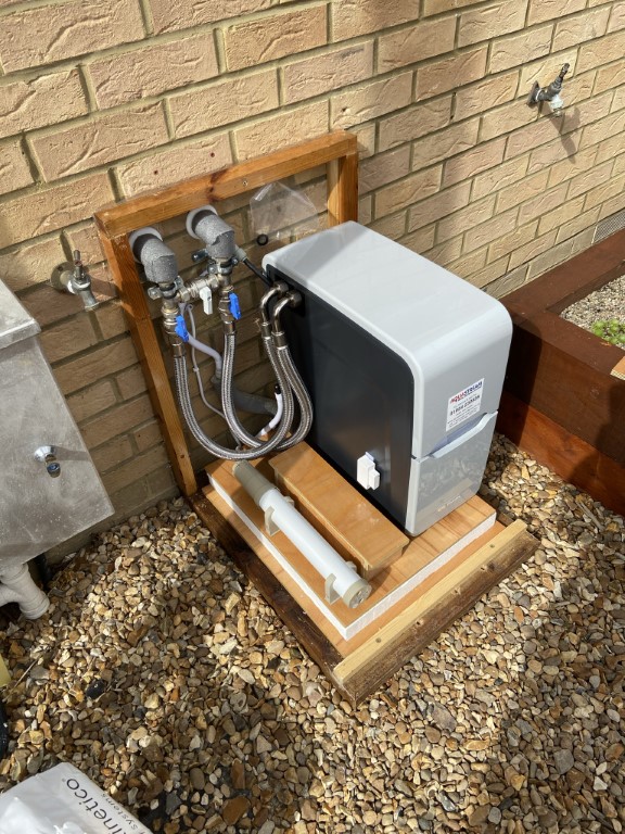
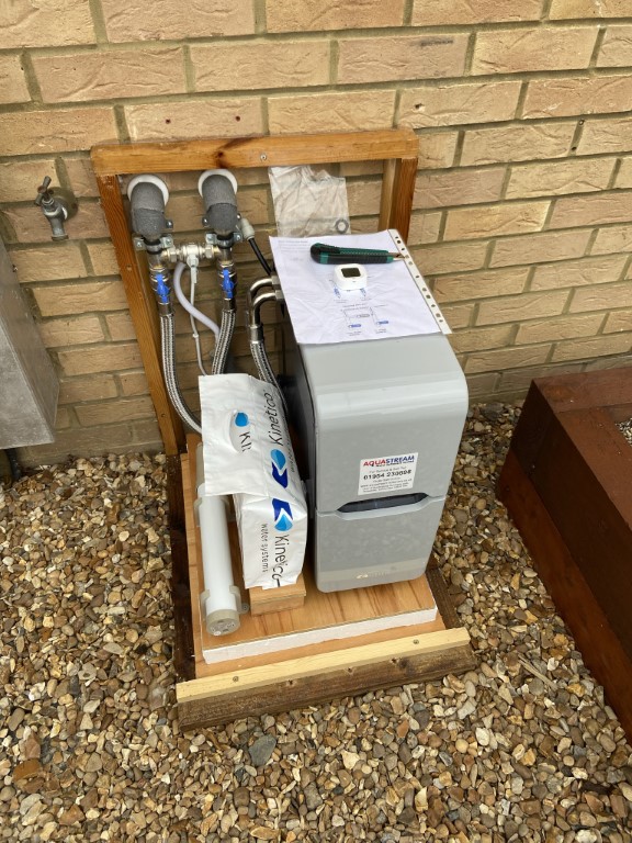
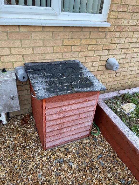
Finished installation, the Kinetico softener is off the ground sitting on a 50mm polystyrene backed base, 22mm stainless steel braided hoses each have a strainer fitted and to ensure that the softener doesn’t freeze, I have taken the precaution of installing a 40 Watt thermostatically controlled tube heater from Toolstation.
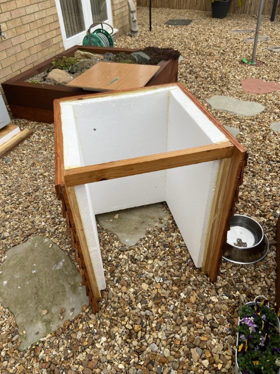
Easily removeable frame, sides and top lined with 50mm polystyrene, access for checking salt is by lifting the top off.
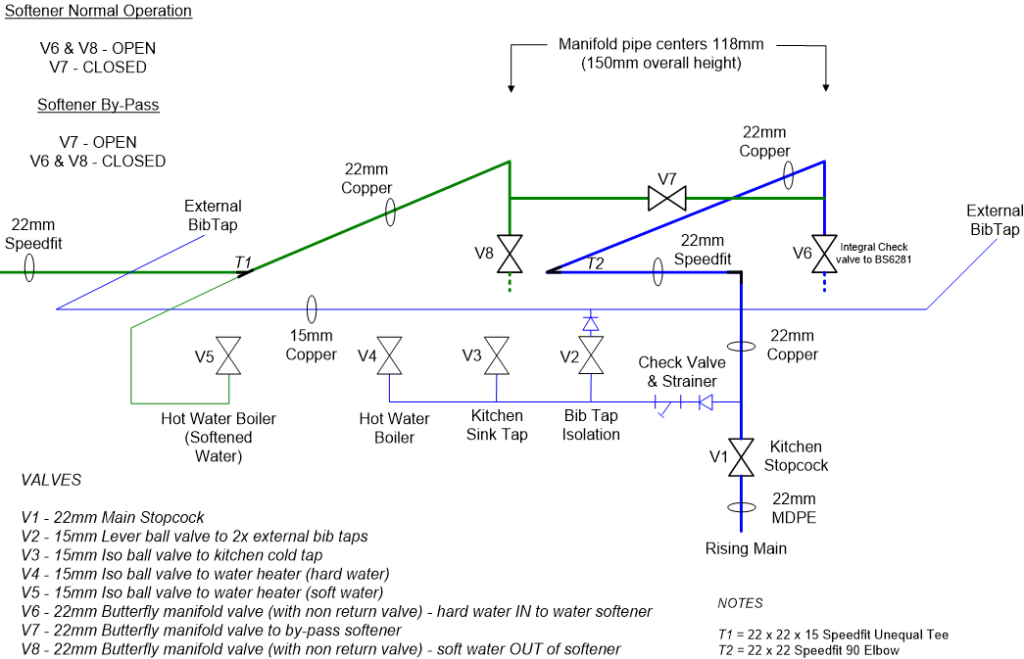
Pipe Schematic
Schematic for planning valves and documenting modifications
What are the Running Costs
The cost of the softener including bypass valve arrangement and 2 x 8Kg blocks of salt including factory setup was £1,295.00 inc VAT which was as cheap as I could find.
The only consumable other than regeneration water is Kinetico Block salt, the cost varies tremendously and I have found Saltstore to be the most competitive with an excellent online ordering system and friendly staff.
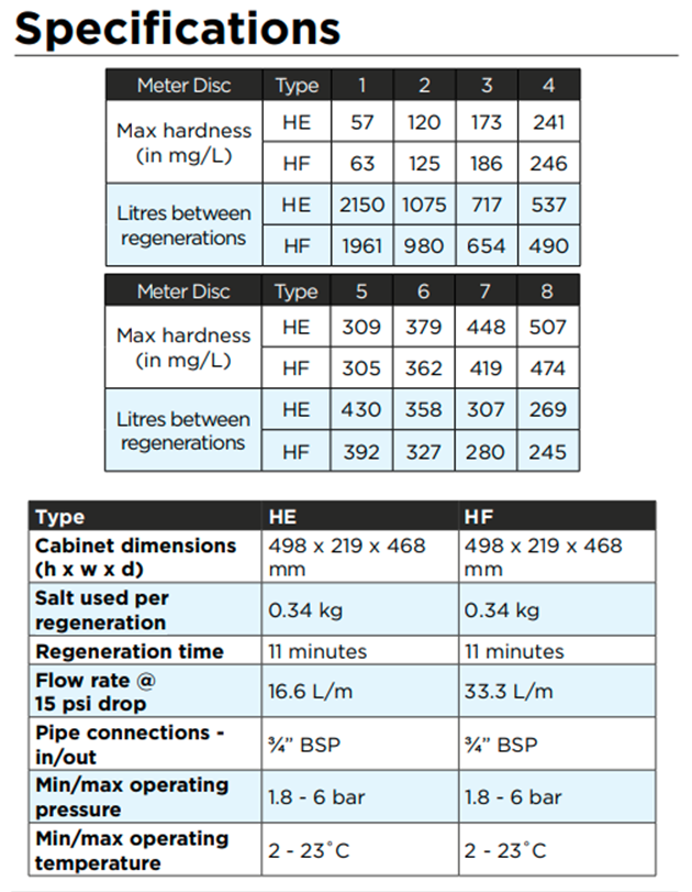
I have mentioned water hardness and the metered chamber regenerations, the Kinetico uses different metering disc types in their machines depending on water hardness, this directly impacts on the number of regenerations.
For my areas water hardness a Type 6 disc, which regulates regeneration frequency based on flow through the softener, is installed, therefore after 327 litres of softened water has passed through the resin bed, the cylinder will regenerate using 20.5 litres of water and 0.34Kg of salt.
After referring to the specification table, I did query with Aquastream Water Softeners the reason for supplying a Type 6 disk with my softener as this is for up to 362ppm and in my area the maximum I have measured was 280ppm which would be within the scope of a Type 5 disc (305ppm).
The answer was based on their experience and knowledge in that the table values are factory test bench conditions and not real world, the water in Chatteris is typically around 300ppm and very low flow through the softener would not be metered, therefore their is a risk that we could have hard water before the softener regenerated which made perfect sense. Good to know.
The following spreadsheet shows the actual 2021/2022 annual costs based on current usage:
Actual Running Costs
The cost of 8Kg of salt increased to £6 in 2022, the softener uses ~ 11.35mm of salt per day based on my usage circumstances, therefore, the cost of salt per year is £78.00.
For two years before the softener was installed, my annual usage was steady at199m3, after a year in use of the softener, my metered water usage has risen to 127m3, therefore, the water used in the ‘Regeneration Cycle’ was 8m3 costing £13.47.
The total running cost is £91.47 per year or 25p per day.
The softened water is fine to drink with no trace of a salty taste, soap lathers well with either hot or cold water, skin no longer feels dry and Barneys cocker spaniels coat is nice and silky now.
I need to remember to put the softener in bypass when I top up the central heating pressure, so I have a reminder drawing in the softener cabinet.
The softener has performed faultlessly, salt block usage is consistent, however, the price of salt has increased marginally, probably to reflect the increased cost of fuel.
Two observations since the installation have been:
I record and upload water meter readings every time I replenish the salt blocks and this led to the discovery that my water meter was failing due to the low recorded water usage, Anglian Water replaced the meter and the blog on that is HERE.
I have not monitored the effectiveness of the 40watt tubular heater in cold weather until now, and I’m happy that the wattage is more than sufficient to keep the water in the pipes from freezing.
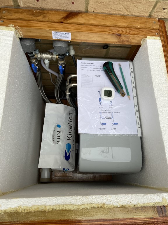
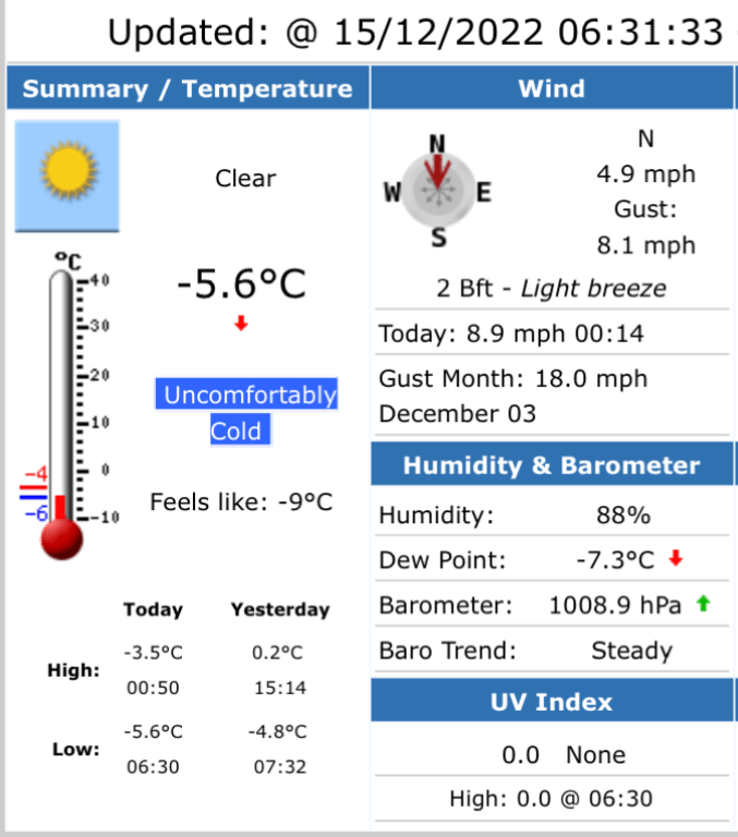
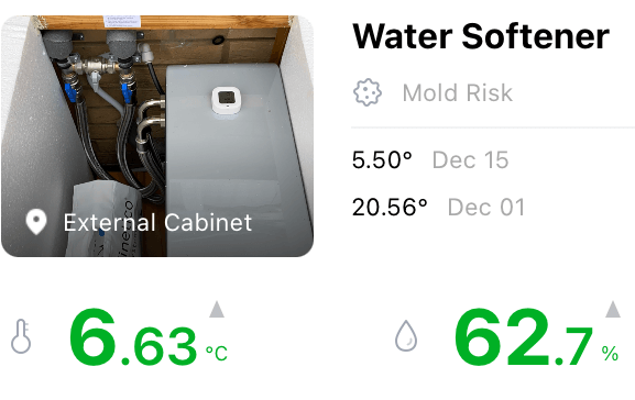
External water softener enclosure at -5.6oC, the internal 40W heater is ON and the picture shows where heat loss is occurring on the lid, internally the temperature is at +7.1oC, so all is good.
External temperature -5.6oC and has not got above freezing for a few days.
The ‘Sensor Blue’ within the softener cabinet shows a temperature of 7.10C indicating that the heater is working perfectly.
January 2025
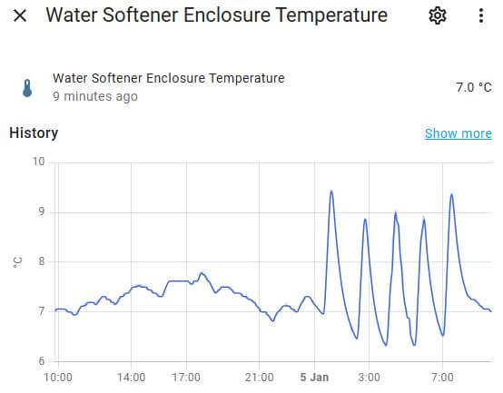
I now use Home Assistant to monitor the cabinets enclosure via an interface with the Sensor Blue temperature and humidity sensor, the graph shows the heater turns on at 6.4oC and off at a minimum of 8.4oC.
The outside temperature was below 4oC throughout, 4oC is the danger point for water as this is the temperature when water is most dense with the next stage being freezing.
February 2025 Update
I was at Stamford Garden Centre and noticed they had Monarch 8kg salt blocks which were the same physical dimensions of the Kinetico salt block for £4.99 which was a bargain, so I bought 10 and made a decent saving.
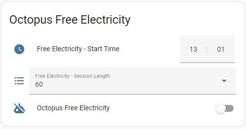
The reason for the update was to enable integration via the Tuya App with Home Assistant which will allow me to control the UFH when Octopus have periods of free energy.
Many thanks to ‘Speak to the Geek’ on YouTube for his video on this controller and how to create the Octopus Automation.
The replacement controller is the same dimensions and current switching capacity as the existing one and fits within the 35mm deep backbox, also I reused the existing floor buried temperature sensor which worked perfectly.
May 2019
I installed 150W/M electric underfloor heating in the kitchen and utility, each area was controlled using a separate TS700 programmable touch screen controller, these were bought off eBay for £20 each.
The TS700 worked fine but wasn’t very user friendly to programme and so you ended up not making any changes after the initial setup.
Looking for an alernative controller which will be within my buget and fit the same footprint as the TS700 and be Smart, I came across the BHT-002 series of WiFi enabled Thermostats on Aliexpress.com.
The Smart aspect means I can use an App (Beca Smart) to control and programme the controller, also as its App based, I can share permissions with familiy so they also can control the floor heating, another bonus is the ability to have control via Alexa.
The BHT-002 Series of controller has different versions, the one I selected was 240v AC and capable of switching 16A, it has a backlit display and WiFi connectivity.
Connection to the iPhone App was painless and the instructions an setup are considerably easier than the TS700, the cost from Aliexpress was £20 each, unfortunatly I had to pay £11.07 Customs Duty when they came into the UK, but they were a breeze to swop over from the TS700 and work perfectly.
A nice touch is the comfort light on the controller to show it is powered, all in all, a really good move to make the change.
The bedroom over the garage was always colder than the rest of the bedrooms, I decided to remove the existing single radiator and replace it with a Stelrad Compact K2 double radiator, this will give a heat output of 1645 Watts against the original radiators 907 Watts.
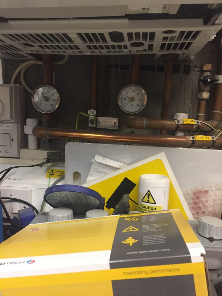
As the heating system needed to be drained down to enable me to make pipework modifications, I thought this would be a good time to add an air separator into the system.
My system already has two Automatic Air Vents, the difference with an air separator is that the heated water passes through a ‘packing’ which creates a turbulent water flow, any entrained air or micro bubbles are liberated, rising to the top of the device and vented.
The unit was very easy to install, the instructions contained a cutting gauge and the fitting location was ideal.
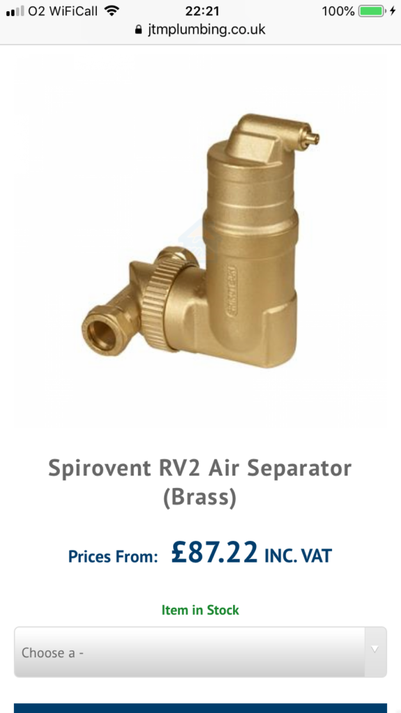
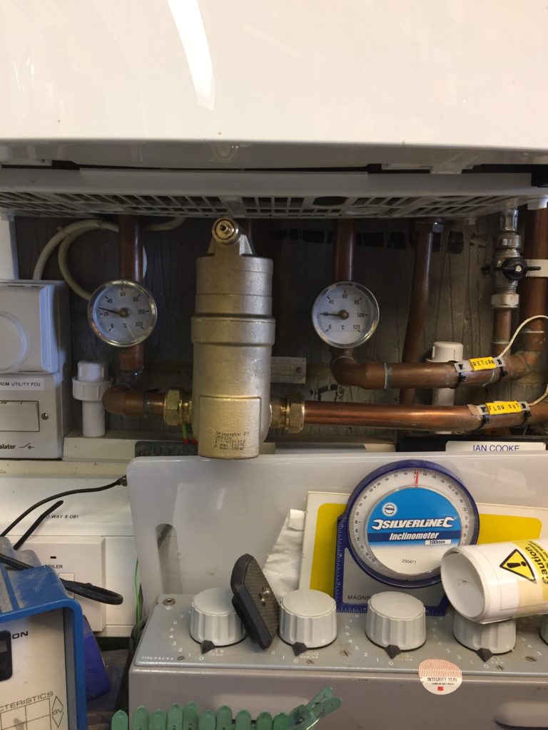
I had just enough room to install the Spirovent RV2 on the bottom pipe which is the flow from the boiler, the manufactures instructions suggest that the unit should be installed at the point where the heated exit water is the hottest, so this was ideal.
After the radiator was replaced and the Spirovent RV2 installed, I slowly used my filling loop via a pressure regulator to refill the system, checking for leaks and venting the system until all are had been removed and the pressure stabilised at 1.5 bar.
After the system had been running for a few days and all the air had been vented, I used the Magnaclean Pro 2 as a dosing pot, and replenished the Fernox F1, again after a few days I used the Fernox test kit to confirm that the inhibitors concentration was satisfactory.
On Youtube one of the respected UK plumbing engineer asserted that the circulating heating water should be treated more like a heat transfer medium and more effort should be paid to its treatment, going so far as to say that the customer shouldn’t top the system up with the filling loop, introducing aerated water. He has a point, but in reality this will never happen.
I currently have a Vaillant Thermocompact 624 System boiler which was installed in 2002 and some of the parts are now obsolete, so its only a matter of time before it needs replacement.
All new boilers now have to reach an ERP (Energy Related Product) minimum efficiency of 92.5% and only condensing boilers can achieve this, it does this by recovering the latent heat within the exhaust flue gases, this causes the water component of the flue gasses to condense and require disposal.
The boiler condensate produced varies in quantity and is acidic, therefore, only plastic parts can be used within the drain system (no copper or cast iron pipes unless the condensate has been neutralized first).
My existing boiler has no need for a condensate drain, however, when this packs in, any new boiler will.
I have read that if the condensate drains runs outside into a gully or soak-away, that the external pipe unless lagged or trace heated can freeze in the winter, and if the condensate can’t run away freely, the boiler will lockout until the pipe is thawed out.
Installation
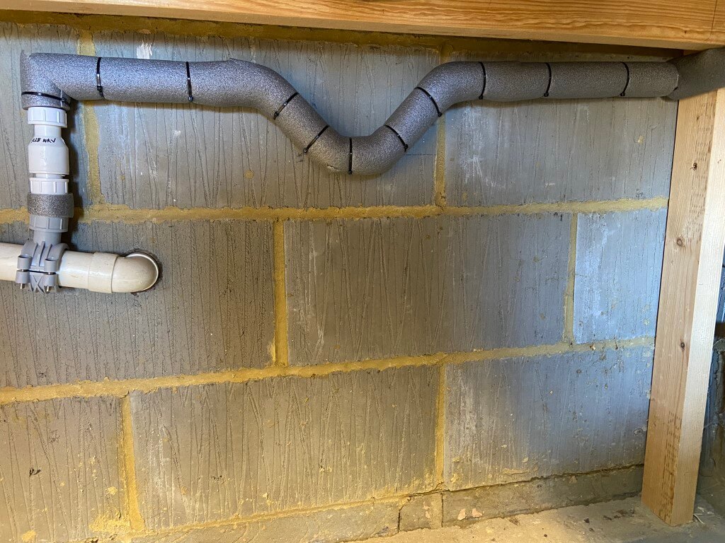
So, that’s the backstory, fortunately for me, the boiler is in the garage and also a portion of a 11/2″ (40mm) drain pipe runs inside the garage, before going through the wall to connect into the soil stack, the drain pipe carries the waste water from the washing machine, dishwasher and utility sink.
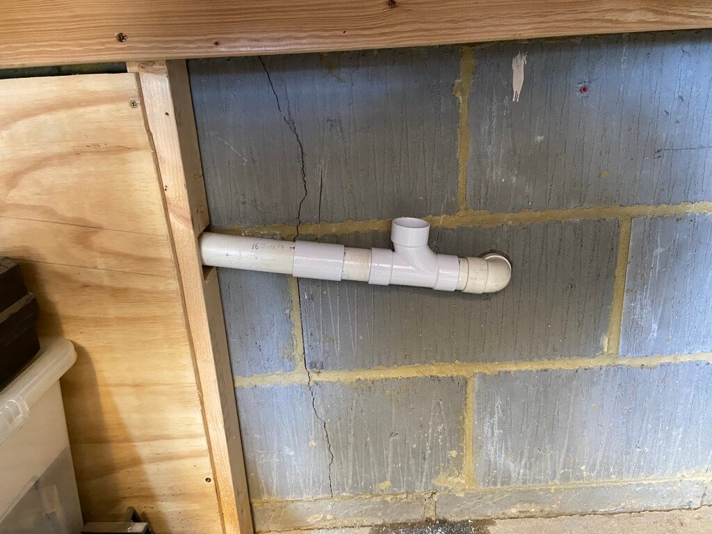
The pipe used was 22.5mm plastic overflow pipe from the boiler to the drain pipe clamp, the picture below shows the capped boiler condensate pipe in advance of the installation.
Fitting this pipe without taking the garage apart was a ‘challenge’ and took ages!
This pipe runs behind dado trunking where I used plastic cement to fix a 90 degree bend and ‘Tee’ with a capped stub so I can flush through if needed.
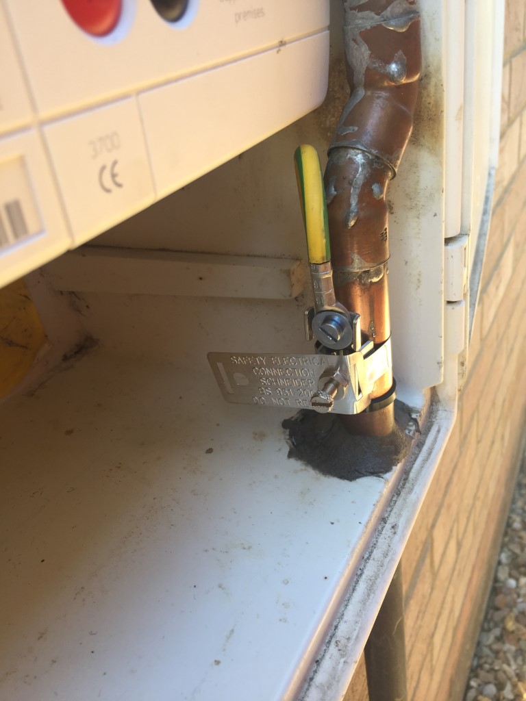
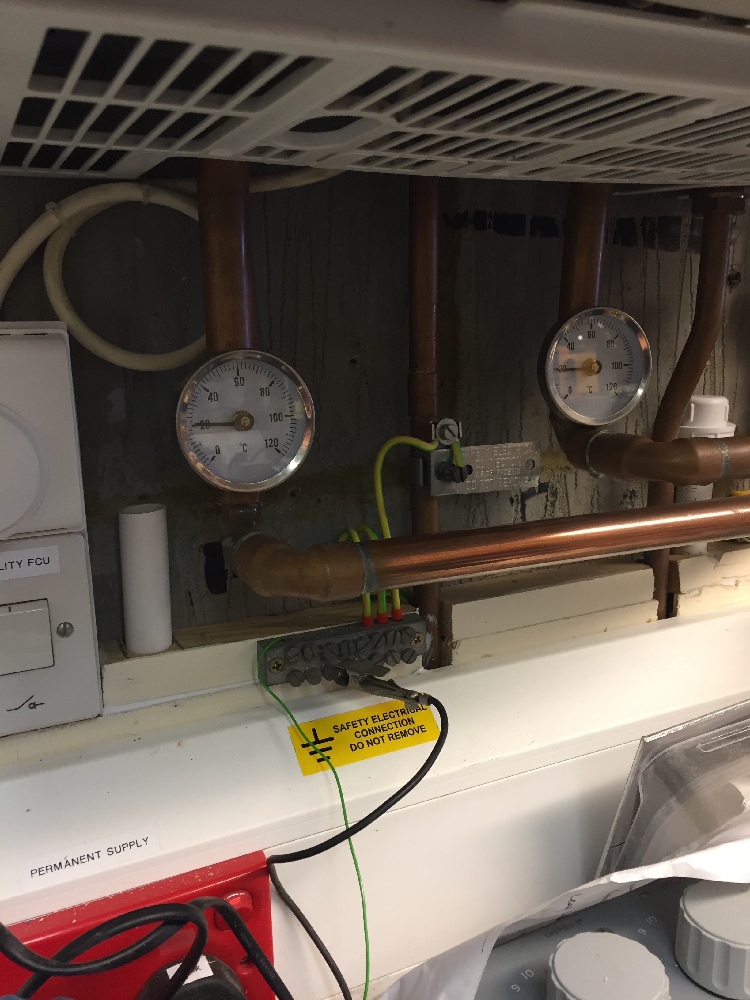
In this picture you can also see an earth clamp, this is fitted to the 15mm copper gas pipe and is the main bonding conductor for the gas, unfortunatly it does not comply to BS7671 Electrical Regulations, in so much as it is futher than 600mm from the point of entry and it is also installed after a branch, so I took the oppertunity to install a new clamp and 16mm2 main bonding conductor directly from the meters outgoing gas pipe to the consumer units earth bar, I could have used 10mm2 as I have a PME supply, but as I had the wire already, I made use of that.
After doing the first drain I rechecked the pipe layout on a Vaillant EcoTech and it showed the condensate oulet on the other side of the boiler, so it was out with the drill again and fit another drain.
This is the new gas main bonding conductor clamp fitted with the cable sealed after being routed of the enclosure, note the quality pipe soldering done by the British Gas Smartmeter man……Nice!
The additional uncapped drain below was a lot easier to fit as I removed the boilers isolator and frost stat to make more room.
The drain has to have a fall of 43mm per meter, the pipe was taken to a 90 degree bend and then on to the drain pipe, the pipe is supported every 300mm.
The picture shows a 75mm deep trap in the 22.5mm pipe, this then goes on to a McAlpine CONVALVE R28-NRV, this Non Return Valve will allow the flow from the boiler, but will restrict any back-flow from the drain pipe.
Installation of the NRV was very simple, I had to chisel the breeze block slightly so the clamp could fit without touching the wall, then drill a 15mm hole in the drain, debur the hole and fasten the 4 clamp screws and that’s it.
As the main drain pipe was at an angle and the condensate pipe came in vertically (the NRV will only work in this position), warming a small length of pipe and with an internal bending spring, I put a slight bend in the pipe, this was then cut to length and fitted between the pipe clamp and the NRV.
Once fully installed and all joints cemented, I ran a full bore water hose to check for leaks, once everything was checked, the exposed pipes were boxed in to stop any accidental damage (this pipe does form part of the boilers flue system when connected) and the garage was put back together again.
Not sure when my boiler will fail, but at least I’ve saved the plumber some time and effort and therefore I’ve saved some money in the long run.
Update
April 2023, Ideal Vouge Max 18kW system boiler ordered, checking on the guidance in Part L of the latest Building Regulations, there is now a requirement to insulate condensate pipes in unheated rooms, as my garage falls into this category, I have revised this blog.
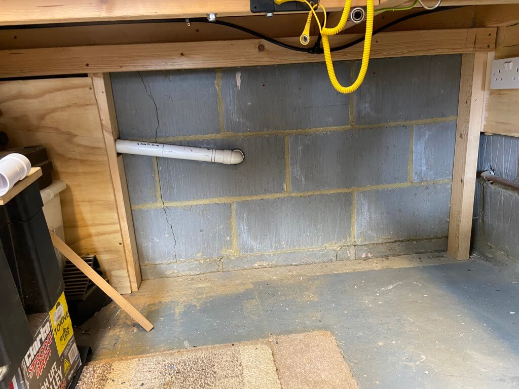
Rip out and start again
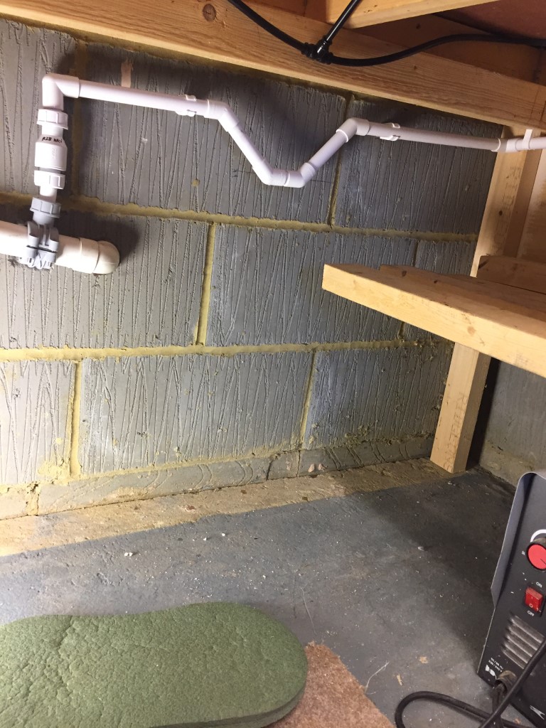
12 April 23, Gas Safe engineer came to cap off the gas to enable me to remove and install a new boiler, he noted the existing condensate pipe size and as the boiler is located installed within an integral garage, this is classed as an unheated space and as such the condensate pipe will need upgrading to 32mm and protected against freezing by Class ‘0’ waterproof insulation.
The pipe above is 40mm solvent weld waster pipe, so I decided to insert a 40mm Tee with a 40mm to 32mm reducer for the condensate.
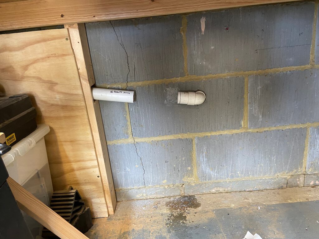
I had very little movement in the pipe as both ends were fixed, so I couldn’t simply cut the pipe and insert the Tee.
To get around the problem I filed the inner lip smooth of a 32mm coupling (socket), to make a slip coupling and cut the pipe, sliding the slip coupling onto the pipe, then fitting the Tee.
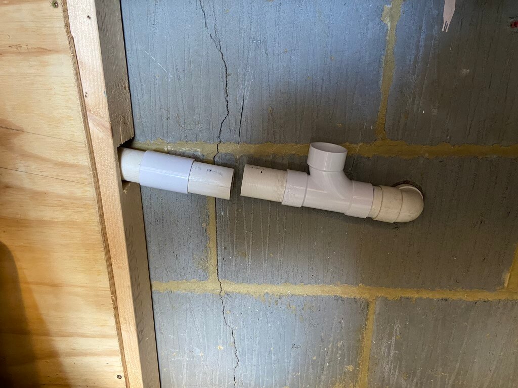
Solvent welding a stub of pipe in the Tee and then sliding the slip coupling back over the pipes to connect them after solvent welding.
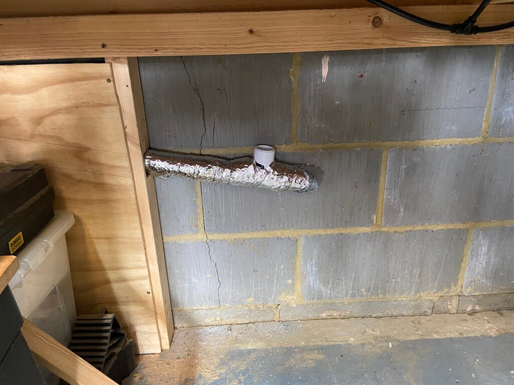
All done ready for lagging.
Lagged with 32mm reducer installed ready for the 135o degree bends to take the pipe to the boiler with the correct fall.
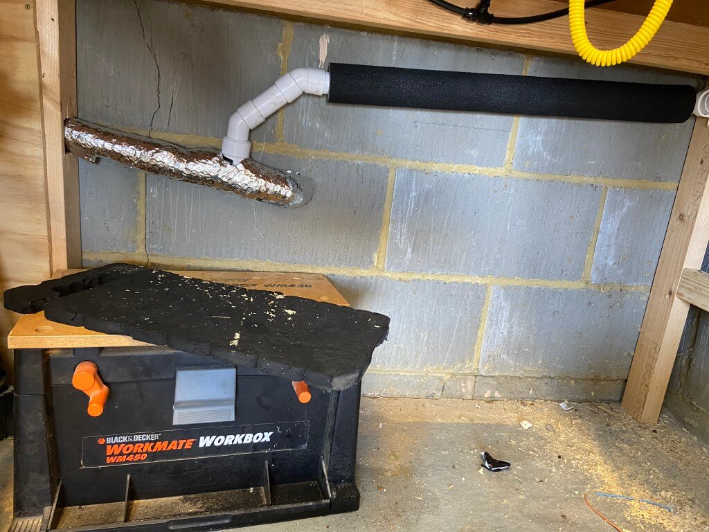
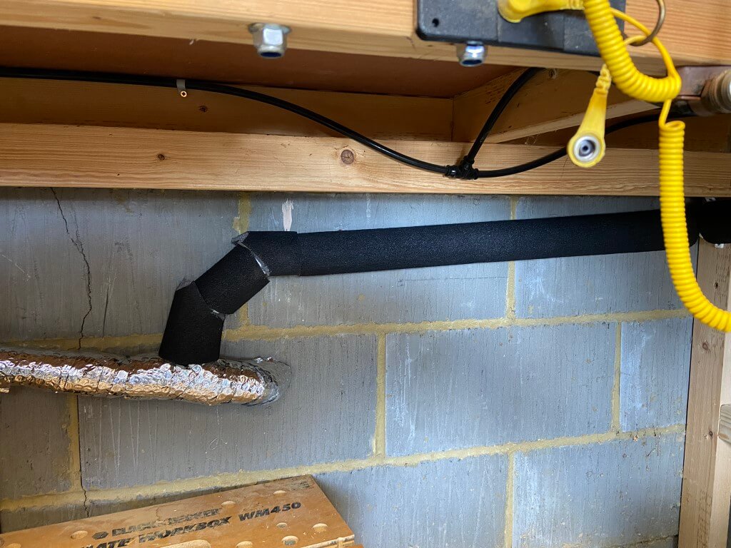
32mm pipe was then installed up to the boiler and insulated with Condensate Pro lagging .
The completed condensate runoff is higher than the utility sing waste to which I have connected, therefore, if the soil pipe backs-up, it will show a problem first in the utility.
Once all the pipe was lagged it was time for a coffee and give my knees a rest!
New boiler all installed and fully compliant.
Since this picture was taken the ideal magnetic filter now has an insulated jacket to cut down on losses.
I recenly refilled my central heating system after completely draining down to install an automatic bypass valve and then a partial drain down to install a Magnaclean filter a bit later on, when the system was refilled I used Fernox F1 inhibitor (£18.99 per 500ml), as I didn’t know the volume of water in the system to meet the required minimum of 5% inhibitor per 100 litres of system water, and to be on the safe side, I used two bottles of Fernox, as you can not overdose the system, but this is wasteful and not to mention expensive.
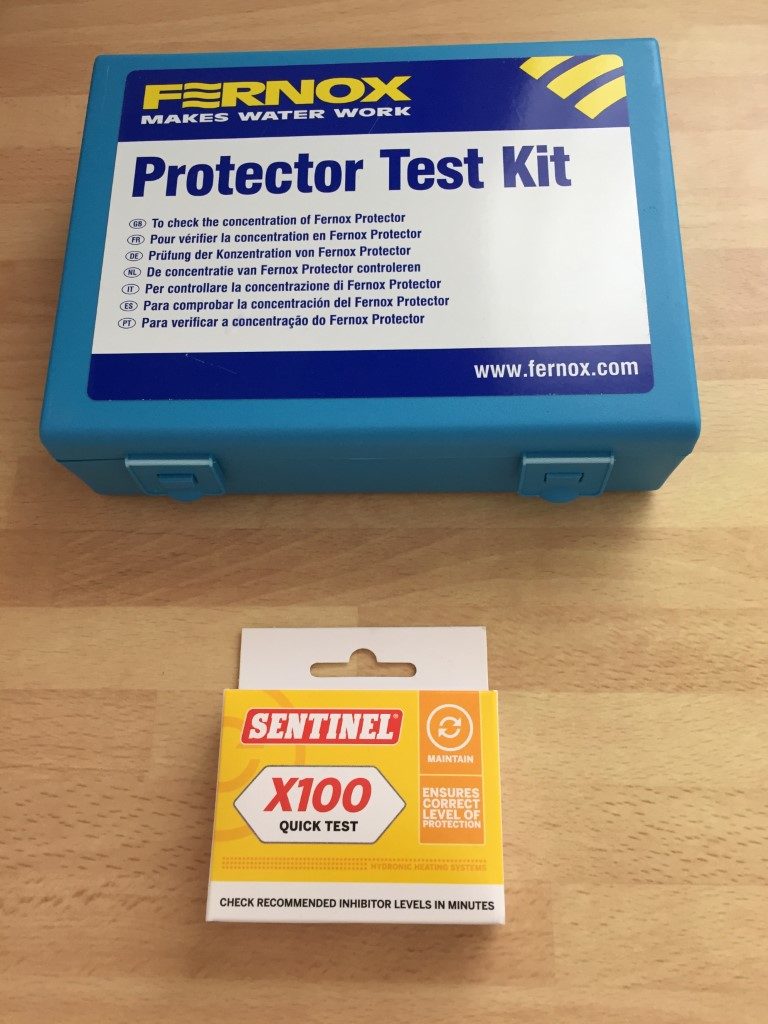
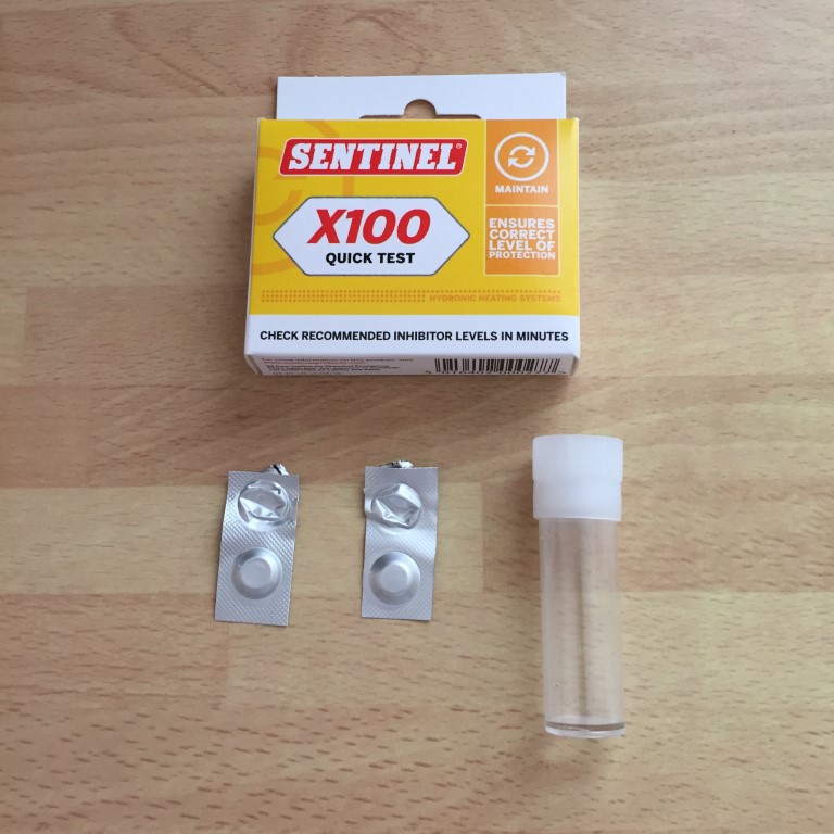
In order to use the correct amount of inhibitor, I needed to find the volume of water and ‘spend to save’, so I bought a couple of inhibitor test kits, a Fernox Protector Test Kit for £23.46 and Sentinel x100 quick test for £4.99.
So, why did I buy two test kits!
When the system was completely refilled I used Fernox F1, a few months later I decided to install the Magnaclean and needed some pipe fittings and inhibitor to top up the system resulting from the partial drain down, however, the merchant didn’t sell Fernox F1 only Sentinel x100, so I bought that.
Reading on a plumbing forum their was a suggestion that it was not a good idea to mix different manufactures inhibitor in the same system, I read this after I had already bought the x100 quick test kit off eBay.
I was refunded the cost of the x100 which was good of Plumb-It in Huntingdon, and bought Fernox F1 from another merchant and I also decided to buy as a long term investment a Fernox test kit.
As I now had two test kits, I thought I would see if the Sentinel x100 quick test would give an accurate indication of inhibitor strength of Fernox F1 as the x100 quick test kit will do two concentration tests for £4.99, rather than spend over £23, having said that, I can do 25 tests with the Fernox test kit, so it is cheaper overall, but as a DIY’r getting the x100 kit is more cost effective.
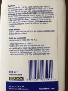
Reading the hazard data sheets for x100 and Fernox, they contained the same chemicals and concentrations, Fernox F1 had one further component:
(Fernox & Sentinel) <2.5% Benzotriazole
(Fernox & Sentinel) 5% Sodium Molydate
(Fernox) Nitrilotriethanol
So I decided to test if the X100 kit would work in practice.
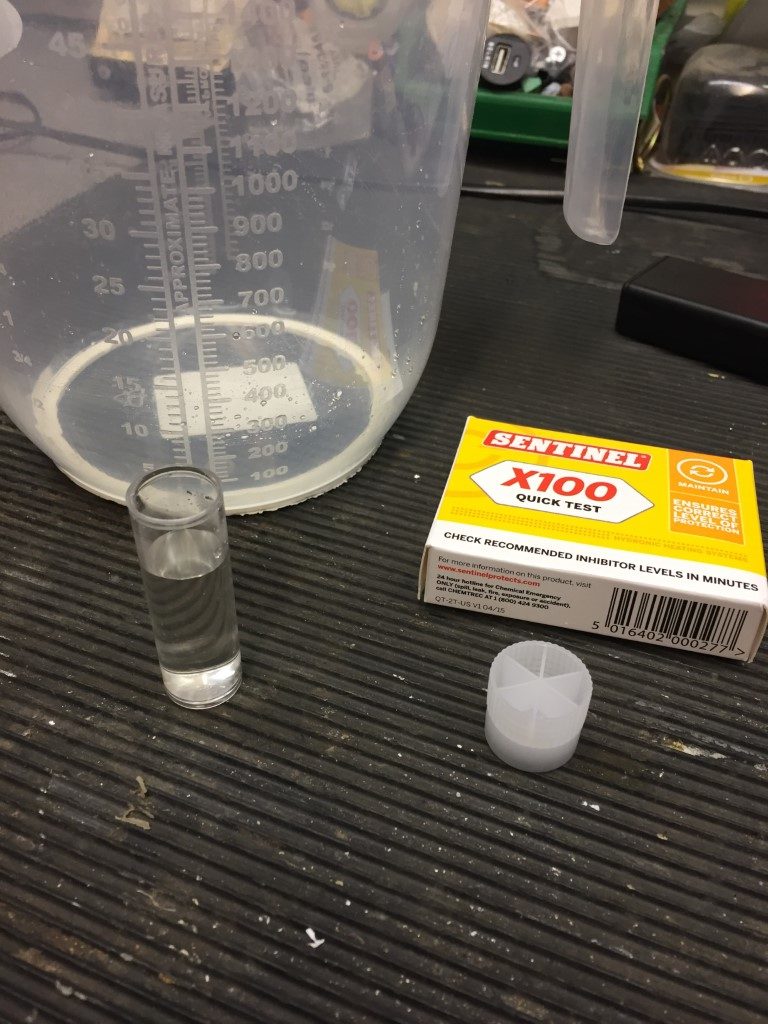
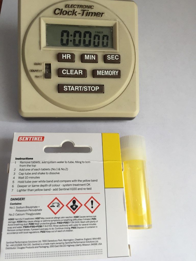
Running some system water off using the vent on the Magnaclean, you fill the container to 1cm from the top and add two tablets, shake and then wait 10 minutes, the colour of the solution should then be compared with back of the x100 packet, if its the same yellow colour or deeper, its fine.
Using the x100 test, the result appears my system water is of an adequate concentration.
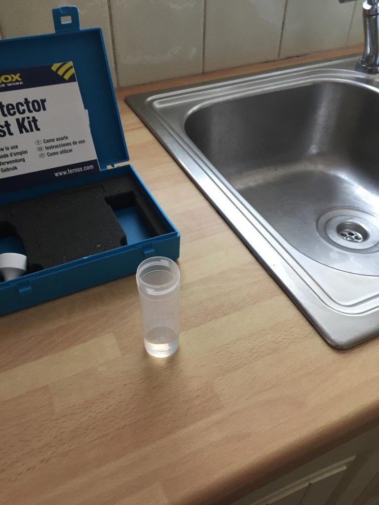
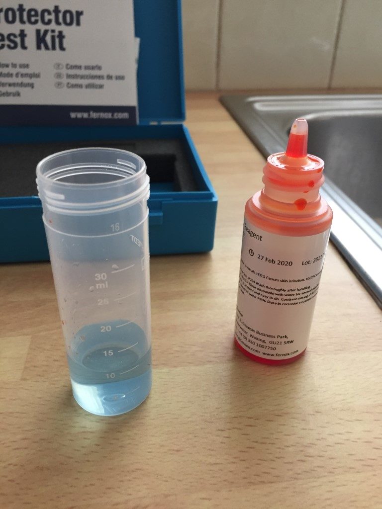
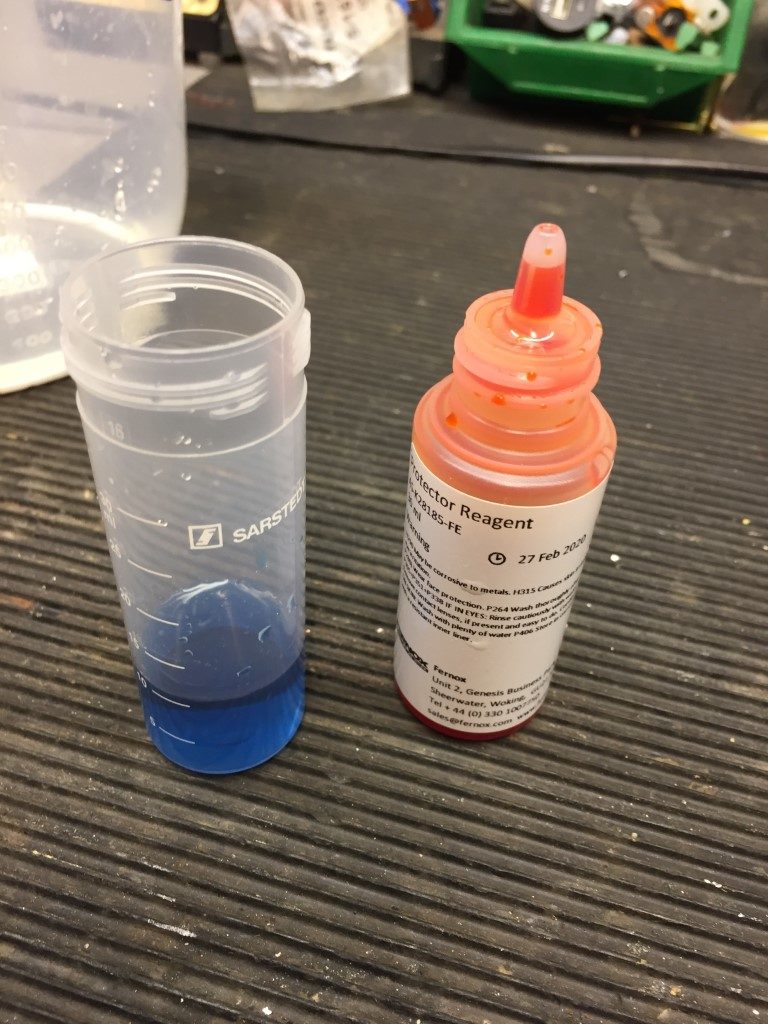
The Fernox Inhibitor Test Kit was slightly more involved than the x100 test, but not difficult, the first thing to do was establish as baseline for your cold water which was used to fill the heating system with water.
Filling the supplied container with 10ml of tap water, you add drops of the reagent and count the number of drops needed to change the solution from Blue to Orange.
This is after one drop.
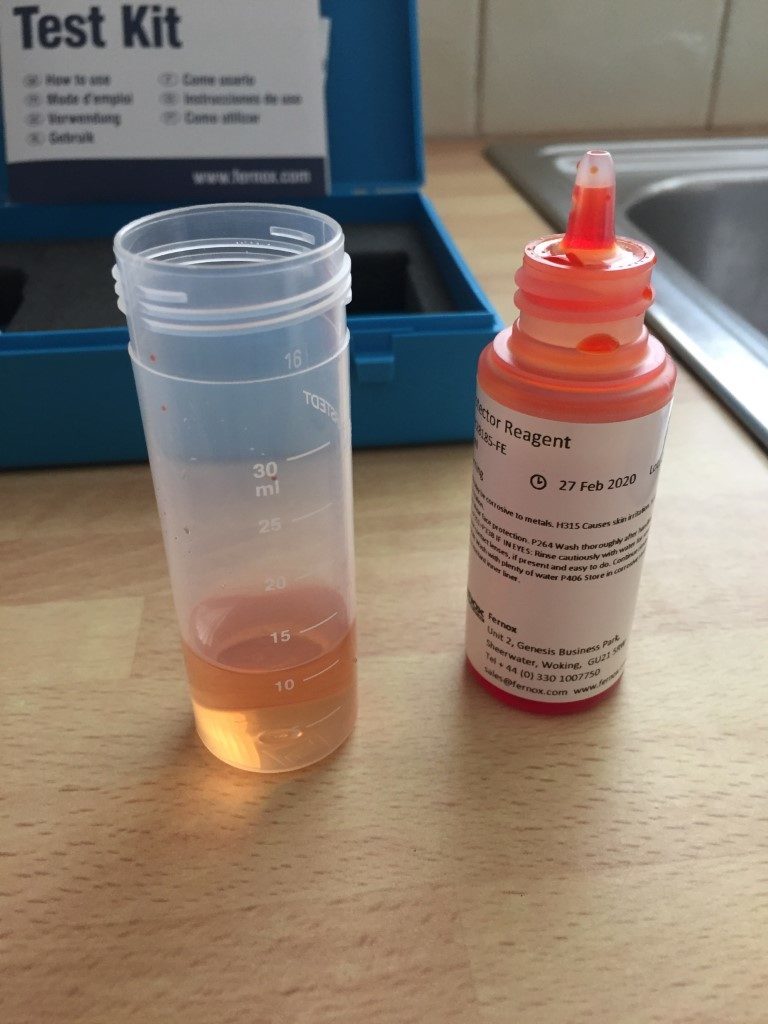
To change my tap water from Blue to Orange took four (4) drops of reagent, shaking the bottle after each drop, this number will be subtracted from the drops total in the next part.
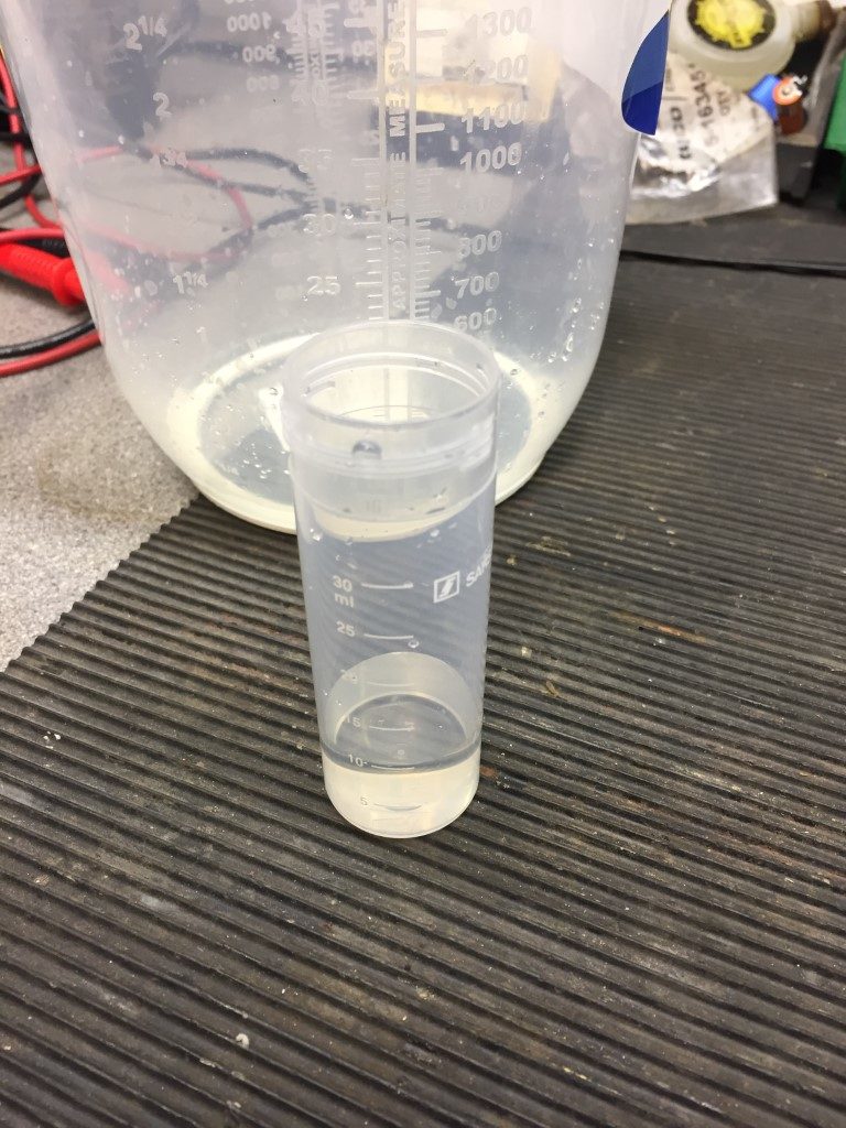
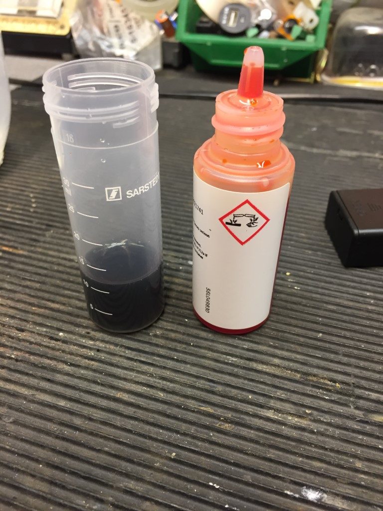
Washing out the container, I refilled this with central heating system water to 10ml as before.
One drop of reagent added.
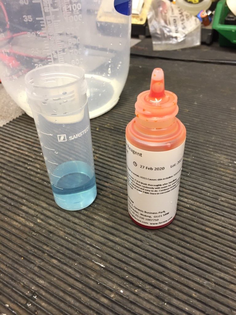
Nine drops of reagent added.
Very nearly there.
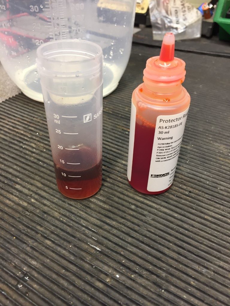
After 39 drops, the solution changed to Orange, subtracting the baseline tap water 4 drops, means that 35 drops were needed overall, referring to the kit instruction, for Protector F1 at the recommended dose of 500ml for 100L of system water, a minimum of 9 drops of reagent is required to change from Blue to Orange, obviously, I’m well overdosed!!
This got me thinking of how I can determine how much water is in the heating system, the Fernox web site suggests that in a domestic system, volume can be estimated by counting the number of single panel radiators in a property and multiplying by ten. remembering to count double panel radiators as two single panels.
I have 13 radiators with 3 of these being doubles, therefore, using the formula above, this would be 16 x 10 = 160 Litres of System Water needing just over 1.5 x 500ml bottles of Fernox F1.
To cross check this approximate value, I went the manufactures site for my radiators and found the data sheets, checking the sizes of my radiators against the Kw output of each one, this equaled a total of 10.87Kw, allowing that 1Kw requires 11 liters of water and adding a overhead of 25 litres for water in the boiler, indirect heating coil and system pipework, it worked out to 144.5 Litres of System Water needing just under 1.5 x 500ml bottles of Fernox F1.
The next time the system is completely drained I’ll use one 500ml bottle and then test to confirm if indeed it does need more than one bottle, once established I’ll sell the test kit on eBay.
Note – Boiler replaced, however Magnaclean has been retained, Blog HERE.
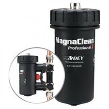
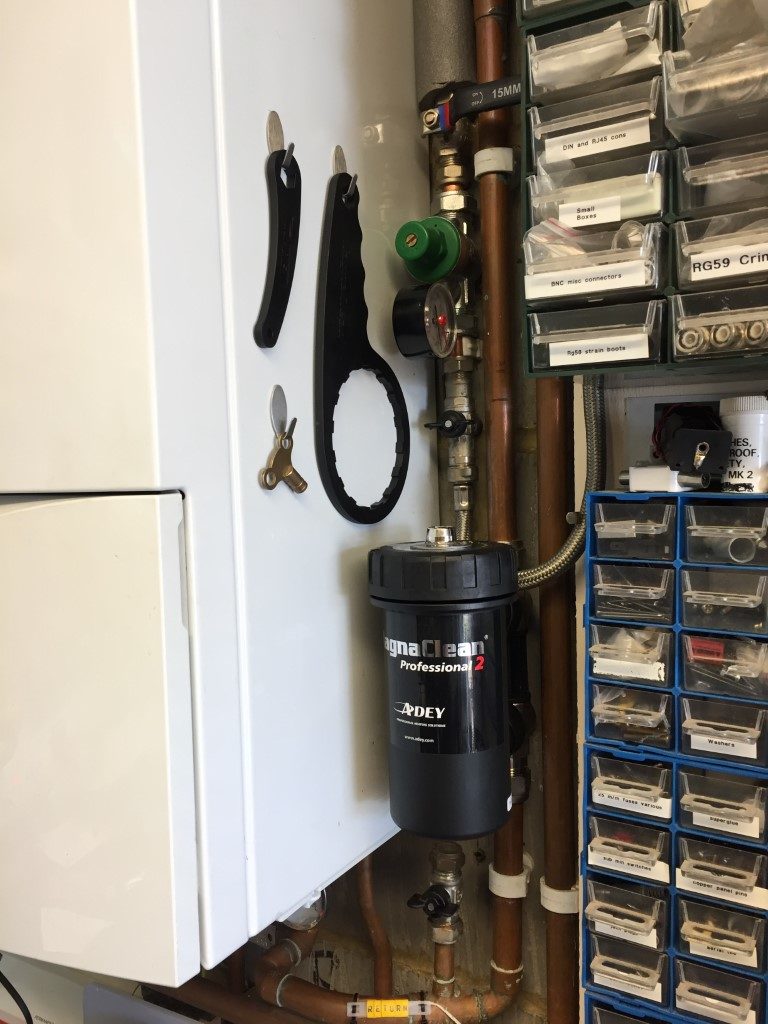
Today (21 April 18), I decided to install a Magnaclean Pro 2 in my heating system which has a system boiler with hot water and central heating controlled using the ‘S’ plan design.
Magnaclean removes suspended solids (ferrous (Magnatite) and non ferrous) from the circulating water and traps them within the canister, this is then cleaned out at regular intervals.
The removal of these particulates will improve the longevity of the boiler and its parts, although my system water has been previously treated with inhibitor and ran clear during the drain down to fit this, these devices are installed when boilers are replaced in compliance with Building Regulations Part L , so I thought I’d bring it up to code.
The instructions specify that the Magnaclean is installed on the return to the boiler after the last radiator and before any system filling/pressurisation point, next to the boiler was a good location for me.
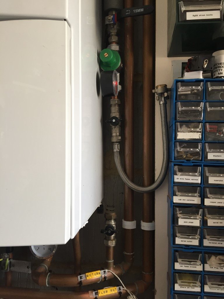
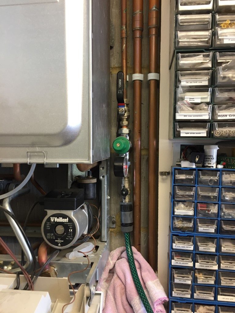
In order to make room for the Magnaclean to fit, the cold water filling loop needed to be raised.
With the boiler power isolated, the case was removed to give more working room, a hoselok fitting was screwed onto the cold fill line and a hose ran to drain, I then isolated at the stopcock and drain the line ready for cutting the 15mm copper pipe and raising the whole assembly.
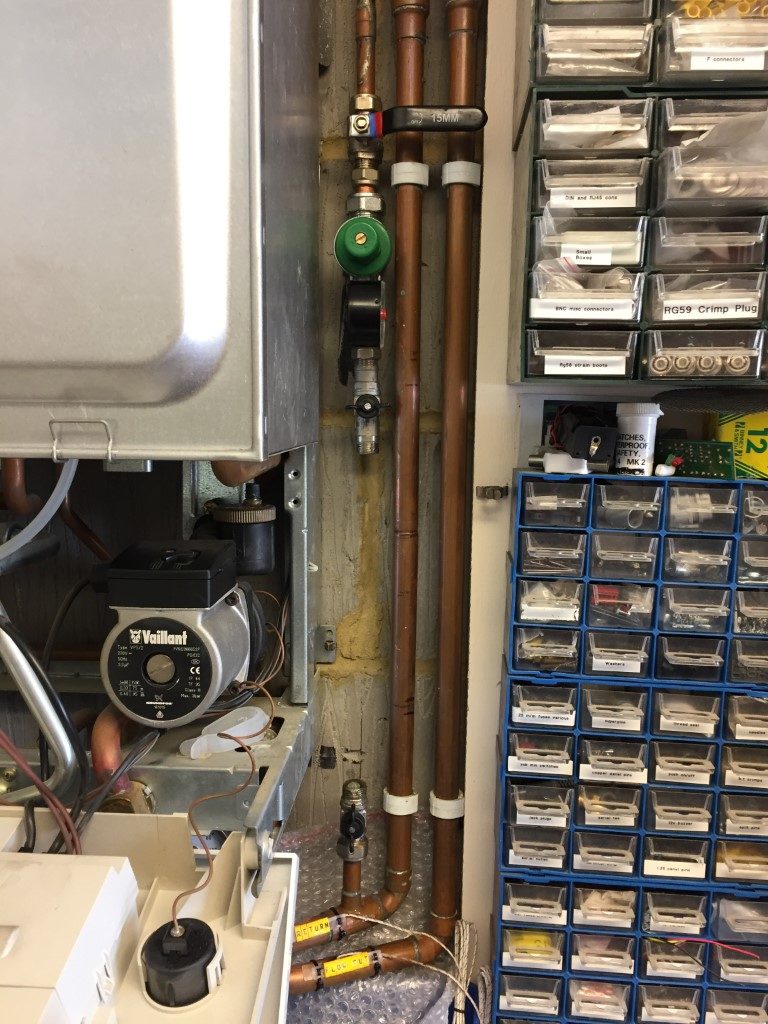
Cold fill raised and leak tested, the maximum height was governed by the length of the braided filling loop, the 22mm copper pipe nearest the boiler is the return and this has two marks 150mm apart indicating where the cuts need to be made.
I used the hoselok fitting on the return filling valve, and drained the heating system water opening a couple of upstairs radiators to break any vacuum.
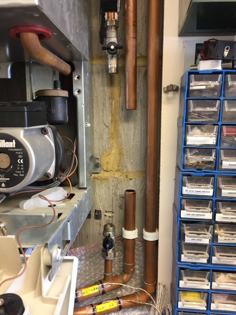
Using a 22mm pipe slice it was fairly easy to cut the pipe, due to the restricted working space, I had to use pump pliers to grip and turn the pipe slice through some of its travel.
The Magnaclean has a slip socket allowing the unit to slide over the pipe, then once engaged, the unit is lifted slightly so the inlet pipe engages allowing a nut and olive compression fitting to be made, I used jointing compound on both top and bottom olives before tightening.
The isolation valves are on the left, rather than the right, I had to use this orientation so I could easily access the isolation valves, I was going to use obtuse street elbows to form a tight set in the return pipe, lifting the Magnaclean clear of the flow pipe so I could operate the isolation valves, but this was way too much work for no real gain, especially as effective fluid flow is a function of the Magnaclean canister and not the valve orientation.
Once the canister was pushed into place and the lid was tight, I closed the radiator vents and started to fill the system watching for leaks, the filling system pressure reducing valve is set for 1.5bar, so this was left open as I went round venting the upstairs radiators.
With the first round of venting done, I vented the Magnaclean and boilers circulation pump before turning the boiler on to heat.
This was followed by more venting until the majority of the air subsided, I isolated the Magnaclean and drained it so I could add 500ml of Fernox F1 inhibitor to the system, using the canister as a dosing pot.
As I only partially drained the system, (downstairs radiators are below the boiler so I only drained upstairs), 500ml should be sufficient to top up protection.
The installation went well with no leaks, and once the Magnaclean was proved to be ok, I registered the device online for the 10 year warranty.
I’ll post pictures in a few weeks of the Magnaclean magnet to see what it has picked up.
5 May 18 – Checked the Magnaclean and this is what it had caught:
My Vaillant Thermocompact system was installed in 2003 and has 13 radiators piped in 10mm. I’m very happy with the low level of magnetite retained and nothing was trapped within the lower filter housing, I’ll check this again in a years time, but so far so good 🙂
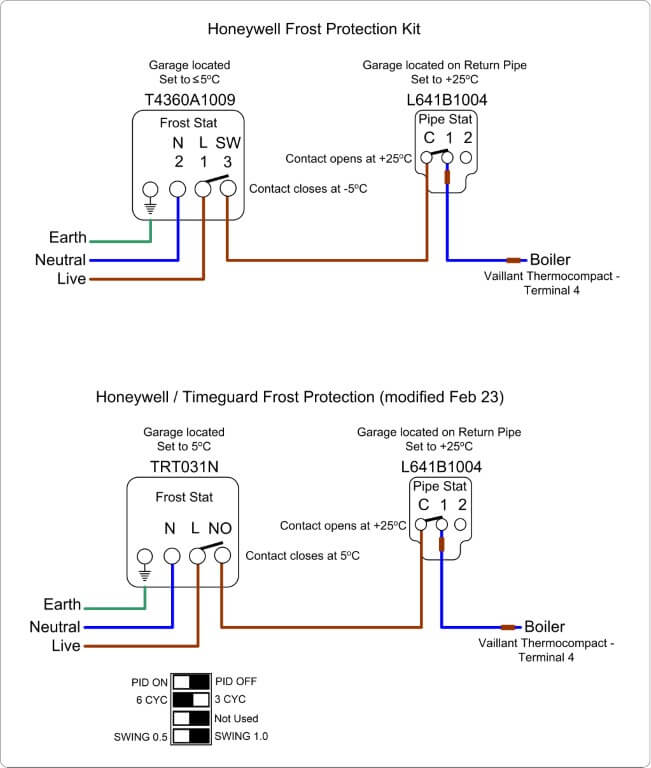
Due to the recent cold snap and the fact that my central heating boiler is in the garage, I thought I’d install frost protection which will override the heating controls and fire up the boiler when the frost stat air temperature is at or below +5℃, on the return pipework to the boiler is pipe stat set for +25℃ to turn the boiler off.
I have a Hive system which has a frost setting on the internal thermostat, this will bring the heating on if the temperature falls to +7℃ or below, the garage frost protection supplements this.
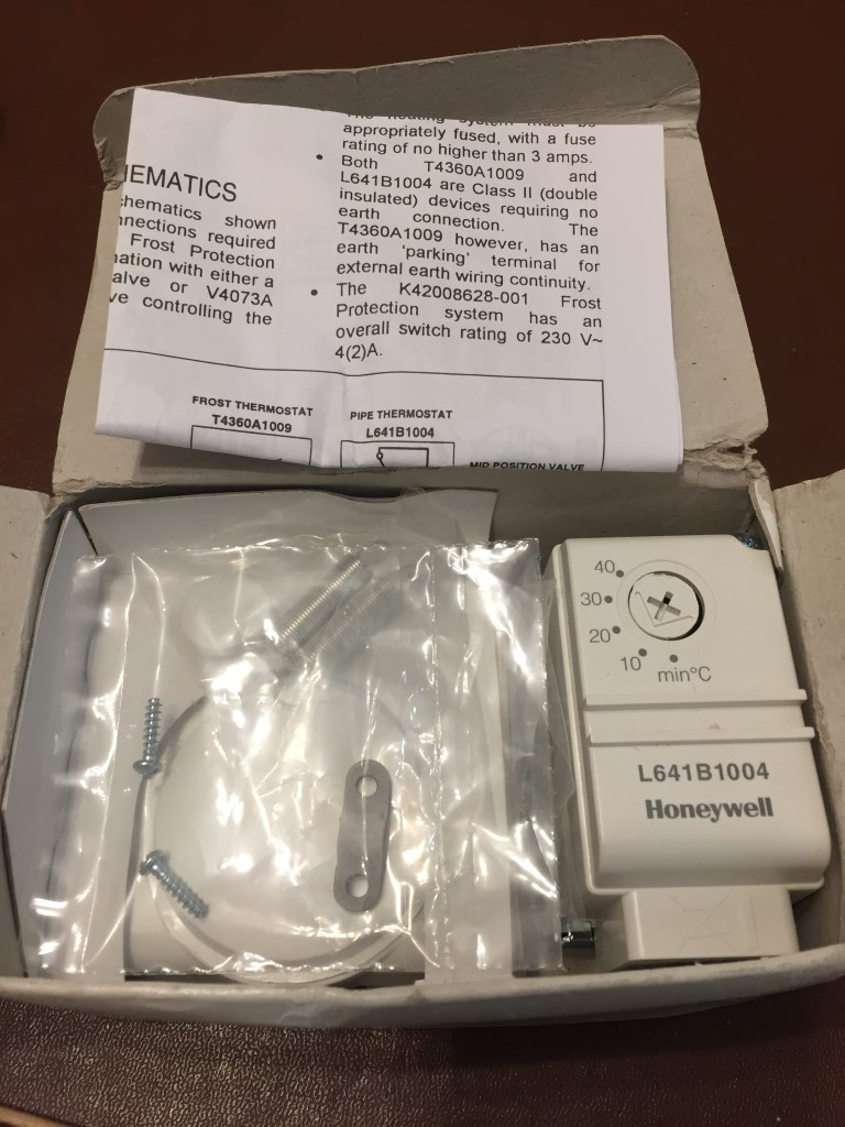
I spotted the Honeywell Frost Protection Kit – K42008628-001 comprising of a Frost Stat and Pipe Stat for £27.00 on eBay which is a really good price compared to Screwfix, Plumbase and Toolstation, so I bought it.
For the installation, apart from the stats, I needed some heat resisting cable for the pipe stat and a double mounting box.
2 core and earth (3093Y) 0.75mm2 heat resisting white round flexible cable was bought off the internet from Under Control Instruments (www.undercontrol.co.uk) for £4.00 which is temperature rated to 85℃.
The double gang surface box took a little bit of searching as I needed one with the flexibility to be used either vertically or horizontally with face-plates in the correct orientation, this cost £3.99 off eBay.
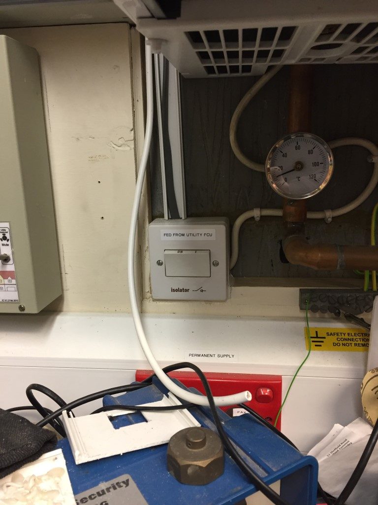
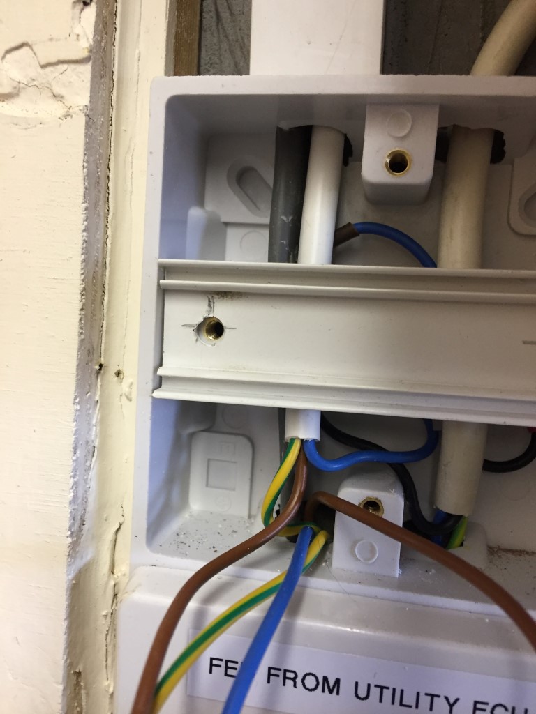
Original installation showing the boilers isolating switch, the white flex is from the pipe stat.
First job was to wire the pipe stat and install it on the return pipe to the boiler, the stat is held in place with a spring which hook onto lugs on the base of the stat, getting the spring behind the pipe and stretching it to fit was made easier by tying a piece of string to one end of the spring and passing that behind the pipe.
Hooking the spring on the stat lug and keeping tension on the string, offer the stat to the pipe and pull the string to stretch the spring round the back of the pipe and hook it on the opposite lug, once done the string is simply cut off, this worked very easily once you got the knack.
With the power isolated, the existing isolator was opened and a picture taken for reference.
The Blue (Neutral (N)), Yellow (system calling for heat – switched 230v (L2)) and Red (Live (L1)) are from the junction box wiring centre, the opposing wires in the isolator are to the boiler.
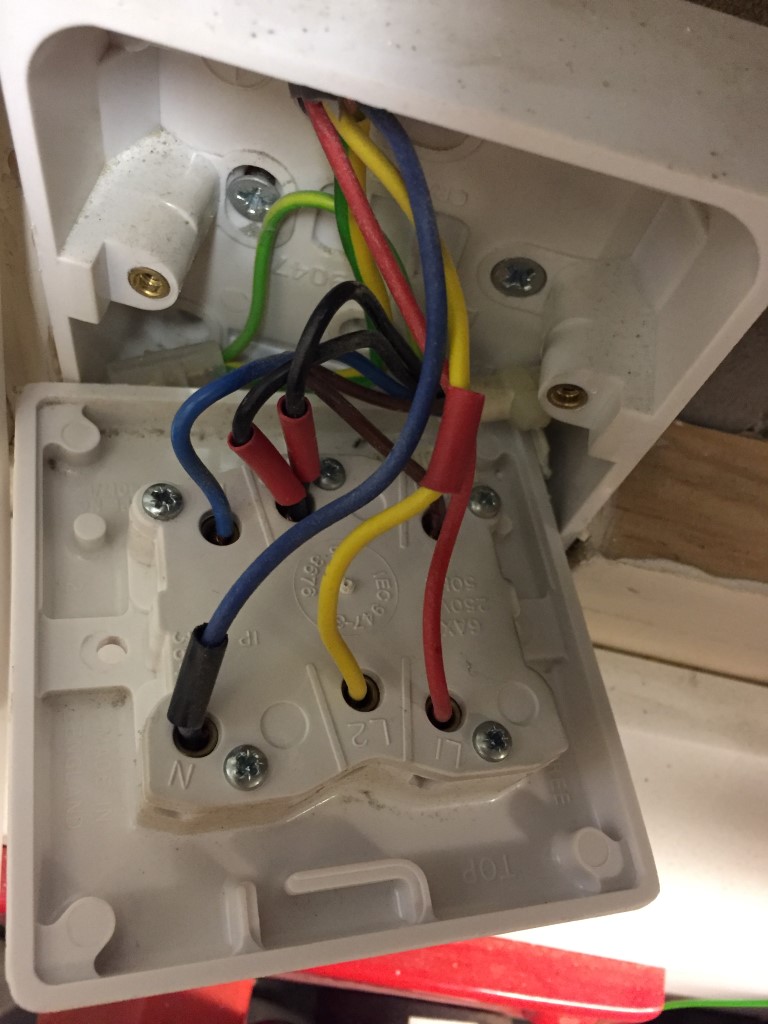
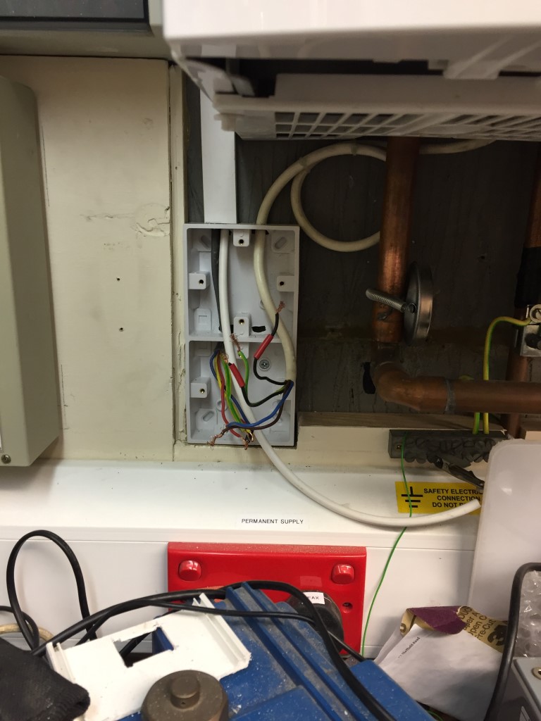
Once everything was identified and proved dead, the wiring was removed and the new double gang surface box was fitted and wires pulled back in.
The two red sleeved blacks were separated, one will be connected back into L2, the other will be used by the frost protection system.
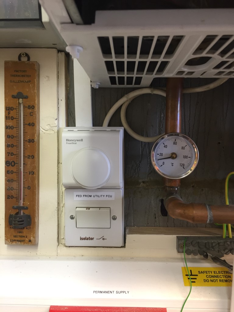
The isolator was wired up and screwed into place, then the frost stat was fitted but it did not sit right as it was very slightly smaller than the back box so I needed packing to make it level, for this I used an off-cut of trunking lid, which did the trick.
Once the Froststat was fixed in place and connected, the power was turned on and the frost protection tested by simulation that everything worked ok, including the operation of the Automatic Bypass Valve, once done the trigger temperature was set and the stat lid fixed in place.
I did notice a draft from behind my changeover switch on the left of the picture which was blowing across the face of the froststat, so I sealed the gap with decorators caulk to avoid inaccurate operation of the stat.
Froststat and isolator, I bought additional lower cover screws and two were missing, the part number is Vaillant 290811 Clips.
As I have recently installed an Automatic Bypass Valve, I have not connected the frost stat to any motorised zone valves, therefore, once the air temperature is at or below +5℃, a switched live will be applied to the boilers ‘calling for heat’ via the red sleeved black wire, the boiler will now fire and the circulation pump will operate.
As the motorised valves to either the central heating or hot water cylinder will be closed (‘S’ Plan system), the pumped water pressure will ‘lift’ the automatic bypass valve, maintaining a heated water flow to the boiler via the return pipework to which the pipe stat is affixed.
Once the return pipework is above +25℃, the pipe stat opens the series wired connection from the frost stat, this removes the switched live to the boiler, and the boiler enters ‘no heat run on mode’ before switching off.
The job took 2 hours and cost £35.00 and although we have never had a problem, the boiler and pipework in the garage should have had effective frost protection from day one.
Update
19 March 18 – The boiler came on unexpectedly and it was caused by the frost stat, closer inspection reveled that one of the bimetallic switch support pillar was snapped inside the unit, I’ve contacted the seller on eBay to see if I can get a replacement.
20 March 18 – eBay seller responded to my mail and is sending a replacement unit out.
24 March 18 – Replacement froststat arrived in good order and installed, all working now and the original unit sent back to the seller.
15 December 2022 – Had a few really cold days of around -5oC and the garage internal temperature sensor was reading 4.25oC
I took the cover off the frost stat and I must have moved the dial when I was replacing the lid as it was set below +5oC, I have readjusted this now, so all should be good.
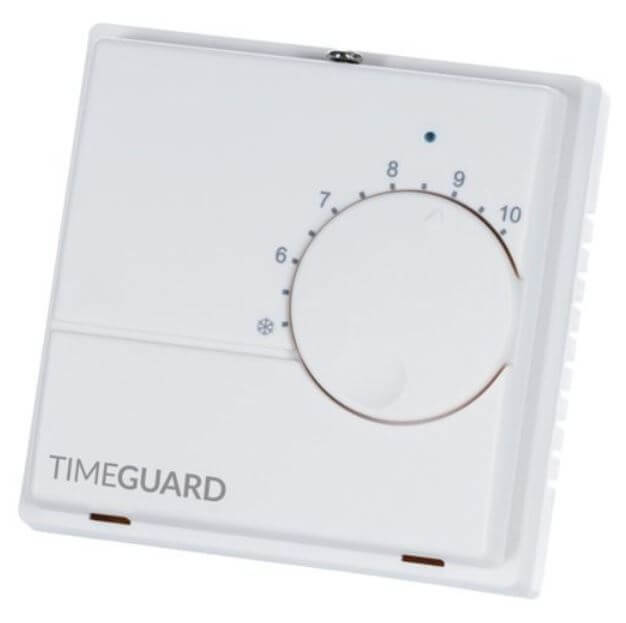
3 February 2023 – Timeguard TRT031N electronic frost thermostat arrived from Fastlec at a cost of £22.36.
I found the mechanical frost stat to be quite inaccurate, the replacement is electronic and should therefore be reliable.
6 January 2026 – Due to the addition of Opentherm Gateway control, external frost protection had to be disconnected as only Opentherm control can bring the boiler on, therefore, I’m now relying in the boilers internal frost protection.
A blog about stuff that interests me or I have done.
We use cookies on our website to give you the most relevant experience by remembering your preferences and repeat visits. By clicking “Accept All”, you consent to the use of ALL the cookies. However, you may visit "Cookie Settings" to provide a controlled consent.
This website uses cookies to improve your experience while you navigate through the website. Out of these, the cookies that are categorized as necessary are stored on your browser as they are essential for the working of basic functionalities of the website. We also use third-party cookies that help us analyze and understand how you use this website. These cookies will be stored in your browser only with your consent. You also have the option to opt-out of these cookies. But opting out of some of these cookies may affect your browsing experience.
Necessary cookies are absolutely essential for the website to function properly. These cookies ensure basic functionalities and security features of the website, anonymously.
Cookie
Duration
Description
_GRECAPTCHA
5 months 27 days
This cookie is set by the Google recaptcha service to identify bots to protect the website against malicious spam attacks.
cookielawinfo-checkbox-advertisement
1 year
Set by the GDPR Cookie Consent plugin, this cookie is used to record the user consent for the cookies in the "Advertisement" category .
cookielawinfo-checkbox-analytics
11 months
This cookie is set by GDPR Cookie Consent plugin. The cookie is used to store the user consent for the cookies in the category "Analytics".
cookielawinfo-checkbox-functional
11 months
The cookie is set by GDPR cookie consent to record the user consent for the cookies in the category "Functional".
cookielawinfo-checkbox-necessary
11 months
This cookie is set by GDPR Cookie Consent plugin. The cookies is used to store the user consent for the cookies in the category "Necessary".
cookielawinfo-checkbox-others
11 months
This cookie is set by GDPR Cookie Consent plugin. The cookie is used to store the user consent for the cookies in the category "Other.
cookielawinfo-checkbox-performance
11 months
This cookie is set by GDPR Cookie Consent plugin. The cookie is used to store the user consent for the cookies in the category "Performance".
CookieLawInfoConsent
1 year
Records the default button state of the corresponding category & the status of CCPA. It works only in coordination with the primary cookie.
PHPSESSID
session
This cookie is native to PHP applications. The cookie is used to store and identify a users' unique session ID for the purpose of managing user session on the website. The cookie is a session cookies and is deleted when all the browser windows are closed.
viewed_cookie_policy
11 months
The cookie is set by the GDPR Cookie Consent plugin and is used to store whether or not user has consented to the use of cookies. It does not store any personal data.
Functional cookies help to perform certain functionalities like sharing the content of the website on social media platforms, collect feedbacks, and other third-party features.
Performance cookies are used to understand and analyze the key performance indexes of the website which helps in delivering a better user experience for the visitors.
Analytical cookies are used to understand how visitors interact with the website. These cookies help provide information on metrics the number of visitors, bounce rate, traffic source, etc.
Cookie
Duration
Description
_ga
2 years
The _ga cookie, installed by Google Analytics, calculates visitor, session and campaign data and also keeps track of site usage for the site's analytics report. The cookie stores information anonymously and assigns a randomly generated number to recognize unique visitors.
_ga_92TJCVGJP2
2 years
This cookie is installed by Google Analytics.
_gat_gtag_UA_48800884_1
1 minute
Set by Google to distinguish users.
_gid
1 day
Installed by Google Analytics, _gid cookie stores information on how visitors use a website, while also creating an analytics report of the website's performance. Some of the data that are collected include the number of visitors, their source, and the pages they visit anonymously.
CONSENT
2 years
YouTube sets this cookie via embedded youtube-videos and registers anonymous statistical data.
is_unique
5 years
StatCounter sets this cookie to determine whether a user is a first-time or a returning visitor and to estimate the accumulated unique visits per site.
is_visitor_unique
2 years
StatCounter sets this cookie to determine whether a user is a first-time or a returning visitor.
sc_is_visitor_unique
2 years
StatCounter sets this cookie to determine whether a user is a first-time or a returning visitor.
Advertisement cookies are used to provide visitors with relevant ads and marketing campaigns. These cookies track visitors across websites and collect information to provide customized ads.
Cookie
Duration
Description
NID
6 months
NID cookie, set by Google, is used for advertising purposes; to limit the number of times the user sees an ad, to mute unwanted ads, and to measure the effectiveness of ads.
VISITOR_INFO1_LIVE
past
A cookie set by YouTube to measure bandwidth that determines whether the user gets the new or old player interface.
YSC
session
YSC cookie is set by Youtube and is used to track the views of embedded videos on Youtube pages.
yt-remote-connected-devices
never
YouTube sets this cookie to store the video preferences of the user using embedded YouTube video.
yt-remote-device-id
never
YouTube sets this cookie to store the video preferences of the user using embedded YouTube video.
yt.innertube::nextId
never
This cookie, set by YouTube, registers a unique ID to store data on what videos from YouTube the user has seen.
yt.innertube::requests
never
This cookie, set by YouTube, registers a unique ID to store data on what videos from YouTube the user has seen.