

My central heating system has 13 radiators with 12 having Thermostatic Radiator Valves (TRV), and I decided a couple of years ago to replace the existing wax capsule TRVs with intelligent Hive ones which I did.
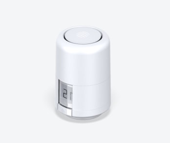
Installation of the Hive TRV was very straightforward, the existing heads are removed by unscrewing the knurled nut and the Hive supplied adapter is screwed into place on the valve body, the Hive TRV then screws to this and using the App is enrolled onto the heating system.
Hive TRVs have picked up negative reviews, I think this was due to launching the product before it had been fully beta tested, that said, most of the wrinkles have now been ironed out and I enjoy the benefits individual radiator temperature control and scheduling gives me.
My main issue has been that the Hive TRVs, which are controlled via a smartphone app, and this keeps requesting that the TRV’s need calibration, which I have put down to the age and condition of the existing radiator valves.
I could temporarily free sticking valve pins by ‘tapping’ and adding oil or WD40, but they would always stick again, and they did look a bit mangy, also my boiler pressure was dropping very slowly over time and I put this down to TRV valve leaks, so it was time for action!
Honeywell VT15 TRVs
The TRVs installed when the house was built (circa 2002) are VT15:
Unfortunately the valve has no serviceable parts and therefore no replacement insert is available which is a nonsense to be honest, as it forces you to either buy a complete valve assembly with TRV sensing head or search for a vendor who will sell the valve body only.
After much searching, I found a seller on eBay of VT15 valve bodies only at £6.99 each, so I bought what I needed which is a lot cheaper than buying a complete assembly for £15 each and throwing half of it away.
I had no intention of changing the valve body on the radiator as it would only introduce more work and an elevated risk of leaks from pipework joints, only the insert needed to be changed, so when I received the valves the inserts had to come out.
I had to use a 19mm socket in an Impact Screwdriver to remove the inserts from the new valves as they are insanely tight, so make sure the valve is held tightly in a solid vice before trying this.
Fitting Inserts
After switching power off to the boiler, I drained the water out of the heating system, this was easy in my case as the downstairs radiators had drain valve lockshields.
After removing the Hive TRV head, you can see the hexagonal head of the valve insert, using the Impact Screwdriver, the old insert was swiftly removed and the new insert fitted and carefully tightened with a 19mm ring spanner.
As the insert uses ‘metal- to metal’, mating face with the valve body to form a seal, I used V2-Plus jet lube jointing compound on the threads and joint face as a precaution against leaking.
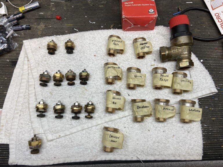
I changed 11 inserts, on investigation 1 was OK, 10 were sticking or stuck in the closed position and of the 11, 7 showed signs of leaking.
While the system was drained I changed the Automatic Bypass Valve (ABV) for a better quality Honeywell DU145, although my boiler has an inbuilt ABV for boiler protection, it is prudent to have one installed with TRVs as the external ABV is designed to maintain a minimum pump flow rate through the boiler as the individual radiator TRVs close and to manage boiler over-run when zone valves close, rather than ‘dead heading’ the pump forcing the boiler ABV to open.
When all the inserts and the ABV was fitted, Fernox F1 inhibitor was added via Magnaclean filter chamber and the system filled with water, circulated and vented.

Why lubricating the TRV pins doesn’t work
Not being a plumber, I decided to cut open a TRV valve body to see how it work and where it fails.
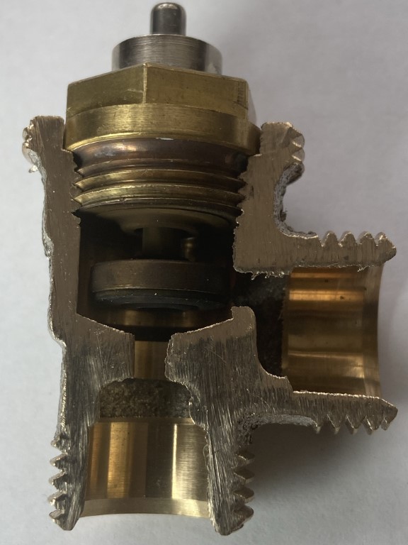
Insert Operation.
Water from the heating system enters at the bottom of the valve body, as the valve plunger is away from the valve seat (room asking for heat), water will pass and exit to the radiator.
If the pin on the top of the insert, (which is under spring pressure to keep the plunger lifted), is slowly pressed down, this will begin to restrict the water flow to the radiator as the plunger lowers into the valve seat, eventually closing the central heating water off completely to the radiator.
The job of the TRV head is to push down on this pin based on the rooms ambient temperature.
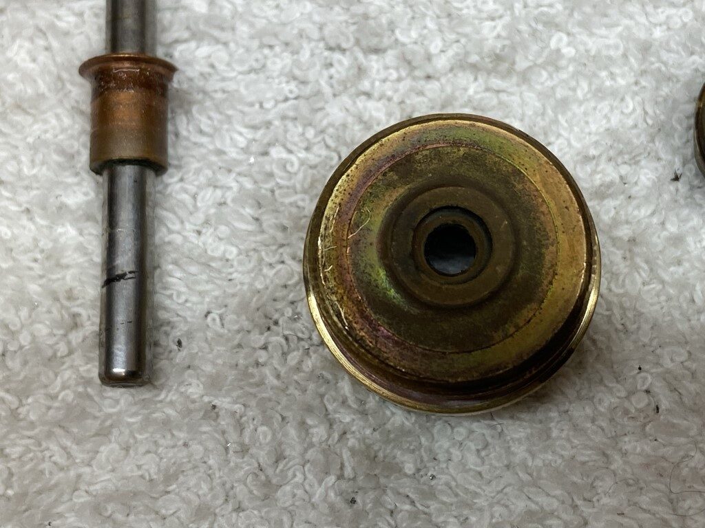
The movement of the pin is not very much at all :
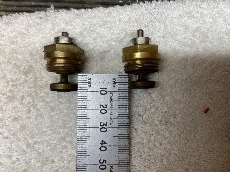
The plunger on the left is stuck in the lowered position, the one on the right is OK as the internal spring has overcome friction and lifted the plunger.
So what’s inside an insert?
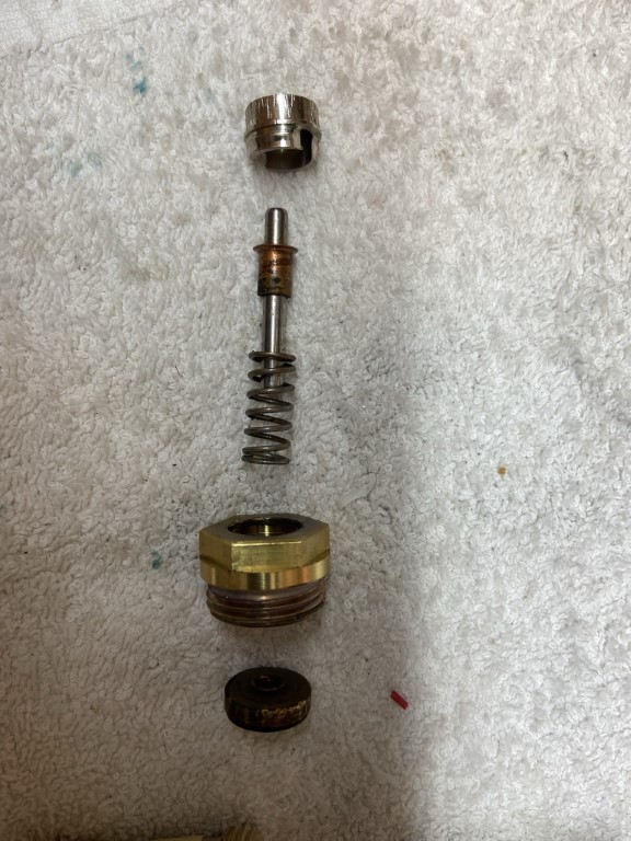
Starting at the bottom of the insert, this is in contact with the central heating water, the first part is the plunger which has a disk of rubber, copper riveted to it, this forms the watertight seal when the plunger is pushed fully down into the seat of the valve body.
The plunger is pushed tightly onto a stainless steel pin allowing the pin to raise and lower the plunger, the pin passes through a rubber seal in the body of the brass insert.
With the pin in the body, a spring sits over the pin and a copper ferrule holds the spring in place.
The last part is the stainless steel collet which is held in place by a ribbed design, locking into the brass body when pushed in.
The action of locking the collet in to the body, compresses the spring, forcing the copper ferrule to seat against the underside of the collet and lifting the pin to the correct height to enable the plunger to be lifted clear of the valve body seat.
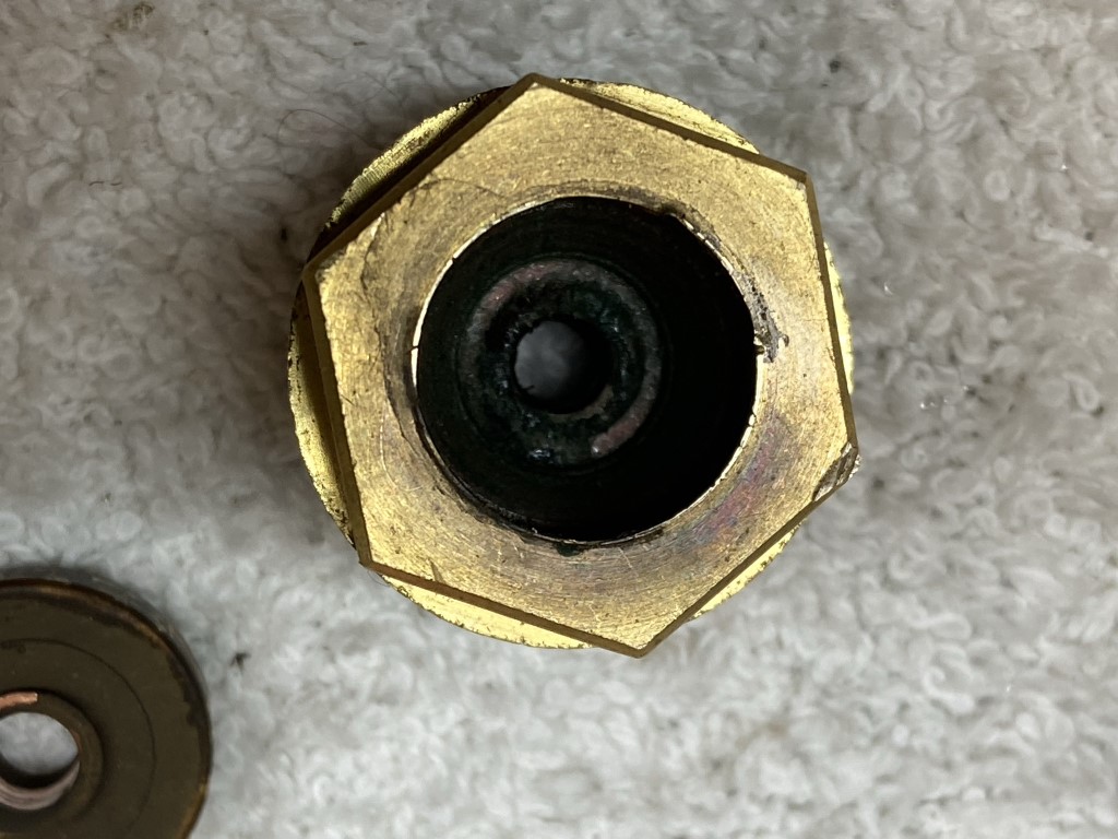
Where are the problem areas?
The majority of my problems were due to the pin sticking, the root cause is where the pin passes through the rubber seal at the base of the brass insert body, and no amount of lubrication will get anywhere near it.
It looks like the rubber seals have age hardened due to being subject to wide temperature variations over time, eventually the seals friction against the pin overcomes the springs lifting force.
As a result of the pin seal ageing, system water creeps into the insert cavity, making its way past the locking joint of the collet/body or collet/pin, manifesting as discolored caking at the interface, this is an area for ‘weeping’ as the gunge is damp and therefore a point where system pressure is lost.
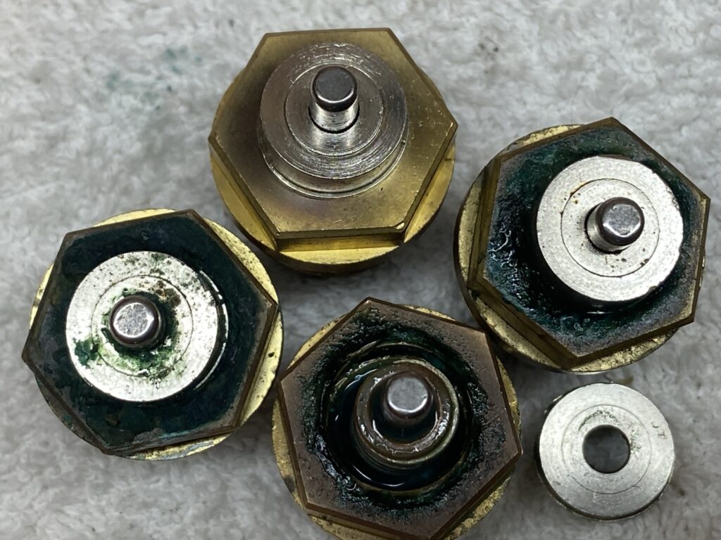
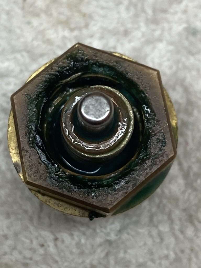
This picture says it all, the top insert shows how a good one should look, with the pin freely moving when pressed down using an upturned spoon.
To Sum Up
Don’t waste your time lubricating or tapping TRV pins like I did, the pin is sticking at the seal and no amount of lubricant will fix it 🙁 .
If the pin sticks or gunge is evident, you are only putting off the inevitable valve change, a plumber can do what I did a lot quicker and in some cases without draining the system, however, it is a DIY job if your confident.
Hope you found this useful.