Tag Archives: plumbing

Magnaclean Pro 2 Installation

Updated 19 April 2023

Note – Boiler replaced, however Magnaclean has been retained, Blog HERE.

MAGNA

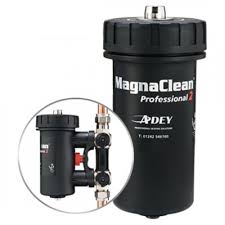
Today (21 April 18), I decided to install a Magnaclean Pro 2 in my heating system which has a system boiler with hot water and central heating controlled using the ‘S’ plan design.

Magnaclean removes suspended solids (ferrous (Magnatite) and non ferrous) from the circulating water and traps them within the canister, this is then cleaned out at regular intervals.

The removal of these particulates will improve the longevity of the boiler and its parts, although my system water has been previously treated with inhibitor and ran clear during the drain down to fit this, these devices are installed when boilers are replaced in compliance with Building Regulations Part L , so I thought I’d bring it up to code.

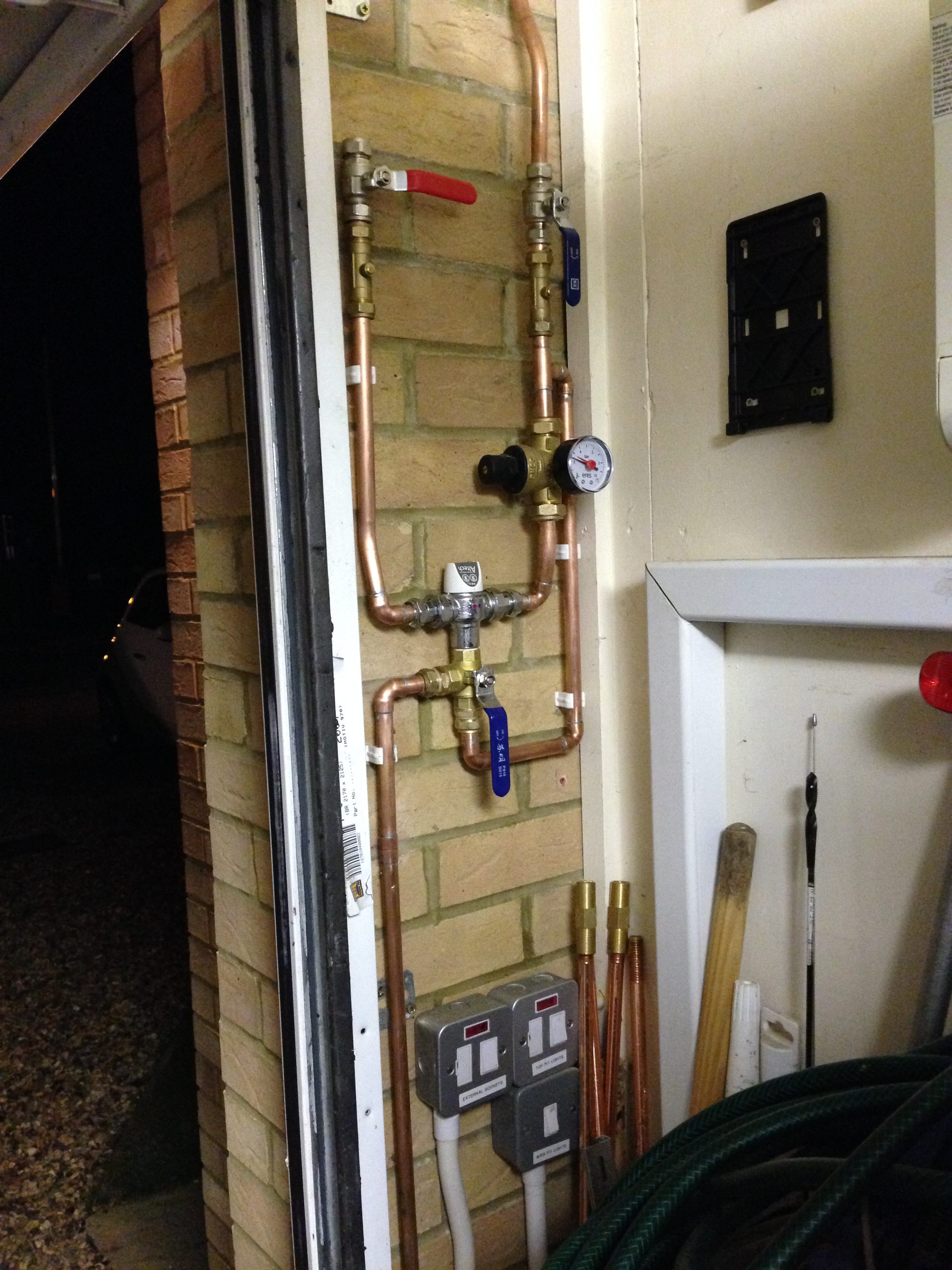
The instructions specify that the Magnaclean is installed on the return to the boiler after the last radiator and before any system filling/pressurisation point, next to the boiler was a good location for me.

before

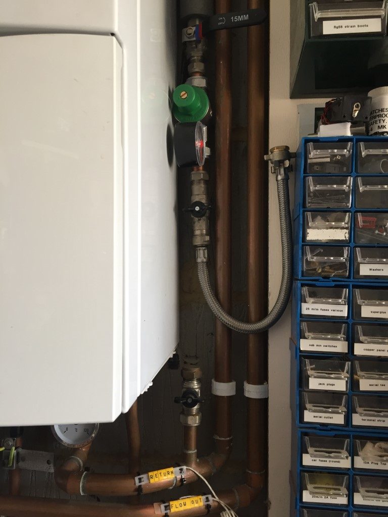
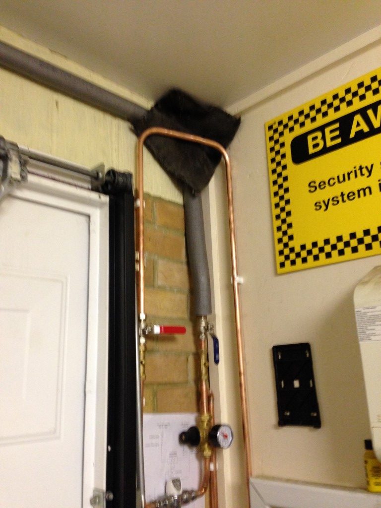
In order to make room for the Magnaclean to fit, the cold water filling loop needed to be raised.

drain

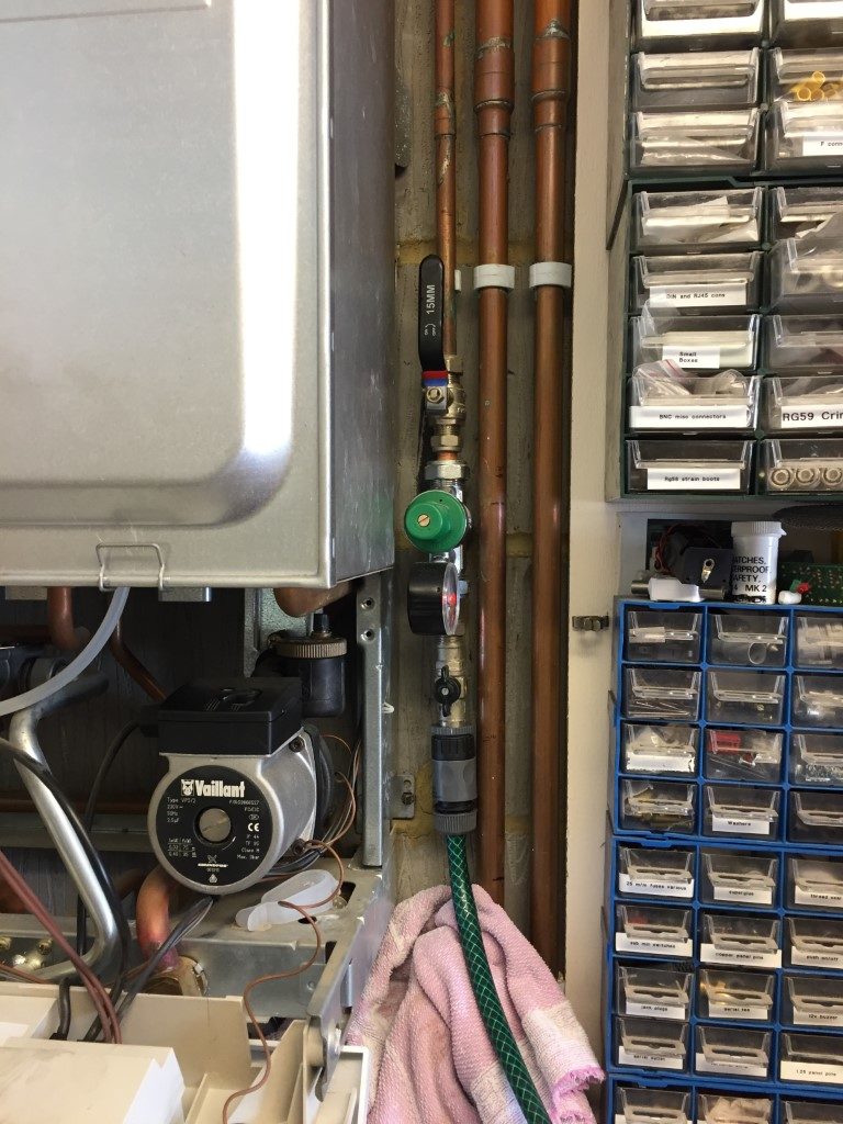
With the boiler power isolated, the case was removed to give more working room, a hoselok fitting was screwed onto the cold fill line and a hose ran to drain, I then isolated at the stopcock and drain the line ready for cutting the 15mm copper pipe and raising the whole assembly.

lifted

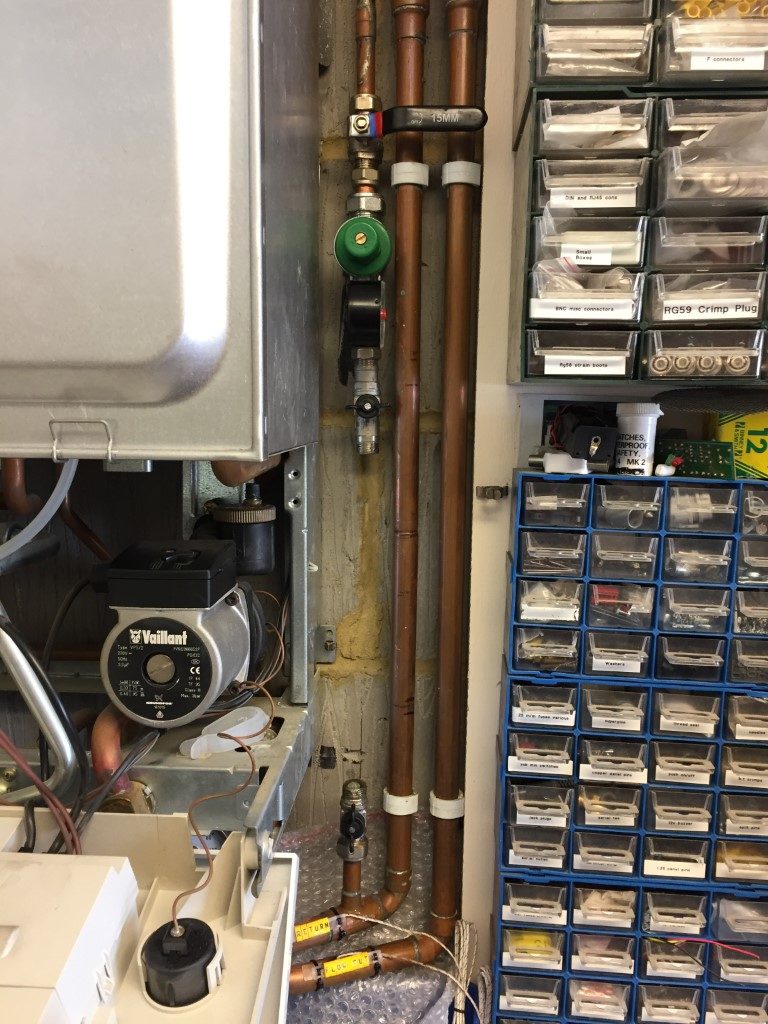
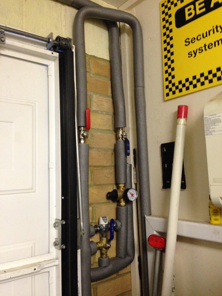
Cold fill raised and leak tested, the maximum height was governed by the length of the braided filling loop, the 22mm copper pipe nearest the boiler is the return and this has two marks 150mm apart indicating where the cuts need to be made.

I used the hoselok fitting on the return filling valve, and drained the heating system water opening a couple of upstairs radiators to break any vacuum.

pipe slice

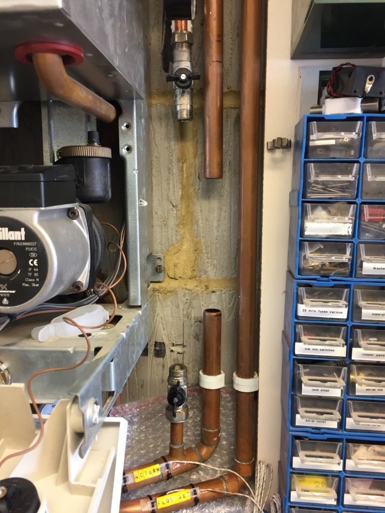
Using a 22mm pipe slice it was fairly easy to cut the pipe, due to the restricted working space, I had to use pump pliers to grip and turn the pipe slice through some of its travel.

magnaclean base

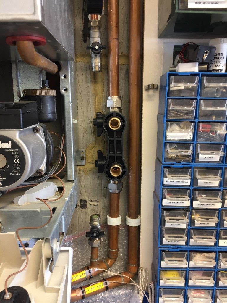
The Magnaclean has a slip socket allowing the unit to slide over the pipe, then once engaged, the unit is lifted slightly so the inlet pipe engages allowing a nut and olive compression fitting to be made, I used jointing compound on both top and bottom olives before tightening.

The isolation valves are on the left, rather than the right, I had to use this orientation so I could easily access the isolation valves, I was going to use obtuse street elbows to form  a tight set in the return pipe, lifting the  Magnaclean clear of the flow pipe so I could operate the isolation valves, but this was way too much work for no real gain, especially as effective fluid flow is a function of the Magnaclean canister and not the valve orientation.

finished

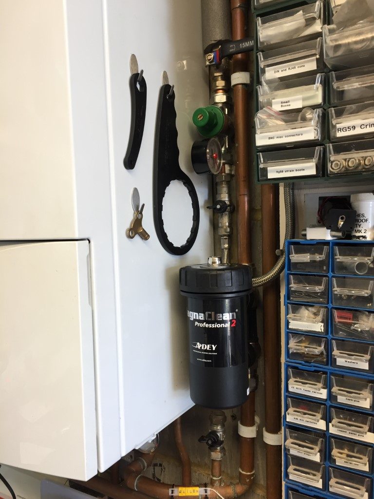
Once the canister was pushed into place and the lid was tight, I closed the radiator vents and started to fill the system watching for leaks, the filling system pressure reducing valve is set for 1.5bar, so this was left open as I went round venting the upstairs radiators.

With the first round of venting done, I vented the Magnaclean and boilers circulation pump before turning the boiler on to heat.

This was followed by more venting until the majority of the air subsided, I isolated the Magnaclean and drained it so I could add 500ml of Fernox F1 inhibitor to the system, using the canister as a dosing pot.

As I only partially drained the system, (downstairs radiators are below the boiler so I only drained upstairs), 500ml should be sufficient to top up protection.

The installation went well with no leaks, and once the Magnaclean was proved to be ok, I registered the device online for the 10 year warranty.

I’ll post pictures in a few weeks of the Magnaclean magnet to see what it has picked up.

5 May 18 – Checked the Magnaclean and this is what it had caught:

magnatite

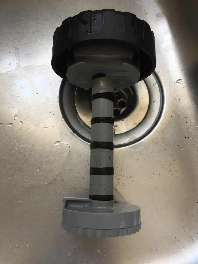
My Vaillant Thermocompact system was installed in 2003 and has 13 radiators piped in 10mm.  I’m very happy with the low level of magnetite retained and nothing was trapped within the lower filter housing, I’ll check this again in a years time, but so far so good 🙂

ESi Electronic Hot Water Cylinder Thermostat – ESCTDE/B – Part 1

UPDATED -27 April 2022

Background

In order to save energy and better regulate the temperature of my domestic hot water in my Santon Premier Plus unvented cylinder, I decided to install a ESCTDE/B Electronic Dual Cylinder Thermostat manufactured by ESI Controls, I bought online from PlumbNation.

box

Installation

The ESCTDE/B has two thermisters, one for the temperature reading and control, the other is for over-temperature trip and is set for 80℃, I must have a big problem if this operates as my boiler output temperature is set to 68℃.

thermistor

Fortunately the Santon Premier Plus has a spare dry thermostat pocket which the thermistors are a perfect fit.

pocket

I marked the location of the thermister pocket on the outside of the cylinder cover and offered up the ESCTDE/B back-plate and marked the centre hole.  I’m not sure what the ESCTDE/B is specifically designed to fit, but the rear fixing was perplexing and I didn’t want to modify the casing of the unit in case I invalidated the warranty.

back
Rear fixing arrangment

I used a cut down 20mm Female Adapter as a center bush, this was cut to size and fixed to the front cylinder cover.

bush
20mm Female Adapter
bush
Cut down female adapter used as a through cover fixing method.
bush
Fixing bush installed.
bush
Inside cover showing bush and thermostat pocket.

ESCTDE/B fixed to the bush with the three back-plate screws and as the female adapter has a serrated edge, it holds very well, the existing cylinder thermostat was turned up to position 5 which is 72℃, I have left this in circuit as another backup to over-temperature, as mentioned earlier, my boiler output temperature is set to 68℃, so only under a fault condition should this protection operate.

fixed
Indirect temperature setting and top view of fixing to ESCTDE/B.
Cover
Thermistors sliding into cylinder pocket.

Connections

NOTE – The mains supply to the ESCTBE/B MUST be from the same source as the heating systems programmer, this will ensure that there is only one point of electrical isolation for safe working.

I used 1mm 4 core and earth from the ESCTDE/B to the heating connection box, the ESCTDE/B does not have an earth connection, so this wire was parked, the unit requires a permanent 230v feed, the temperature calling relay changeover contacts are NOT volt free, although they are simply wired in series with the existing cylinder thermostat.

If the Legionella setting is active on the ESCTDE/B, the unit will automatically switch 230v to the Domestic Hot Water motorised valve (NOTE- this overrides any programmer settings), which in turn will bring on the heating, the output from the ESCTDE/B will remain on for 1 hour when the tank temperature is above 61℃.

As the bending radius of the connecting wires within the unit is quite tight, I used ferrules on the end of the wires, this ensures that no ‘whiskers’ can cause problems later.

wire
Ready for wire stripping.
wires
Insulation removed and conductors twisted.
wire
Bootlace ferrule pushed on.
wires
Bootlace crimped and job done.

Conclusion

Finished installation all working, as my hot water system is directly fed, (no header tank), I did not need to enable the ‘disinfection mode’, this mode increases the water temperature to 61℃ for 1 hour to kill Legionella, however, as the feature exists, I set it to activate once per week.

finished
We had been away for a few days hence the water temperature was showing 21℃, the unit was initially set for 48℃ and the Red LED shows the cylinder is calling for heat.
finished
Picture showing wiring from ESCTDE/B to heating terminal box and the tank temperature now reached the set-point of 48℃.

Problem

Apologies for not updating this blog and a recent comment made me revisit this, so thank you.

I have decide to make a Part 2 to the ESi showing how I addressed the problem of the the heating coming on outside of the scheduled time due to the ‘legionella’ setting being on.

Part 2 is HERE.

Central Heating Enhancement

I was reading on the plumbing forums about the need for an Automatic Bypass Valve (ABV) on central heating systems and compliance with the HM Government  document – Domestic Building Services Compliance Guide, specifically the need for a ABV (page 15, section 2.0).

I have a System configuration using a Valliant Thermocompact 624e boiler, the purpose of the ABV is to maintain a consistent flow through the boiler and also should both the hot water and central heating zone valves close due reaching the set point temperature, the boiler will continue to run for 10 minutes to dissipate heat in the the boilers heat exchanger, without some form of bypass the pump will be pumping against closed valves, which is not good!

The ABV senses the increase in pump pressure and opens against a calibrated spring pressure to maintain water flow.

S Plan

My central heating system had a 15mm hand valve cracked open between the boilers flow and return for this purpose, the 28mm pipe with an automatic air vent is the feed from the boiler, the centre 22mm pipe is the return.

start

The advantage of this configuration is that the pump can not pump against a dead head, the disadvantage is that a portion of the heated water from the boiler is immediately returned to the boiler and not used the heat radiators or hot water, so I thought I’d install an Automatic Bypass Valve not realising that the boiler already had an inbuilt one until I had bought all the parts…oh well!!

The manual bypass valve was not the only thing I wasn’t entirely happy with, the main niggles were the motorised valve to the heating circuit was mounted very low and it would be better to move it higher for ease of replacement and the automatic air vent was not at the recommended height above the highest point in the system, both of these were going to be fixed at the same time as the installation of the ABV.

First job was to electrically isolate all power to the boiler and controller, once done it was a matter of draining the system down, I’m fortunate that my radiators have drain valves, this made the process very simple.

Once drained I could disassemble the pipework.

strip

I retained the hand valve for adding inhibitor and for use as a vacuum break should I need to drain down in the future.

Once the pipework was apart, I used a 22m straight compression coupling to extend the central heating pipe, lifting the motorised valve  to a more accessible location, the pipe to the automatic air vent was also extended to be 300mm above the height of the upstairs radiators.

The tricky job was to unsolder a 22mm stub which was cut to allow the pipework to come apart.

solder

With the heat mats in place, I was surprised how easy it was to desolder the stub from the feed pipe elbow, once the stub was out, I could start to  dry fit the pipework so that the ABV exit pipe was directly inline with the return from the hot water cylinders heating coil.

Once everything was aligned, I removed the head of the ABV so as not to melt anything inside it when I started soldering the fittings.

finished

This is the finished job, I used another compression fitting on the return pipework to make any future ABV replacement easier as the whole assembly can be broken down, something you cant do with soldered fittings.

British Gas replace one of the motorised valve heads and they don’t open the Honeywell junction box to connect the new head wiring, they add an external junction box which looked naff, so I remade the head cable off as it should be done.

The system now needed to be refilled, I coupled a length of 15mm copper pipe with a tundish to the original hand valve and added 1 litre of Fernox Protector F1, once done the pipe was removed, valve closed and a screw cap was fitted.

Mine is a closed system with no head tank, a filling loop from the cold water feed is used to add water and pressurise the system, as I knew there would be a lot of radiator venting, I installed a water pressure reducing valve inline with the double check and isolating valve already installed, this allowed me to set the filling pressure at 1.2bar and leave the valve open, rather than continually repressurising the system after venting air, this worked really well and saved loads of time.

loop

The picture was taken after all the air in the system was vented and the boiler pressure was 1.4bar and steady with no leaks, the loop was disconnected and capped off until next required.

To keep a beady eye on the the pressure over the nest few days I used a home CCTV system 🙂

pressure

The main problems I had was not having all the correct fittings to hand when you have to adapt from the original plan, I started the job on a Saturday morning just in case, and fortunately Screwfix is not too far away and they had everything in stock, including a new 22mm pipe slice as mine had packed it.

One thing which bothers me is that the builder used copper pipe where it can be seen and plastic where it can’t, this means that as your cutting pipe, it starts to turn inside the transitional coupling!!

I hate with a passion plastic fittings and have little confidence in them, fingers crossed they will last the test of time.

Hot Water to Outside Tap

When we first moved into the house I installed an external bibcock tap which I fed by ‘teeing’ into the cold water feed line in the garage which is  used for the combination boilers filling loop.

In the previous house I had hot and cold available outside to wash the car, so the project was to do the same here. The two problems were the lack of available hot water pipes in the garage and no more wall space to add another external bibcock dedicated to hot water.

First things first, locate a source for the hot water, fortunately on the other side of the garage wall is a small utility room with a sink and plumbing for a dishwasher and washing machine.

Isolating the cold water fill to at the tank, I drained the hot water down into the utility sink and emptied the dead leg of the washer fill line using the tap at the bottom of the pipe, once this was done, I put the plug in the sink and removed the sinks waste pipe for ease of access to where I would be cutting and soldering.

Drilling a 15mm hole through into the garage from the house was easy as the internal double skin walls are built using low density thermalite block.

Pipe installPutting some tape over the open end of pipe, I pushed it through the hole into the garage where I soldered an end fed elbow with stub to a compression fitting isolation valve. From the isolation valve a stub with a tee and drain cock were soldered.  A stub pipe from the tee had a plastic stop end fitted, the pipe was then pushed back into securing clips fixed to the garage wall.

soldered bridgeUsing the pipe slicer tool shown in the first picture, I cut out a small section out of the hot pipe and put on a 15mm copper tee, using a half crossover to bridge the cold pipe, I then used a short piece of pipe to connect an elbow to the pipe to the garage.

Once the dry fit went ok, I dissembled it all to clean and flux the pipe and fittings before soldering, all the fitting were end fed here.

Once all the joints were soldered and making sure all the valves are closed, I cracked open the hot water tank fill valve and went to check for leaks after venting air from the system and running water through the garage drain valve to flush out any debris.

Pipe pull

The garage has been converted into a workshop and I didn’t want to damage any exposed pipe  when I throw stuff for storage, so the best option was to use plastic pipe and fish it behind the false wall as their was just enough room.

Drilling 110mm holes, allowed me plenty of room to push trunking lids taped together for the 4.5m run, string was attached to the end of the lid and pushed in place.

At the other end it was a pain to fish for the string using a torch, mirror and bent hook, however, once grabbed, I tied on stronger blue rope  to the string and pulled this back to secure on the pipe as shown, (the last thing I wanted to repeat fishing!).

At the utility isolation valve end, I clipped the John Guest Layflat Speedfit pipe to the wall and used a cold form bend to hold its radius and take strain off the ‘plastic to copper’ coupling.

The design to allow me to use one external bibcock tap was to use a three port valve, this suggestion came from DIYNOT plumbing forum.

SchematicParts

The pressure reducing valve, 3 port valve, double checkvalves and themostatically controlled valve were from eBay, all other parts from Screwfix.

How it works

The cold water has a local isolation valve for ease of maintenance, a double check valve stops contaminants getting back into the upstream water system, a ‘tee’ allows the pressure reducing valve to be bypassed, and if the 3 port valve is in the right position, allows full mains pressure at the outside tap for use with the hose.

The pressure reducing valve is set for 3.5bar which is the same water pressure as my unvented hot water tank, therefore the water pressure for both feeds to the thermostatically controlled valve (TCV) is the same.

The hot water also has a local isolation valve and double check valve before it feeds the TCV, the temperature of the blended water leaving the TCV is 42C.

Garage pipeAs the cold water was available, I connected this first to the valve and allowed pressure testing, the biggest problem I had was sealing the 1/2″ BSP threads on the 3 port valve.

I tried using fibre washers, PTFE tape and jointing paste but a couple of joints would still weep very slowly over time.  I searched the problem in the DIYNOT forum and the advice from experienced plumbers was to use Locktite 55 , following the instructional video on the locktite site, I applied the sealing material onto the prepared threads and it worked, no more leaks.

At the end near the bibcock tap, I used another ‘plastic to copper’ coupling and piped up and over to the hot water isolation valve.

A hot water drain cock was installed where the pipe emerged from behind the false wall so I can drain down if needed.

Hot pipeThis shows the hot water pipe coupling about to be soldered, hence the heat resisting mat, on the right of the picture is the cold water valve which is open and testing for leaks.

In the garage is another isolation valve directly behind the bibcock, this stops unauthorised use of the external tap.

The final job was to flush the system thoroughly and check that the water coming out of the bibcock tap is at the correct temperature, once proven, all exposed pipes were insulated and where the risk of damage was high, boxed in.

The most expensive part of the job was the plastic pipe as this comes in a minimum of a 25m roll and I only needed 4.5m. The option of pulling in straight lengths with a connecting coupling behind the false wall was discounted as I didn’t want any inaccessible joints, so I had no choice but to pay for more than I needed.

Apart from hassle of sealing the weeping threads, the job went well and I’m happy with the result.

Lagged pipe