After playing with a Programmable Logic Controller (PLC) to operate my radio mast, I decided to build a simulator in order to better understand the capabilities of the EASY PR-18DC-DA-R.
I wanted the simulator to have 16 inputs, either momentary or switched and the ability to import signals including an embedded 4 – 20mA current.
I had a sloped project enclosure already, so I made a dimensioned drilling template.
Once the template was stuck down, the pilot holes were drilled, template removed and holes opened to the right sizes.
The template was created in Visio and I used layers, one of the layers was for switch position drilling and alignment cross-hairs, turning that layer off (missed one in I8!), allowed me to print on self-adhesive sticky Matte White Vinyl.
Using a sharp knife, I cut though the Vinyl and started fitting the switches, buttons, Output indication LEDs and 4 – 20mA injector.
Terminal posts next.
Front panel populated.
Wiring started.
After a couple of changes, the internal wiring is completed and loomed in.
The simulator uses 24v DC, I used a small 1.5A output switched mode PSU for this, fed via a chassis fuse holder with the supply from an IEC male socket, the output from the PSU is fused separately.
PLC simulator all powered up, the program in the PLC was legacy from my mast control project, this will be overwritten by downloading revised programs from xLogicsoft software.
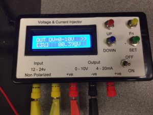
To complement the PLC simulator I bought a4-20mA Current Signal Generator 0-10V Voltage Generator Transducer Simulator for £19.00.
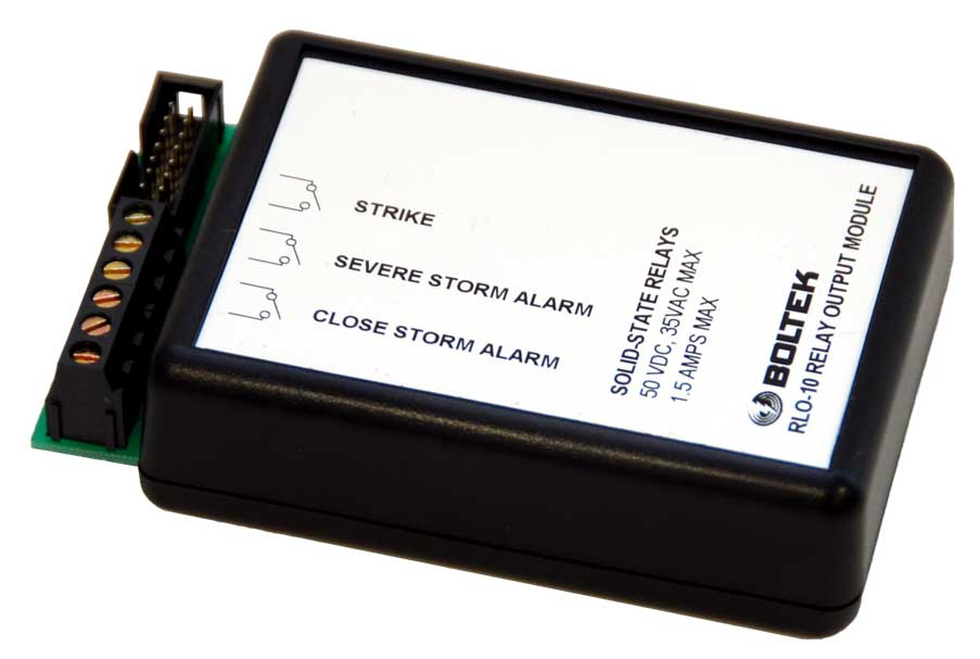
The LD-250 Lighting Detector from Boltek has an internal output for a relay interface, the manufactures units are quite expensive, so I decided to make my own.
RLO-10 Boltek Relay Interface
Inside the LD-250 is a 14 way header which connects via ribbon cable to the RLO-10, off eBay I bought the 14 way ribbon cable and IDC cable mount socket for £5.00.
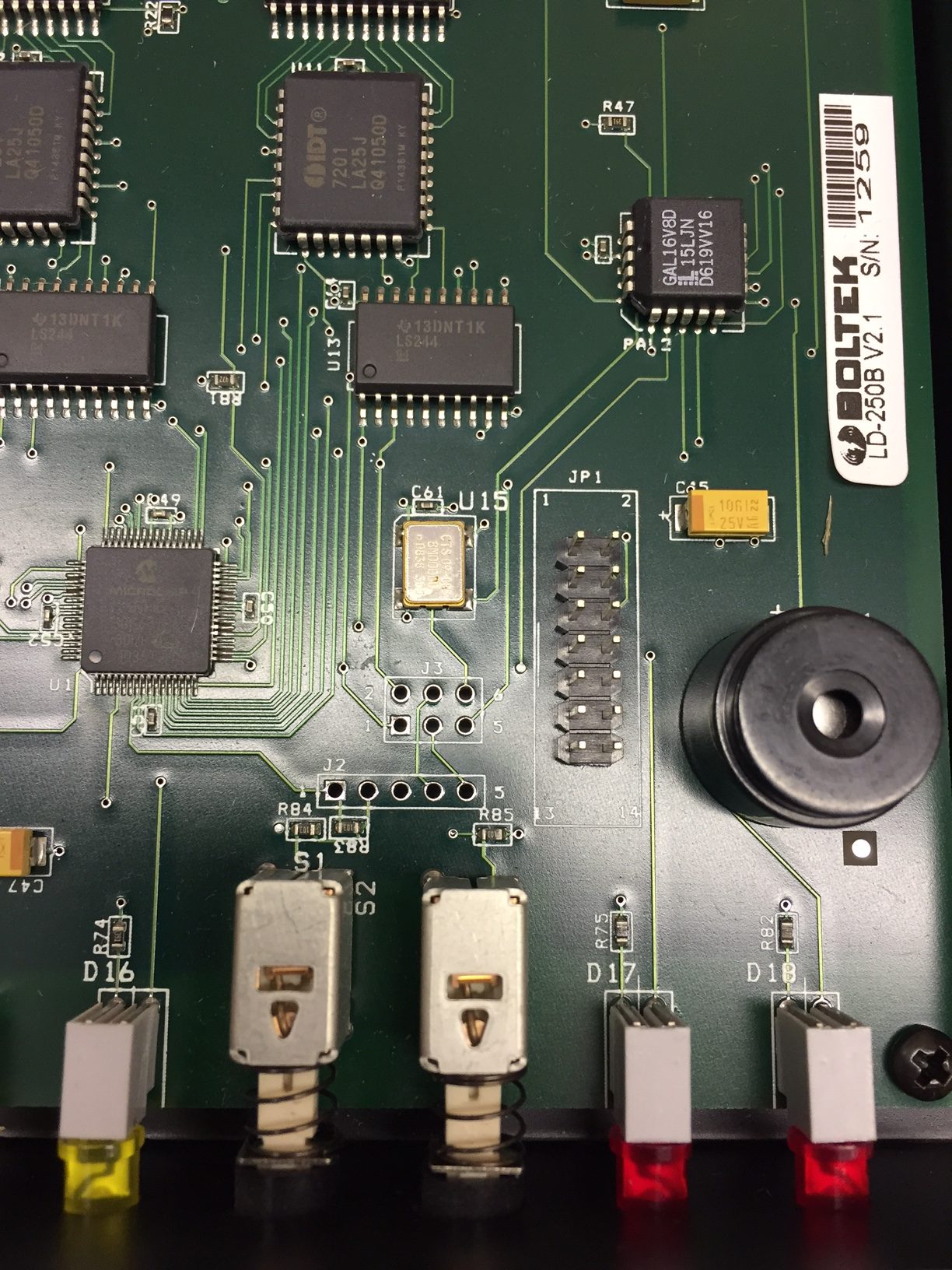
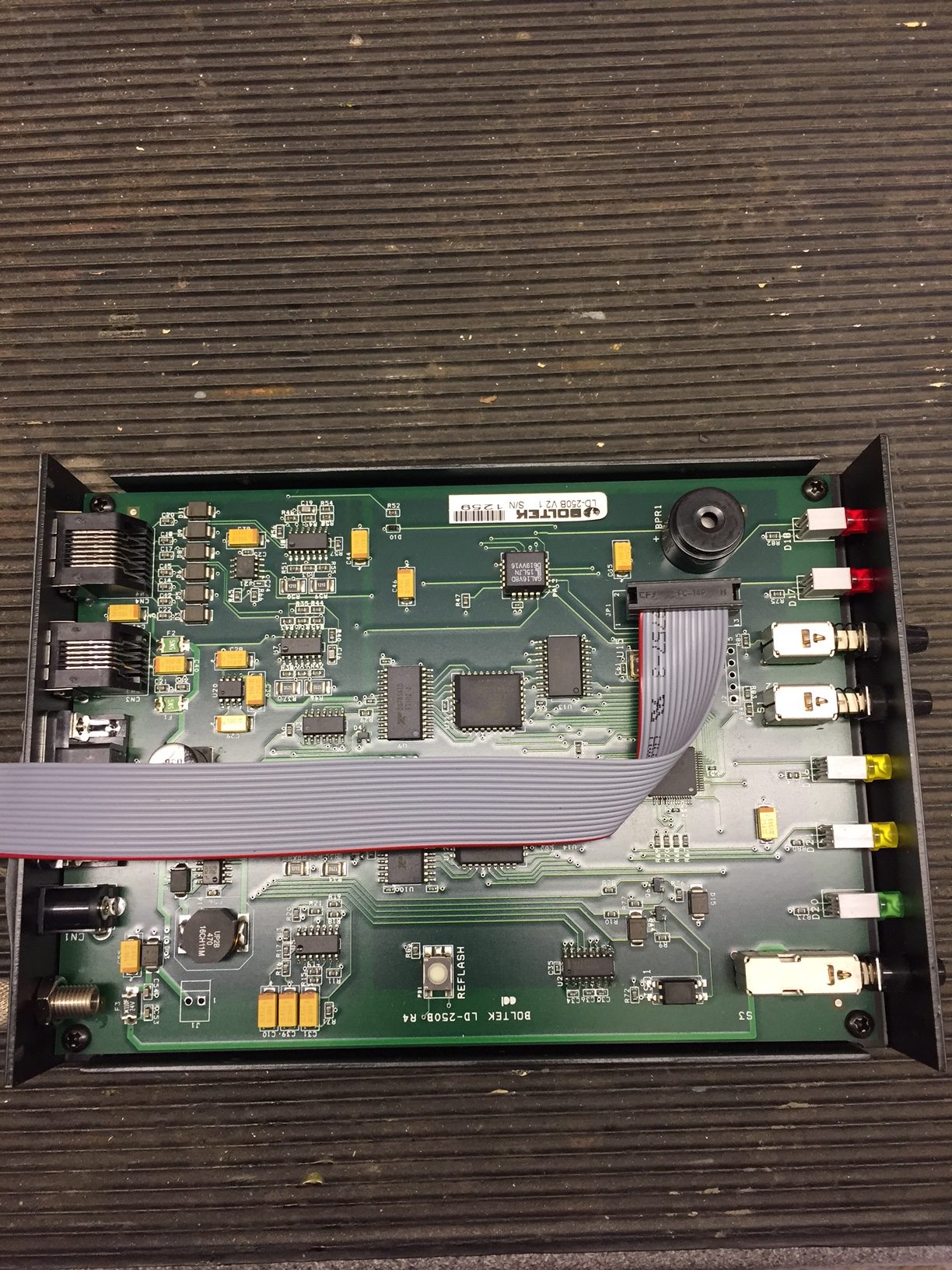
Opening the LD-250 the header JP1 is immediately obvious:
Using my multimeter, the header output pins linked to the front panel LED’s and the operating voltage was quickly found.
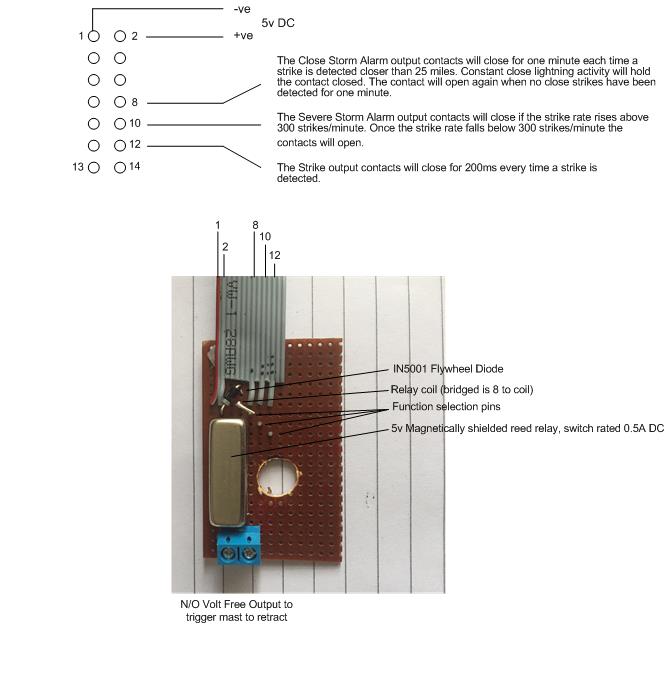
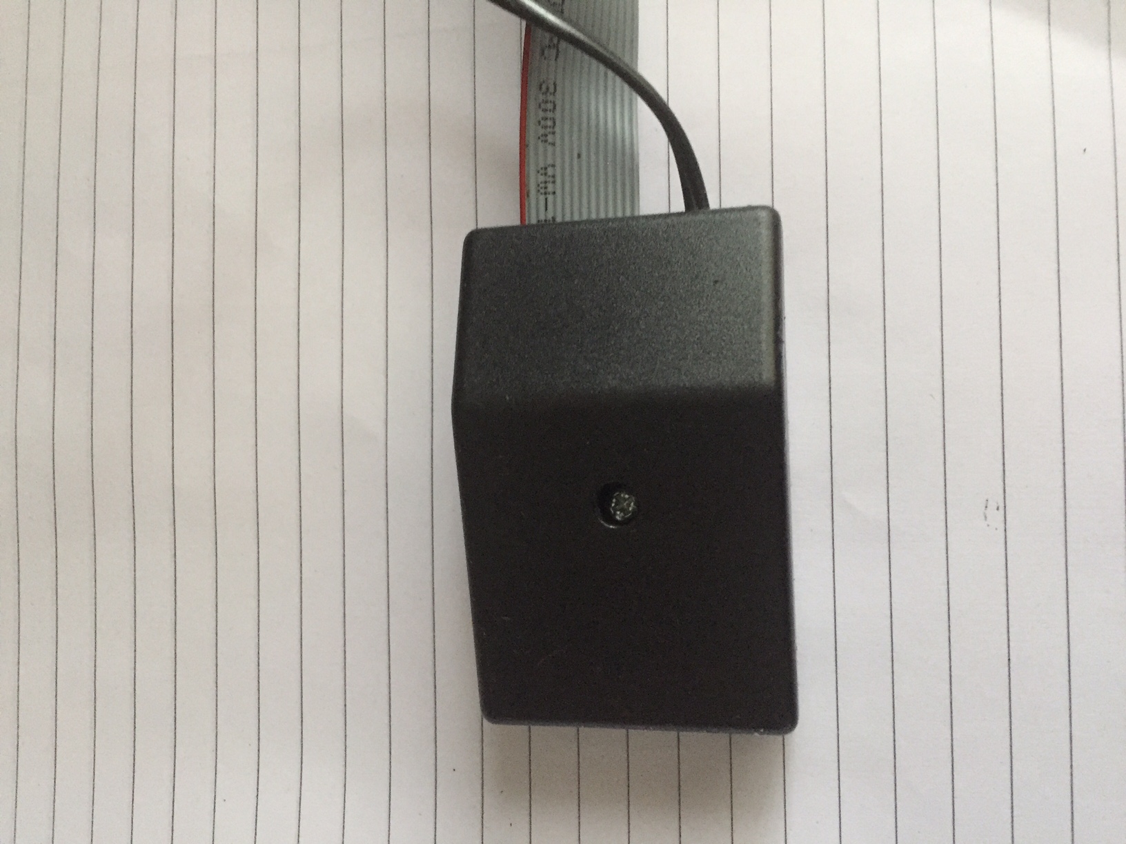
Using a spare strip of veroboard I mounted a magnetically shielded reed relay 5v, with flywheel diode across the coil, and the switched Normally Open reed output to a 2.54mm x 2 pitch connector, I also put veropins in the board so I can select which function I want the relay to operate on, should it be needed in the future.
The reed switch is used to switch 24v DC to an indicating LED and a a PLC input, the total load was measured at 21.49mA, well within the 500mA rating of the reed switch.
The module was placed in a small enclosure:
The ribbon cable was then plugged into JP1 inside the LD-250:
Switching on the Boltek performs a self test of the front LED’s and internal buzzer, as I have used the output from the ‘Close’ LED, the reed relay operated and the mast which was raised, automatically retracted.
All in all the project performs as expected and cost me £7 (enclosure was £2) saving me £58.95 on a factory unit.
Note – The infrastructure is now owned by nexfibre as a wholesaler, the only customer to date being Virgin Media, however, nexfibre are looking to open there network to other service providers….maybe Cityfibre!
This blog is about the roll out of Virgin Media fibre to the home in Chatteris from the civil works through to the delivery of a live service at my house and beyond.
To report insecure or damaged Virgin Media street cabinets: Call 0330 333 0444
26 October 17, Trench tarmacked and construction barriers removed.
5 November 17, I buried 20mm conduit from Toby to house wall and included a draw cord.
26 Nov 18, Cabinet AF0503 made live.
1 Feb 18, Virgin Postcode Checker now shows service available in my street.
4 Feb 18, Ordered VIVID 200 package for installation on Friday 23 Feb 18 between 13:00 – 16:00. Went through to the Virgin Media shop in Peterborough looking for some form of promotion or deal to reduce costs, this didn’t happen, in fact they suggested I could save money ordering in shop as they would waive the installation and F-Secure costs, this was incorrect as the online booking information has these as free, also they wanted £25 up front, £20 activation fee and £5 which would be returned once the service was active, online it is £20 only activation, so I booked online, as an aside, if I had ordered in the shop my statutory rights to cancel is reduced from 14 to 10 days protection which you get when booking online.
11 Feb 18, received two e-mails, the first containing e-sign contract, the other was what to expect on the day of installation.
16 Feb 18, received mobile call from Callum of the Virgin Media installation team wanting to come and install a microduct from the Toby to my house, fit the Omnibox and blow the fibre from the street cabinet to the Omnibox, this is done a week in advance of the engineers on the 23 Feb, I arranged for the following day to meet them as I was 180 miles away! (this part of the process was not known to me and came out of the blue, I assumed it would be a ‘one hit’ visit).
17 Feb 18, James from the installation team rang to cancel as Callums son had a fall and was needed at home, as the install is a two man job I returned his call and rearranged for Monday 19 Feb after 16:00.
19 Feb 18, James & Callum turned up at the appointed time to install the microduct, fibre and Omnibox.
The guys first photographed a laminated sheet showing my address, date and their names next to my open Toby, once this was done they threaded a black microduct pipe from the pavement Toby through the conduit I had previously laid to the house, the brown Omnibox was fixed to the wall with 4 screws and the microduct pipe clipped into place in the Omnibox, at the Toby a coupling was installed transitioning from the green microduct to the black microduct.
Transition coupling, black microduct to house, green microduct to street cabinet.
The distance was measured using a measuring wheel from my Toby to the street cabinet (72.5 m), while the measuring was going on, compressed air was blown down the microduct from the house, this caused the yellow protective cap to be blown off the end of the green microduct in the cabinet, identifying which tube out of many, as coming from my house.
In the cabinet a ‘fibre catcher’ was fitted, at the house end the fibre cassette containing 100m of fibre was fixed on a device which enabled the fibre to be blown into the duct until it was caught by the cabinet catcher.
At the cabinet, the fibre catcher was removed and a protective sleeve was fitted over the fibre and terminated in a connection, this connection was then plugged into a breakout panel in the cabinet.
We were the first in this cabinet.
At the house end, the surplus fibre from the cassette was wrapped within the Omnibox, the house end is pre terminated, once this was done, a reading was taken of light losses (-0.13db) to check they were in an acceptable range, the reading was photographed with the laminated sheet used earlier as proof of service in advance of the technical install scheduled on Friday 23 Feb 18.
Completed Omnibox after first visit ready for the optical media converter and splitter to be fitted.
23 Feb 18, Go Live Day – Engineer Sam arrived between the allotted time of 13:00 to 18:00 to start the installation.
He was quite happy that the hole through the wall into the lounge was already in, as was the dry lining that he could hang the Isolated Power Injector on.
First job was to push a peice of HFC cable though the wall from the Omnibox and put a connector on the end, this was connected to the Isolated Power Injector (IPI) Teleste IP1-G1)), which is mounted within an enclosure on the lounge wall (the screw holes of the enclosure and backplate fit a standard dry lining box), a short length of HFC cable from this goes to a 12v plug in PSU in order to back feed the external optical media converter with power.
The bottom IPI output is connected to a 2 way splitter (Technetix ESX-02), one leg goes to the router (a 3db attenuator was installed to balance the system), the other leg to the TV box.
As the TV box, Router and Optical media converter require power, three 240v sockets are required.
In the Omnibox, the HFC cable was terminated, and plugged into a DC passing port of the 4 way splitter (Amphenol Model ABS104TP), from the splitter this is plugged into the Vector Boostral 610 optical media converters output.
Once the external works was completed, the router and TV box were powered up and an Ethernet cable from the router to TV box was plugged in. The hardware went through three re-boots and software updates and I was good to go.
24 Feb 18, Netflix is suffering lip sync issues when viewed through the VM TV Box, also download speeds vary from 210Mb to 38Mb (wireless tests), it’s early days, so I hopefully this will stabilize soon.
25 Feb 18, Speed test using direct cabled connection to Virgin Media router (200Mb service ordered) :
25 Feb 18 @ 14.11
2 Mar 18, TalkTalk, my existing provider reduced my package ‘Fibre Large’ which is Fibre To The Cabinet’ (FTTC) by £26:25, on knowing I was thinking about leaving for Virgin Media, they did this by moving me to the ‘Faster Fibre Plan’.
I get the same package as before (TV, broadband and phone landline including line rental) for £31.75 per month, the download and upload speeds I’m getting are more than enough for my needs even when all the kids are home battering the broadband, also I keep my landline, Virgin Media have not yet enabled VOIP on the router which was another factor for me.
I called Virgin Media to cancel my arrangement (within the 14 day ‘cooling off’ period), they obviously asked why and I mentioned the main reason was cost and as an aside, that my wireless speeds were faster with TalkTalk rather than Virgin Media.
Perplexed by this, he transferred me to technical in a foreign land and they remotely checked the line and rebooted the router, then asked me to perform a router reset using a paperclip, which I did whilst they were on the phone. They assured me everything was working properly and I did a wireless speedtest and managed 136Mb download.
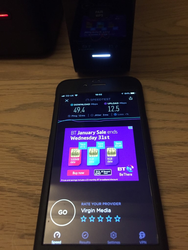
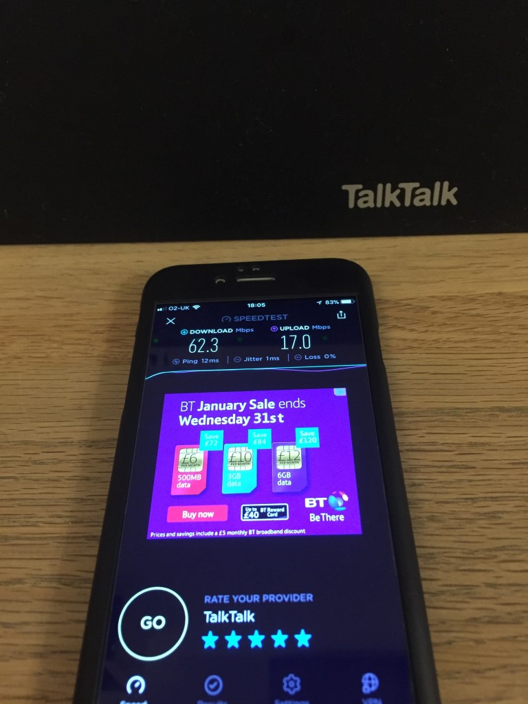
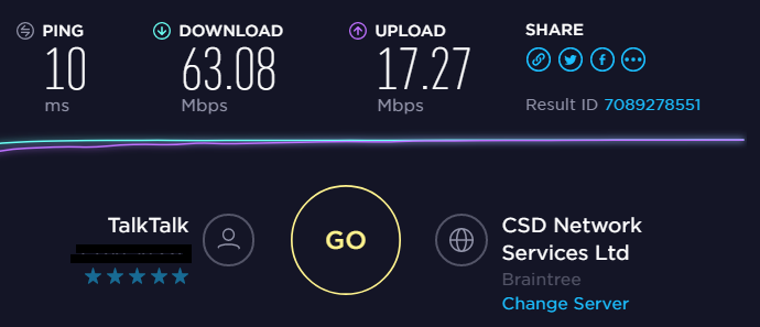
Checking later I took the following images of speed:
Download 49.4Mb, Upload 12.5 Mb from Virgin Media
Download 62.3Mb, Upload 17Mb from TalkTalk on 5GHz
The above results used OOKLA Speedtest on an iPhone 6, as the SSID on the Virgin Media router is the same for 2.4GHz and 5GHz I didn’t know which Wi-Fi band I was measuring, I was however, the only device was connected to it.
For balance I ran another TalkTalk test at 2.4GHz, and the readings came out at Download 41.7Mb, Upload 16.8Mb which wasn’t too shabby, especially as 7 wireless devices were connected.
I also ran a directly ethernet connected Virgin Media router test later with a laptop at 20:00hrs 2 March 18, and managed a download speed of 76.17Mb and upload of 10.3Mb, not brilliant for an upto 200Mb service which I was assured was working as it should.
The upshot is that I staying with TalkTalk meaning that I reluctantly terminated my arrangement with Virgin Media effective from 3 March 18.
8 Mar 18, Disconnected my Virgin Media as per the instructions which came in my returns packaging and boxed up the following way as requested:
Router;
TV box;
Remote control;
Two power supplies;
Leads for the above PSU’s;
Splitter and three CATV cables.
This was then taken to my local ‘Click & Collect’ store and it was winging it way back to Virgin Media at nill cost to me.
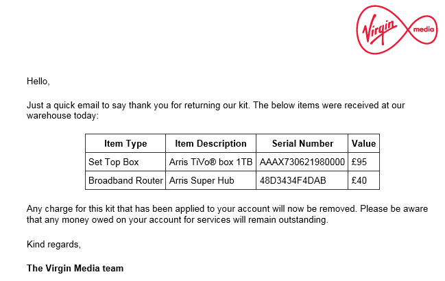
14 Mar 18, Text from VM to say the kit has been received and any charge for kit that might have been applied to my account will be credited, also received an e-mail:
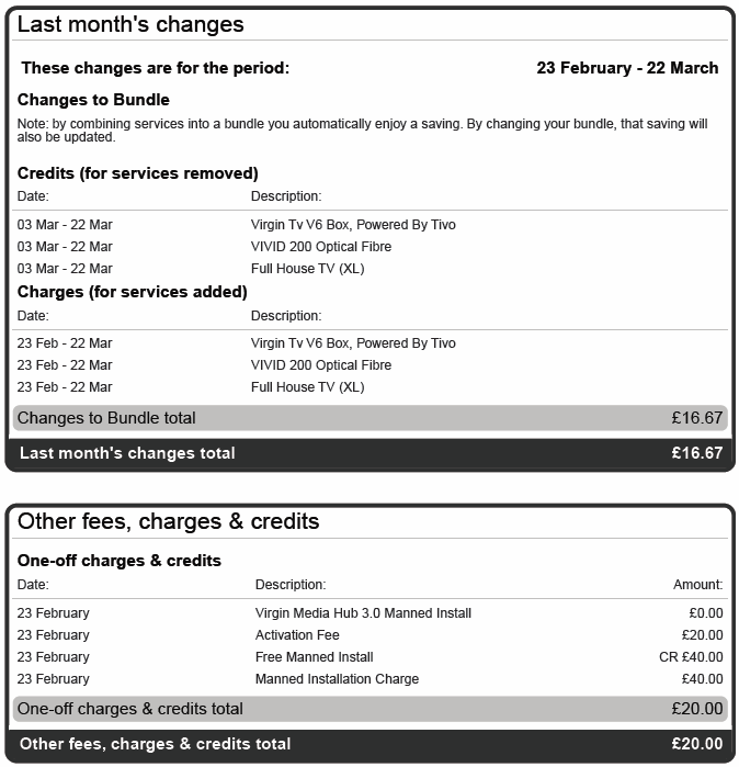
21 Mar 18, Received my first and last Virgin Media bill, this covers the week I had the service and the activation charge, total payable – £36.67.
30 Mar 18, Checking my bank statements and no money has been taken by Virgin Media so I cancelled the Direct Debit to them.
1 Apr 18, Received e-mail from Virgin Media thanking me for joining them and asking me to complete a short survey which I did even though I’m no longer a customer.
4 Apr 18, Virgin Media activity showed on my bank statement ( – £36.76 then +£36.67), contacted VM and they said I do not have to pay anything as I cancelled within 14 days.
11 Apr 18, Text from Virgin Media to call 0800 052 2630 in order to clear my outstanding balance, talked to Kirsten and she saw the error that cancelling within 14 days shouldn’t have triggered a bill, so she added a small credit to my account in order to cancel the debt on the system.
25 May 18, Received letter from Virgin regarding GDPR.
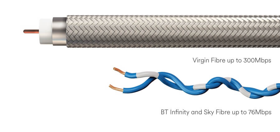
Hybrid Fibre-Coaxial cable and below that a fibre optic connector
Phased civils started in June 2017 and by 4 January 2018 first subscriber activated.
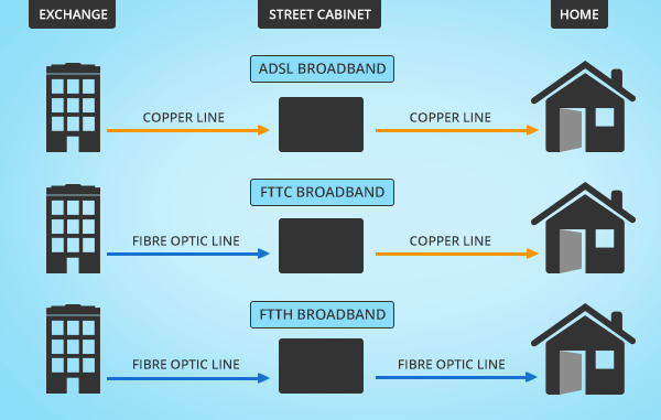
I currently use TalkTalk Fibre to the Cabinet, this the same as BT Infinity, SKY, Plusnet etc, this means a fibre optic cable is brought from the local exchange to a street cabinet, from this the existing telephone copper cable is used for broadband and phone, depending how close you are to the cabinet will determine how fast your broadband is, in may case, I get a maximum speed of 62.79Mbps download, 17.34Mbps Upload and a Ping time of 17.34ms which is probably the best I can get (using Speedtest 15/11/17 @ 18:00).
Diagram showing how Fibre To The Home (FTTH) is just that.
I was delighted when I saw that the Virgin Media cable enabling works was scheduled for installation via Roadworks.org, bringing up to 300Mb speeds to Chatteris, this will give people an option, rather than be tied to telephone line provided services, so I thought I’d start this blog.
This speed test was done on the 25 Feb 18 @ 14.14 by directly connecting a cable to the TalkTalk router to compare FTTC with Virgin Media FTTH:
Not to shabby performance for over copper wires.
Infrastructure Process
The infrastructure in my area was due to start on 4 August 17, expecting to last until the 14 August and I registered my interest in advance using Cable My Street.
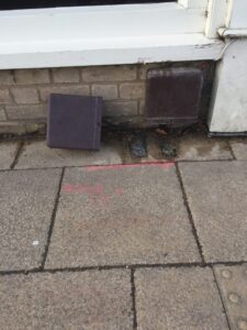
My roads infrastructure work started on the 23 October 18 and was carried out very swiftly and with minimal mess considering the civil work required, the works was undertaken during school holidays to minimise any disruption, the crew were respectful of any request to get on and off the drive, also in my case I wanted the ‘Toby’ to be in a particular position, this wasn’t a problem and on the pictures below you can see the original point marking has been crossed out, and the new position marked as a red box.
VM installing my Toby
Time lapse video of Virgin Media installing FTTH infrastructure.
Details on how the Virgin Media infrastructure is installed (for developers but a great resource) is HERE (large file) and a general guide used for another town scheme is HERE.
The system we are getting from Virgin uses RF over Glass, with the infrastructure being installed by John Henry Group. This comprises of a fibre optic cable laid in a trench which is blown through a microduct tube from the nearest cabinet to the home after your order is placed.
I’ve included a YouTube video by EJC to show hows its done when the cameras are rolling.
Microbore tube showing fibre optic cable
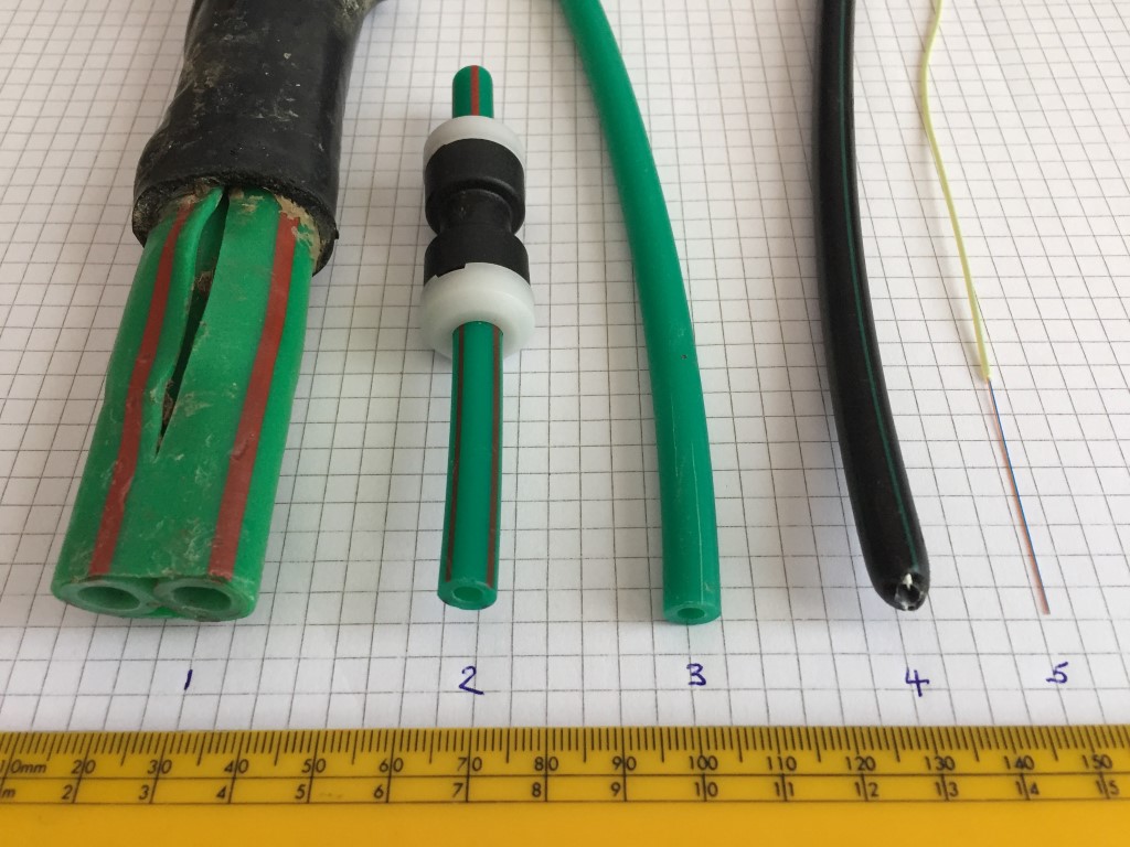
The wrapped Red and Green double tube is installed from the VMVH1 hub cabinets to the Level 3 (L3) street cabinets via solid ducts. Each tube has an Outside Diameter (OD) is 12mm one tube is used to transport 24 core fibre optic cable, the other bore is spare.
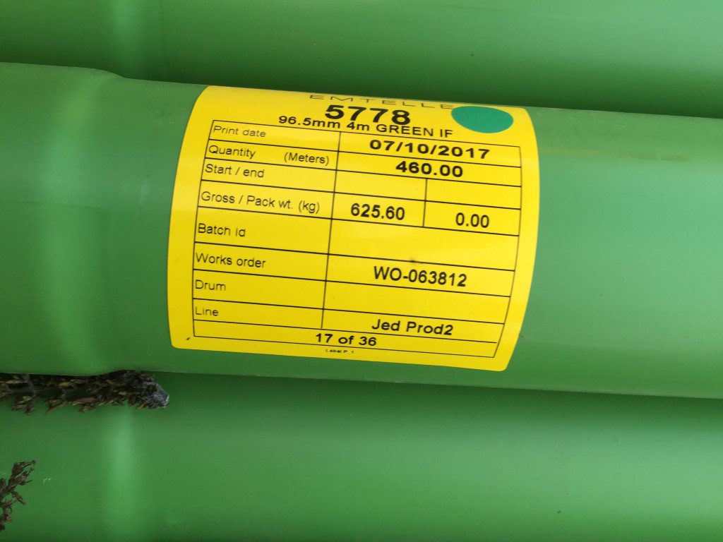
Duct for transporting double Green/Red stripped microduct.
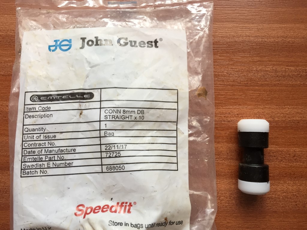
2. The single Red and Green has an OD of 8mm and carries 12 core fibre optic cable from the L3 cabinet to the Level 4 (L4) distribution board. The L3 cabinets are identified by having only two letter and two numbers stenciled on them.
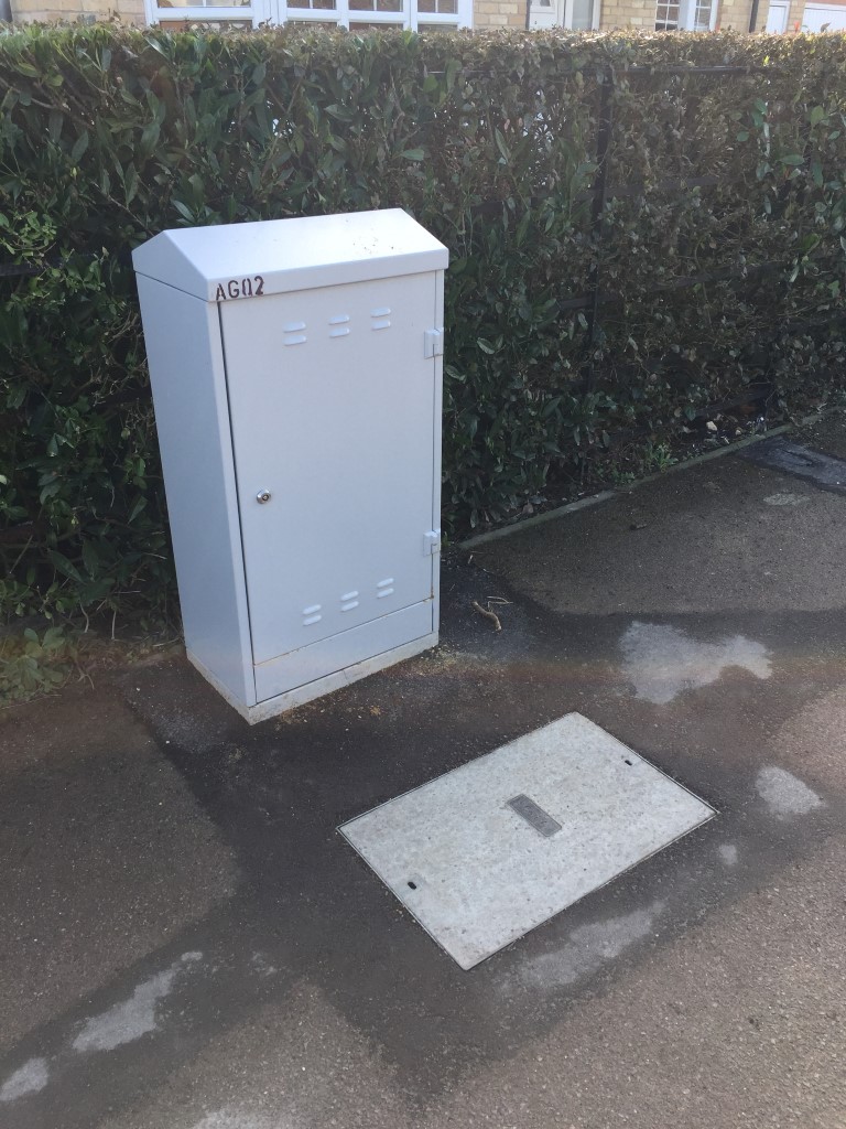
Level 3 cabinet in St Martins Road
3. The Green microbore is 8mm OD and is ran from the L4 cabinet to each ‘Toby’ outside the property.
4. Black microbore is the same dimensions as the Green microbore and is used from the Toby at the pavement to the house Omnibox.
5. 1.1mm diameter single mode fibre optical cable containing two fibres, I stripped the fibre back in the above picture, from the factory the fibre is pre-terminated.
Connection method used in the street cabinet after the fibre has been blown in.
8mm straight couplings used to connect microducts.
The image below shows the microduct couplings in use within a pavement trench. Top picture taken at the junction of Dock Road and Bridges Street, bottom picture taken by the library shows a larger 12mm OD striped microduct.
Larger size microduct and coupling, (possibly for a multicore fibre, rather than a single fibre?).
The marker tape which is put over the buried Virgin Media infrastructure and serves two purposes, the first is to allow detection using a Cable Avoidance Tool (CAT), the marker tape has two metal wires bonded to it, so the route of the tape can be found and traced from the surface without excavation, the second purpose is to warn that you are about to unearth or hit cables should you be digging.
Nice swerve around 🙂
VMSDI Level 4 Open Cabinet Picture – undergoing second-fix.
VMSD1i – 535 W x 985 H x 330 D Distribution Cabinet 1 per 48 Homes (when used as L4)1 per 512 Homes (When used as L3) – Cabinet found locked in the open position 5/11/17
Click Map Pin on the corner of Ash Grove and High Street for more images of cabinet AF0113.
Great guy second fixing AG01 which is a Level 3 cabinet.
One of the towns two VMVH1 Nodal Cabinets
Newly installed VMVH1 – 1800 W x 1700 H x 650 D Nodal Cabinet (Virtual Hub)1 per 3000 Homes Approx. The yellow temporary cover was used to protect the hole before the VMVH1 cabinet was installed.
Inside VMVH1 supply pillar
Permission asked of road workers to take pictures, cabinet unlocked and open 18 Nov 17
Within the distribution board above is a smart RCD from Tii-Tech which is rather clever as it performs regular operational self tests to avoid the need for a person to visit the cabinet to do them.
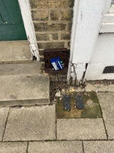
End of Line Termination Boxes
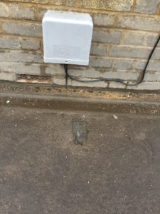
From the street termination box, a microduct coupling is used to extend the duct from the street cabinet to your outside wall, the fibre once blown through is connected to a media converter within the externally mounted Omnibox
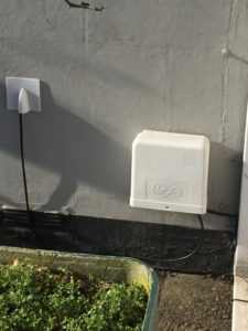
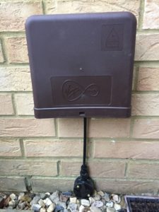
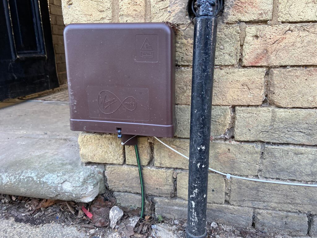
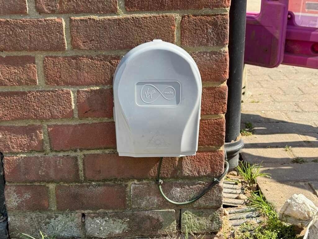
Showing the three different colours of Onmibox used in Chatteris, the last one is mine.
The media converter changes the fibres optical pulses of light into electrical data which a coaxial cable then takes to the Super Hub 3 Router and connectivity to the internet.
Cassette of single mode fibre, pre-terminated, up to 500m in increments of 25m are used dedpending on the distance from home to cabinet (25m, 50m, 75m, 100m, 125m, 150,m 300m & 500m).
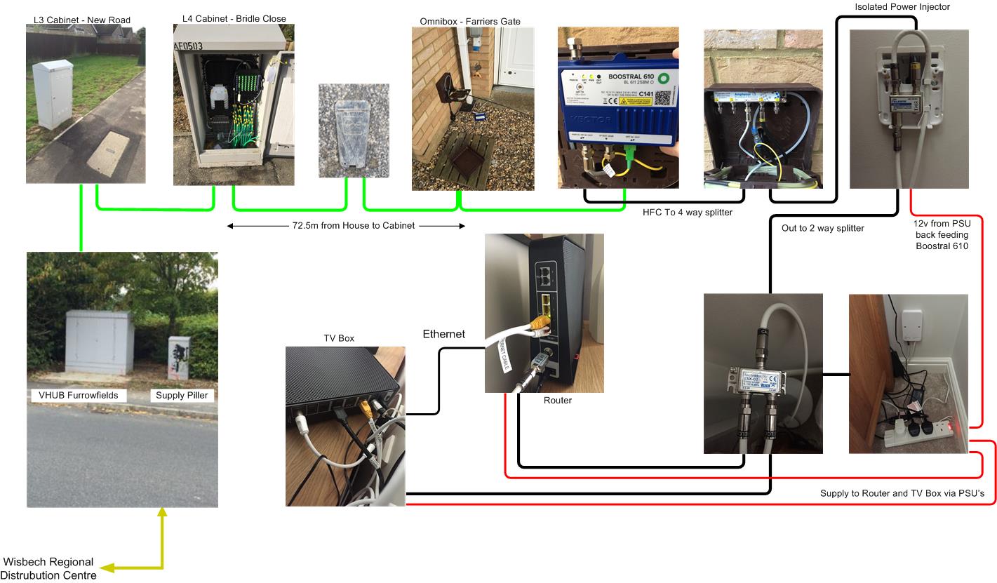
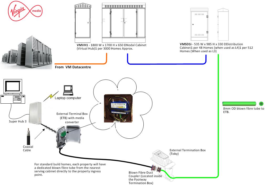
This configuration will give data transfer speeds of up to 300Mbps, a basic outline of how it connects together is below, the VM Datacentre is in Wisbech and Chatteris is fed by a direct fiber from their:
Data centre to house
In advance of Virgin installing the infrastructure in the street I have put a conduit through the wall into a dry lining box with a blank please and installed a length of 20mm flexible conduit from the pavement Toby to the house wall, bit premature, but hey ho 🙂
Links to latest and archived Planning Permissions for Chatteris containing Virgin Media infrastructure works (remedial works have been excluded) :
Remedial works undertaken to the ducting infrastructure, pavement trenching made good and raised Toby’s lowered.
Update -11 Jan 2021
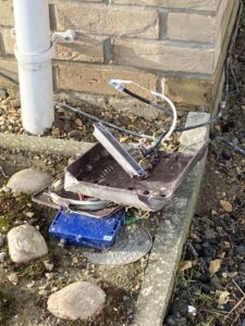
Damage to kit and check out how deep that fiber is as it crosses the lawn, so easy to damage!
The depth of the fiber pipe is about 40mm, so easy to damage if doing lawn maintenance!
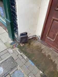
Unfortunately the Omnibox is easily damaged/abused.
Update 1 July 2021
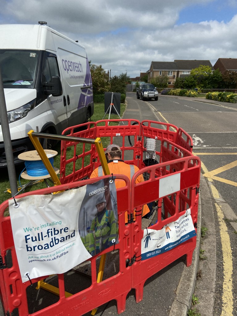
Openreach are installing the infrastructure for Ultra Fast Broadband, Virgin no longer has the monopoly on decent speeds which can only be good for the consumer.
How things change since 2018 when Virgin Media went live in Chatteris, the choice of Fibre to the Premises Ultrafast broadband Internet Service Providers is now a lot larger using Openreach fibre infrstructure.
The new kid on the block, (2023), is Netomnia with there own dedicated infrastructure and competitive pricing is displacing existing Virgin Media customers:
Who knows what’s next?
Update 2024 – Nexfibre
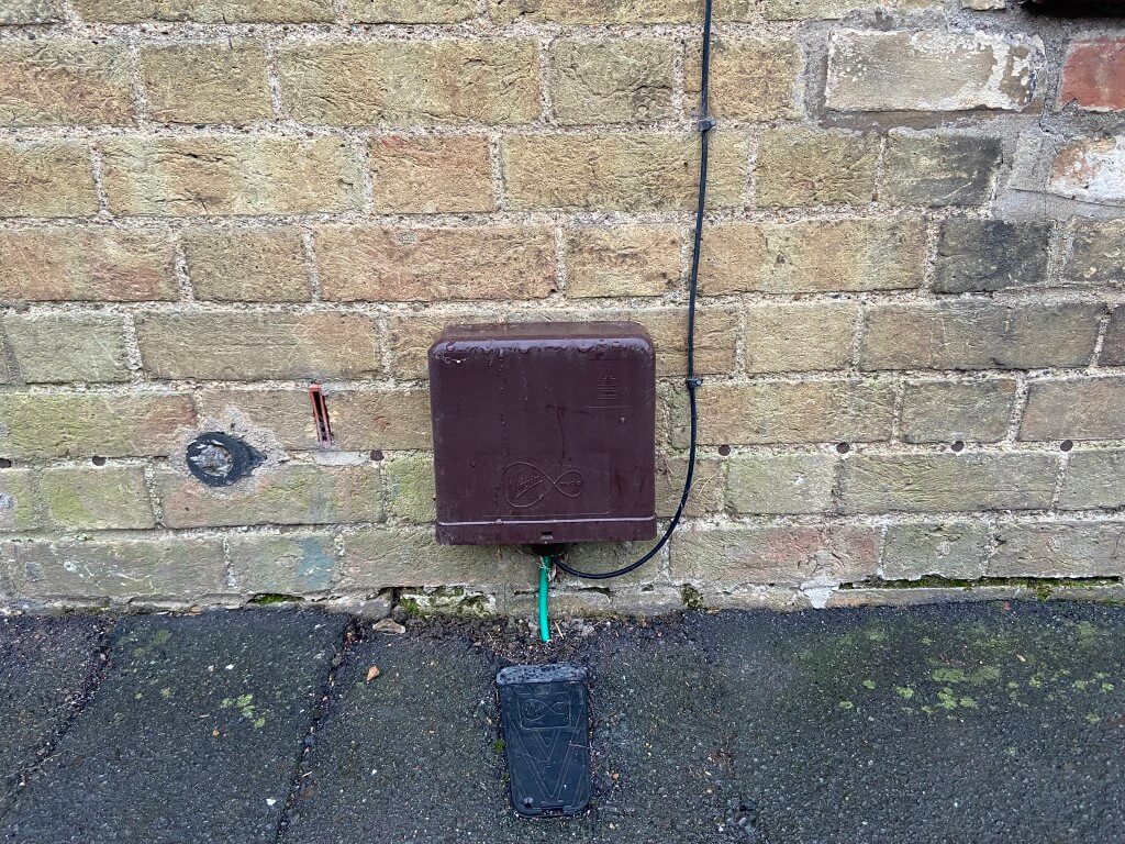
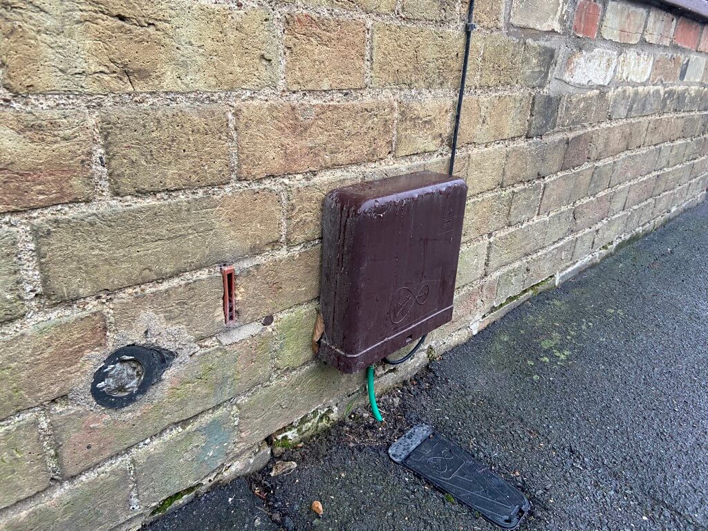
Virgin Media O2 are modifying their home network connection by removing the co-ax cable element and media converter active component, (blue box in the above picture), for fiber directly into the house. Due to the removal of the media converter, the external box can be a lower profile design.
The modification will now enable comparable performance with other internet providers.
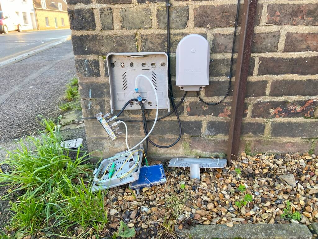
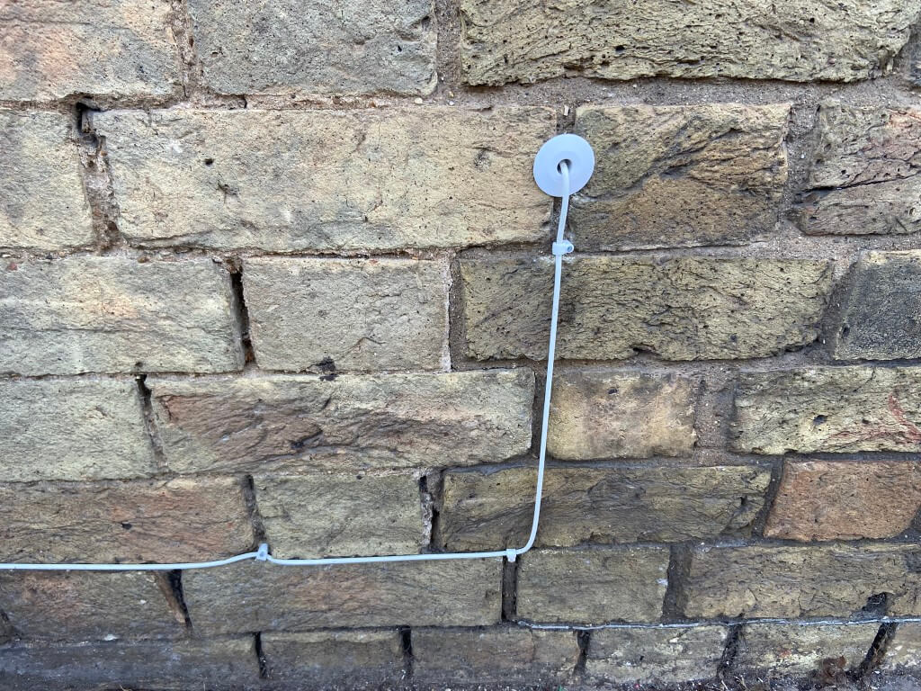
One thing I did notice on my walkabouts is the installer appears to have removed the outer UV protective fibre sheath and the cable clipping looks to have bend the fibre outside its minimum radius on this installation.
Not sure if the white inner is UV stabilized, but I thought it an odd thing to do and generally looks a Friday job.
16 June 2025
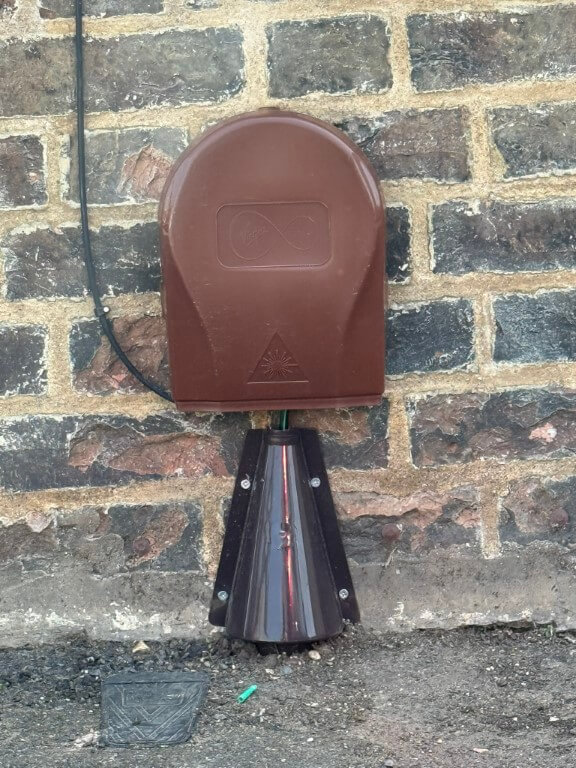
Spotted these new style external customer splice points, quite funky.
Link back to Radio Mast Automation – HERE where the EASY RL-V23 unit can just be seen attached to the lid of the mast controller.
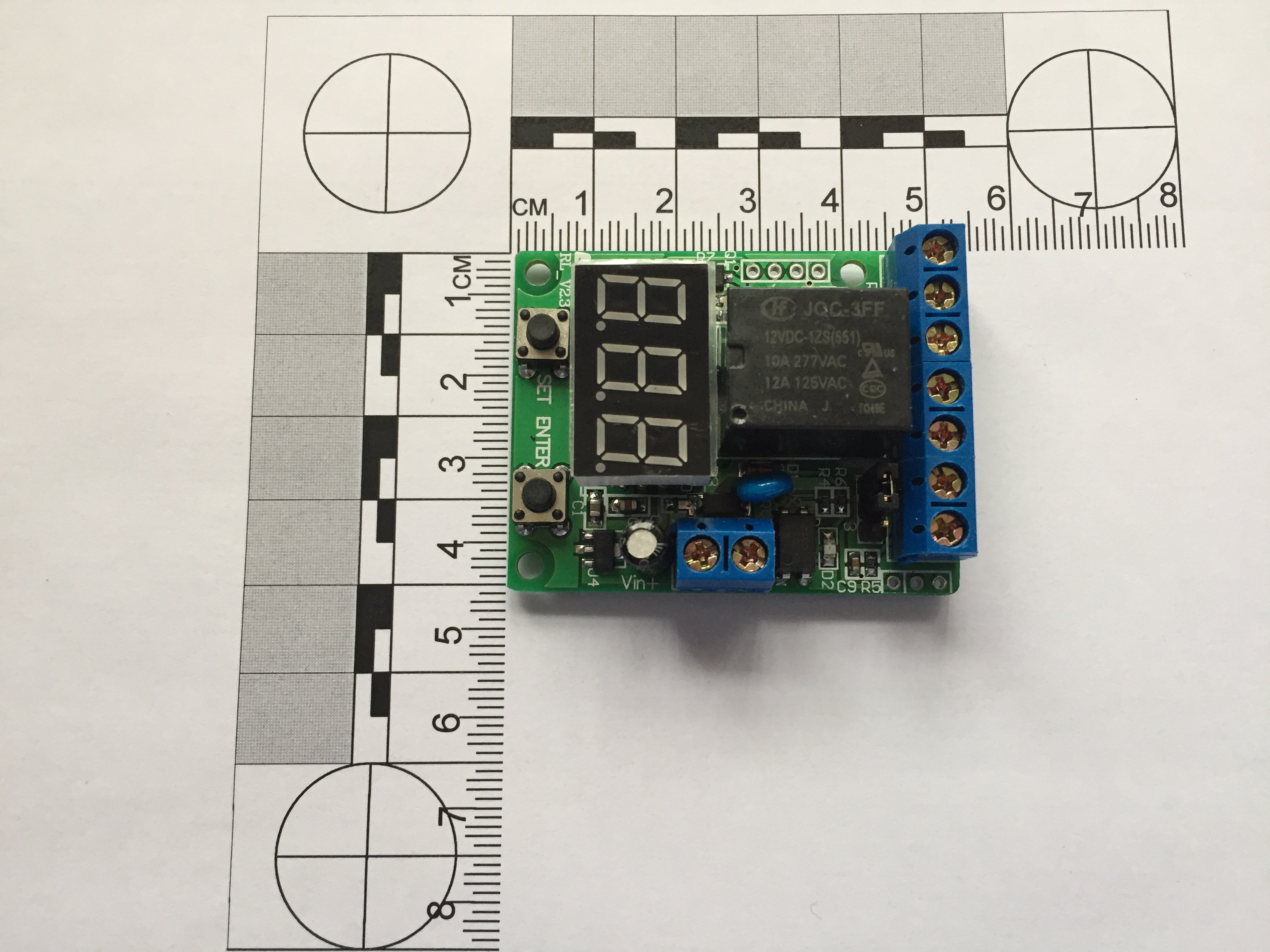
EASY Voltage Unit
The above module was from eBay and advertised as a ’12V Voltage Control /Delay Switch /OverVoltage /Under Voltage Protection Module’ for £4.92.
This unit is incredibly versatile, and I’ve included the operating instructions in the blog.
I have used this module to monitor the charging voltage of a battery, once the voltage has reached a pre-set value, an output will trigger to stop the charger.
Operating modes:
P-1: Timer ( 1-999 S / 1-999 Min)
P-2: Delay timer ( 1-999 S / 1-999 Min)
P-3: Voltage control relay ( control the load on/off)
P-4: Voltage control Timer- A (release first)
P-5: Voltage control Timer- B (close first)
P-6: Voltage range control relay
P-7: Voltage range control Timer
P-8: Set display off
Timing Range: 0-999 seconds or 0-999 minutes (0.1s-999s optional)
Voltmeter display range: DC 0-99.9 V
Voltage detection error: ± 0.1V
Operating Power: DC10~16V (5V,24V optional)
Relay parameters:
Coil Voltage: DC 12V (5V,24V optional)
A set of conversion (normally open and normally closed)
Contact load: 10A/277V AC or 10A/30V DC
Contact resistance: ≤ 100mΩ (1A 6VDC)
Mechanical durability: 10 millions
Electricity durability: > 100,000 (10A-250VAC)
Operating Temperature: -40 ~ 85℃
External signal input: (5~ 12V) or passive switch (9 levels delay time can be set)
Timer mode can set the relay contact close and release time, the implementation of a single timing loop
In voltage control mode, can preset upper and lower voltage values limits
Set display shut, the minimum current values are 6mA/12V (delay released)
The pre-set parameters can be saved after power off.
2 Operating modes:
Connect to power, LED digital tube displays words “E-A-Z-Y-t” in turn, system enter into the selection state, the initial mode selection is displayed as “P-0”, press the “SET” button to select “P-1~P-8” mode, press “ENTER” to enter the corresponding mode.while any mode running, press the “ENTER” button for 3 seconds, system will return to the mode selection state.
Press the “SET” and “ENTER” button to connect the power, the controller will be restored to factory settings.
2.1 Timer mode (P-1)
Press the “SET” button to select “P-1”, controller system will enter into the timer mode.
“P-1”/ “P-2”: 1-999 seconds /minute can be set.
Cyclic run:
In the timer mode, the user can set the relay’s close time T1 and the release time T2,such as setting T1 for 3 seconds, T2 for 7 seconds, the relay will be closed for three seconds then release for 7 seconds, cyclic run.
User also can set cyclic times.
When you have set the values of the T1 and T2 , the system saved the settings, the next time system will be loaded automatically T1 time to wait running.
Timer:
If you set T1 with a specified time, set T2 (release time) with 0, the relay will stop after the timer run T1 time, no longer running, it can be used as a timer, with running time end, the normally open contact of relay release, then press the “ENTER” button, the system re-start the timer for T1 time.
In timer state, you can use external switch or pulse signal input Interface on controller to start the timer (trigger).
Timer setting steps:
1) For the first time of set , select “P-1” time relay mode, LED digital tube display” 000 “;
2) Press the “SET” button, system will enter into the T1 time values settings first, the digital LED that wait for set flashing with 1Hz frequency, press “ENTER” to select the number of values, press the “SET” button for three times to enter the T2 time values settings, and cyclic times, press the “SET” button to exit the set state, the system waits to press “ENTER” button to start running.
3) In the time setting state ,time values’ unit can be switched to minutes unit or second unit, press the “SET” button to enter the time set by state (set LED digital tube flashing) ,at this time Press the “SET” button for 3 seconds to release ,the LED digital tube will light the right decimal points, it means that timing values with minutes unit, if the decimal point dose not light, it means that timing values with seconds unit.
4) After setting is completed, press the “SET” button to exit the setting state, press “ENTER” to start timing, if timing values is set with second unit, seconds values will display with countdown form. If timing values is set with minute unit, the right decimal point flashing with 1Hz frequency, means the countdown is running. While timer is running, the normally open contact of relay connected, the normally closed contact of relay disconnect, press the “ENTER” to halt run, press the “ENTER” for three seconds to return mode selection state “P-0”.
2.2 Delay timer (P-2)
The Setting method of “P- 2” is the same as “P- 1”, in the mode of “P-2”, the relay will first execute release of T1 time then closed with T2 time.
2.3 Voltage control relay mode (P-3)
In mode selection state(“P-0”), press the “SET” button to select “P-3”, then press the “ENTER” to enter the voltage comparison control mode, the controller will detect voltage from “VOL” Interface and display values (DC 0-99.9V),it also can be used as a DC voltmeter ,the default initial run state relay contact is closed (normally closed contact is disconnected, normally open switch on), press the “SET “button to set the three bit values, the LED digital tube is set to flashing with1Hz frequency, first to be set upper limit voltage values , press the “SET” button three times, lower limit values of voltage to be set,press the “ENTER” button to increase the number of values, the lower limit voltage can not exceeds the upper limit, press the “SET” button to make digital tube is no longer flashing, this time system enter into voltage control mode , the controller detects DC voltage from external input Interface , when voltage detection exceed the upper limit of the pre-set, the relay close (normally open contact connect ,normally closed disconnect), until the voltage drops below the lower limit pre-set, the relay will release (normally closed contact connect , normally open contact disconnect).
In voltage control condition, press the “SET” button for three seconds then release the button, the contact of relay state will be reversed. such as: the relay close when detect voltage below the lower limit voltage.
If the pre-set voltage upper and lower limits set to the same, such as 12.0V, when controller detect volts at 12.0 fluctuations may cause the relay contact frequent action, we recommend to set the voltage to maintain the difference between the upper and lower limits.
Note: The detection voltage terminal must connected reliable, have not loose wiring around the circuit board insulation ,may lead to the induced voltage detection values is not accurate.
2.4 Voltage control Timer mode (P-4 / P-5)
“P-4” or “P-5” mode is composed of “P-1” and “P-3” or “P-2” and “P-3”.When the system switched to “P-4” from “P-1”or“P-2”,it will enter the voltage control timer mode, the controller will detect voltage from “VOL” Interface ,when detect voltage exceed the upper limit of the pre-set voltage, the timer will start , until the volts drops below the lower limit pre-set , the timer stop.
If you set time in “P-1” mode previous, then enter the “P-4” mode , the relay will close with timer first ,then release, If you set time in “P-2” mode previous, then enter the “P-4” mode ,the relay release with timing then closed.
The difference between “P-4” and “P-5” is the relay’s Initial state, “P-4” mode relay release first, but “P-5” mode relay close first.
Press the button of “SET” last for 3 seconds, the timer will start in the case of the voltage is below the lower limit. the setting method of limit pre-set voltage, please refer to section 2.3.
For example:
(1) In P-2 mode , set T1 005, T2 000, then enter P-4 mode , voltage detection exceed the upper limit of the pre-set the relay will close after 5 seconds, voltage drops below the lower limit pre-set the relay release Immediately.
(2) In P-1 mode , set T1 005, T2 000, then enter P-5 mode, voltage below the lower limit pre-set the relay close immediately, voltage detection exceed the upper limit of the pre-set the relay will release after delay 5 seconds.
Voltage control logic can be reversed with press SET key for 3 seconds.
2.5 Voltage range control relay (P-6)
If the voltage controller detects exceed the upper limit of the pre-set voltage, or the voltage drops below the lower limit pre-set voltage, the relay will close, otherwise the relay release between upper limit and lower limit range. Press the button of “SET” last for 3 seconds, the relay reversed. The relay will close between upper limit and lower limit.
2.6 Voltage range control Timer (P-7)
If the voltage controller detects exceed the upper limit of the pre-set voltage, or the voltage drops below the lower limit pre-set voltage, the relay will run follow time relay mode that has been set in P-1 or P-1 mode previous.
When voltage values between the upper limit and lower limit range, press SET key for 3 seconds, relay reversed between close and release (ON/OFF).
For example:
In P-1 mode, set T1 005, T2 000, then enter P-7 mode, set relay close between upper limit and lower limit range. When voltage below lower limit or exceed upper limit, the relay will release after 5 seconds.
2.7 Set display shut (P-8)
The display shows “d-0” means keep bright, you can press the button of “SET” set 0-9 minutes for display shut.
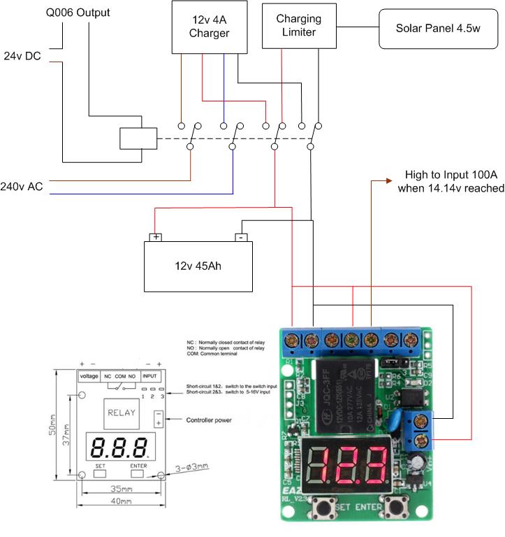
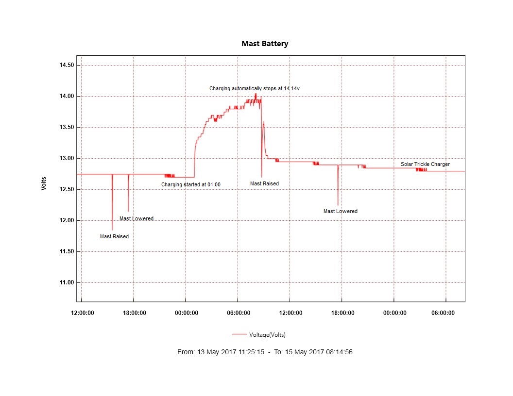
Graph showing operation of raise and lower including the automatic charging cycle.
Mast and Wire Rope protection & lubrication system
I wanted a quick and easy way of applying protective lubricant to the wire rope which raises and lowers my mast, my first effort involved a paint brush and a tin of grease and I thought then that their must be a better method, both in terms of speed and effective application.
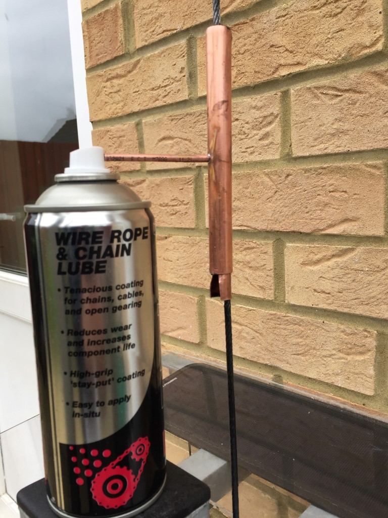
The option I chose was to use a spray wire rope and chain lube in conjuction with a home brew applicator.
The FORCE spray lube costs £6.25 for 400ml from eBay, the details of product are:
A long lasting highly tenacious spray grease which reduces wear and increases chain life.
High grip, anti fling properties provide long lasting, high depth lubrication and protection.
Penetrates inner rollers and resists the highest shock loads.
Ideal for chains, cables, wire ropes, fork lift chains, open gears and tail lift assemblies.
Reistant to weather and salt, provides high resistance to wash off.
‘O’ Ring Safe unlike other greases!
Parts
1 off 10mm copper pipe 150mm in length
1 off 15mm copper pipe 135mm in length
1 off 4mm copper pipe 60mm in length
1 off 12mm panel grommet
Construction
The 10mm pipe had a 5mm slot cut down the complete length to allow the pipe to fit over the wire rope, at the base of the 10mm pipe I ‘flared’ this to 14mm.
The 15mm pipe was cut at one end with a roller type pipe cutter (pipe slice) and this formed a nice curved lip, at the other end I used a hacksaw, this pipe also had a 5mm slot cut down its length, for the cutting of the slots I used a dremel with a mini abrasive disc.
As the spray gease doesn’t come with extension tubes, I decided to use 4mm copper pipe (the 2mm inside pipe bore is perfect to slide over the spray cap nozzle), this was soldered half way up the 15mm pipe, this pipe enters directly opposite the cut slot. To act as a ‘key-way’ it protudes into the pipe by 1mm.
A 12mm panel grommet is cut to fit inside the 10mm pipe.
Operation
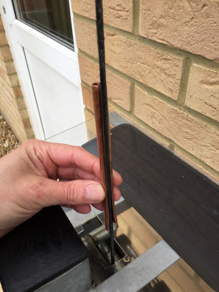
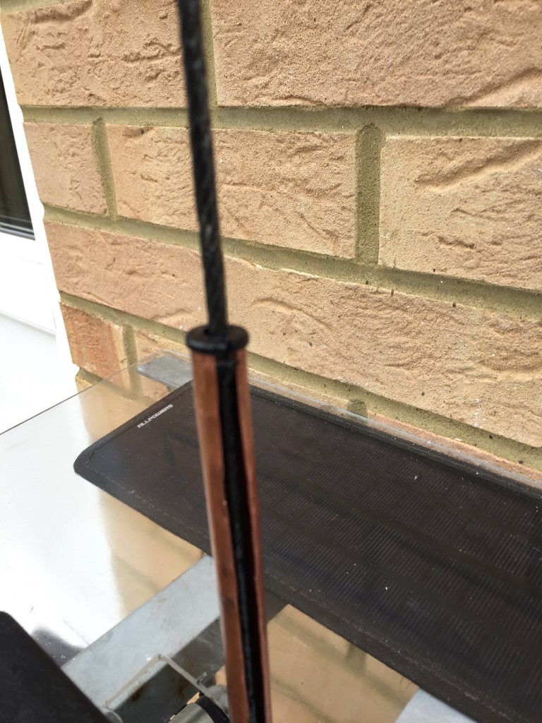
The 10mm pipe is slid over the cable with the flared section at the bottom:
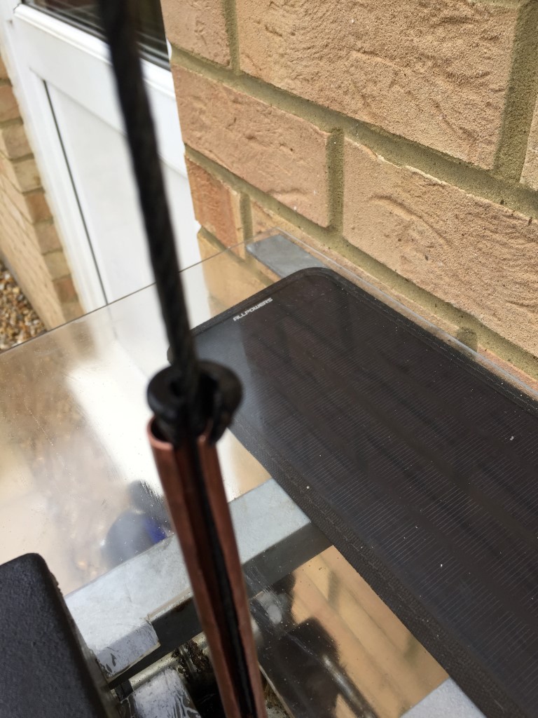
The grommet is installed at the top:
The 15mm pipe is now slid over the cable above the 10mm pipe and rotated so the grease inlet is inline with the slot in the 10mm pipe:
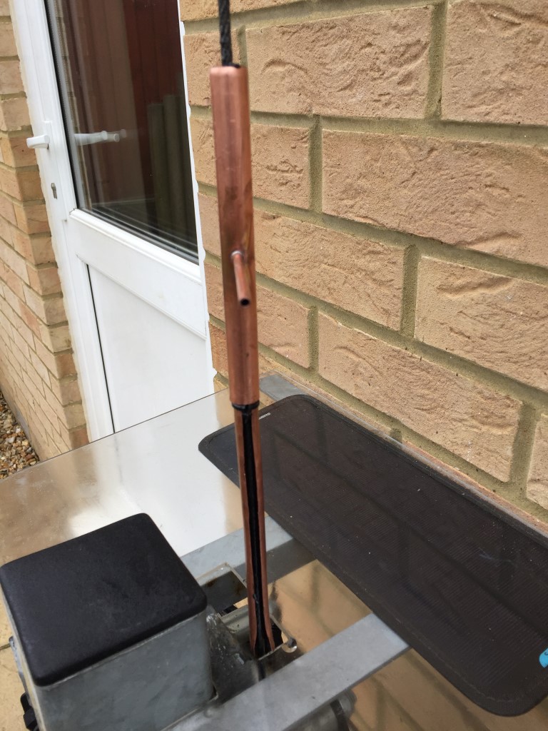
Noting the alignment, the 10mm pipe is pushed inside the 15mm pipe, the 4mm pipe protuding inside the 15mm pipe ensures the 10mm pipe can only fully slide in if the slot aligns, The lip on the 15mm pipe holds the grommet in place:
The finished product works quite well and gives an even coating to the wire rope, the length of the 4mm pipe was to allow the spray can to rest on a bracket, so I simply raise the mast and hold the spray button down 🙂
Mast Lubrication
For the mast lubrication I use Lithium Grease, this is easy to apply from the spray can and is designed for metal to metal contact, a typical lubrication application for my mast with a rising section of 5.4m is 200ml.
The Hazard Data sheet for WD40LG White Lithium Grease.
A blog about stuff that interests me or I have done.
We use cookies on our website to give you the most relevant experience by remembering your preferences and repeat visits. By clicking “Accept All”, you consent to the use of ALL the cookies. However, you may visit "Cookie Settings" to provide a controlled consent.
This website uses cookies to improve your experience while you navigate through the website. Out of these, the cookies that are categorized as necessary are stored on your browser as they are essential for the working of basic functionalities of the website. We also use third-party cookies that help us analyze and understand how you use this website. These cookies will be stored in your browser only with your consent. You also have the option to opt-out of these cookies. But opting out of some of these cookies may affect your browsing experience.
Necessary cookies are absolutely essential for the website to function properly. These cookies ensure basic functionalities and security features of the website, anonymously.
Cookie
Duration
Description
_GRECAPTCHA
5 months 27 days
This cookie is set by the Google recaptcha service to identify bots to protect the website against malicious spam attacks.
cookielawinfo-checkbox-advertisement
1 year
Set by the GDPR Cookie Consent plugin, this cookie is used to record the user consent for the cookies in the "Advertisement" category .
cookielawinfo-checkbox-analytics
11 months
This cookie is set by GDPR Cookie Consent plugin. The cookie is used to store the user consent for the cookies in the category "Analytics".
cookielawinfo-checkbox-functional
11 months
The cookie is set by GDPR cookie consent to record the user consent for the cookies in the category "Functional".
cookielawinfo-checkbox-necessary
11 months
This cookie is set by GDPR Cookie Consent plugin. The cookies is used to store the user consent for the cookies in the category "Necessary".
cookielawinfo-checkbox-others
11 months
This cookie is set by GDPR Cookie Consent plugin. The cookie is used to store the user consent for the cookies in the category "Other.
cookielawinfo-checkbox-performance
11 months
This cookie is set by GDPR Cookie Consent plugin. The cookie is used to store the user consent for the cookies in the category "Performance".
CookieLawInfoConsent
1 year
Records the default button state of the corresponding category & the status of CCPA. It works only in coordination with the primary cookie.
PHPSESSID
session
This cookie is native to PHP applications. The cookie is used to store and identify a users' unique session ID for the purpose of managing user session on the website. The cookie is a session cookies and is deleted when all the browser windows are closed.
viewed_cookie_policy
11 months
The cookie is set by the GDPR Cookie Consent plugin and is used to store whether or not user has consented to the use of cookies. It does not store any personal data.
Functional cookies help to perform certain functionalities like sharing the content of the website on social media platforms, collect feedbacks, and other third-party features.
Performance cookies are used to understand and analyze the key performance indexes of the website which helps in delivering a better user experience for the visitors.
Analytical cookies are used to understand how visitors interact with the website. These cookies help provide information on metrics the number of visitors, bounce rate, traffic source, etc.
Cookie
Duration
Description
_ga
2 years
The _ga cookie, installed by Google Analytics, calculates visitor, session and campaign data and also keeps track of site usage for the site's analytics report. The cookie stores information anonymously and assigns a randomly generated number to recognize unique visitors.
_ga_92TJCVGJP2
2 years
This cookie is installed by Google Analytics.
_gat_gtag_UA_48800884_1
1 minute
Set by Google to distinguish users.
_gid
1 day
Installed by Google Analytics, _gid cookie stores information on how visitors use a website, while also creating an analytics report of the website's performance. Some of the data that are collected include the number of visitors, their source, and the pages they visit anonymously.
CONSENT
2 years
YouTube sets this cookie via embedded youtube-videos and registers anonymous statistical data.
is_unique
5 years
StatCounter sets this cookie to determine whether a user is a first-time or a returning visitor and to estimate the accumulated unique visits per site.
is_visitor_unique
2 years
StatCounter sets this cookie to determine whether a user is a first-time or a returning visitor.
sc_is_visitor_unique
2 years
StatCounter sets this cookie to determine whether a user is a first-time or a returning visitor.
Advertisement cookies are used to provide visitors with relevant ads and marketing campaigns. These cookies track visitors across websites and collect information to provide customized ads.
Cookie
Duration
Description
NID
6 months
NID cookie, set by Google, is used for advertising purposes; to limit the number of times the user sees an ad, to mute unwanted ads, and to measure the effectiveness of ads.
VISITOR_INFO1_LIVE
past
A cookie set by YouTube to measure bandwidth that determines whether the user gets the new or old player interface.
YSC
session
YSC cookie is set by Youtube and is used to track the views of embedded videos on Youtube pages.
yt-remote-connected-devices
never
YouTube sets this cookie to store the video preferences of the user using embedded YouTube video.
yt-remote-device-id
never
YouTube sets this cookie to store the video preferences of the user using embedded YouTube video.
yt.innertube::nextId
never
This cookie, set by YouTube, registers a unique ID to store data on what videos from YouTube the user has seen.
yt.innertube::requests
never
This cookie, set by YouTube, registers a unique ID to store data on what videos from YouTube the user has seen.


 Noting the alignment, the 10mm pipe is pushed inside the 15mm pipe, the 4mm pipe protuding inside the 15mm pipe ensures the 10mm pipe can only fully slide in if the slot aligns, The lip on the 15mm pipe holds the grommet in place:
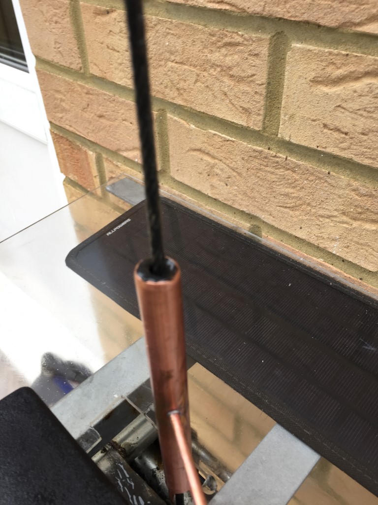 The finished product works quite well and gives an even coating to the wire rope, the length of the 4mm pipe was to allow the spray can to rest on a bracket, so I simply raise the mast and hold the spray button down 🙂