
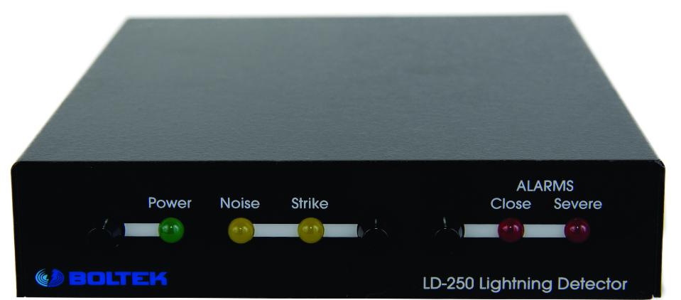
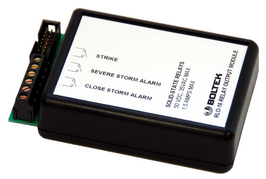
The LD-250 Lighting Detector from Boltek has an internal output for a relay interface, the manufactures units are quite expensive, so I decided to make my own.
Inside the LD-250 is a 14 way header which connects via ribbon cable to the RLO-10, off eBay I bought the 14 way ribbon cable and IDC cable mount socket for £5.00.
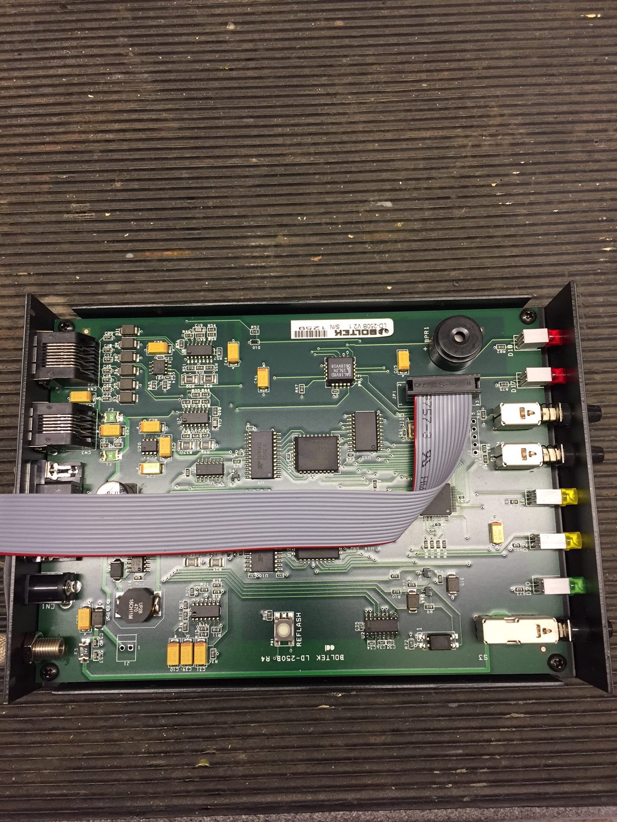
Opening the LD-250 the header JP1 is immediately obvious:
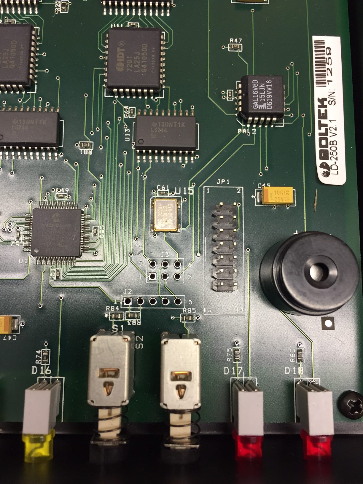
Using my multimeter, the header output pins linked to the front panel LED’s and the operating voltage was quickly found.
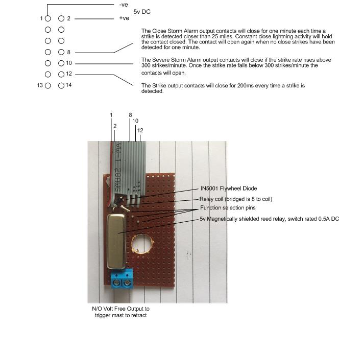
Using a spare strip of veroboard I mounted a magnetically shielded reed relay 5v, with flywheel diode across the coil, and the switched Normally Open reed output to a 2.54mm x 2 pitch connector, I also put veropins in the board so I can select which function I want the relay to operate on, should it be needed in the future.
The reed switch is used to switch 24v DC to an indicating LED and a a PLC input, the total load was measured at 21.49mA, well within the 500mA rating of the reed switch.
The module was placed in a small enclosure: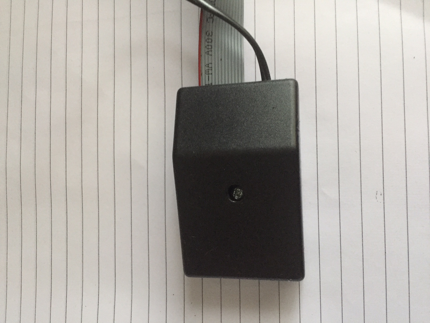
The ribbon cable was then plugged into JP1 inside the LD-250:
Switching on the Boltek performs a self test of the front LED’s and internal buzzer, as I have used the output from the ‘Close’ LED, the reed relay operated and the mast which was raised, automatically retracted.
All in all the project performs as expected and cost me £7 (enclosure was £2) saving me £58.95 on a factory unit.