Installing Boiler Condensate Runoff

Updated 14 November 2024

Overview

I currently have a Vaillant Thermocompact 624 System boiler which was installed in 2002 and some of the parts are now obsolete, so its only a matter of time before it needs replacement.

All new boilers now have to reach an ERP (Energy Related Product) minimum efficiency of 92.5% and only condensing boilers can achieve this, it does this by recovering the latent heat within the exhaust flue gases, this causes the water component of the flue gasses to condense and require disposal.

The boiler condensate produced varies in quantity and is acidic, therefore, only plastic parts can be used within the drain system (no copper or cast iron pipes unless the condensate has been neutralized first).

My existing boiler has no need for a condensate drain, however, when this packs in, any new boiler will.

I have read that if the condensate drains runs outside into a gully or soak-away, that the external pipe unless lagged or trace heated can freeze in the winter, and if the condensate can’t run away freely, the boiler will lockout until the pipe is thawed out.

Installation

So, that’s the backstory, fortunately for me, the boiler is in the garage and also a portion of a 11/2″ (40mm) drain pipe runs inside the garage, before going through the wall to connect into the soil stack, the drain pipe carries the waste water from the washing machine, dishwasher and utility sink.

darin pipe

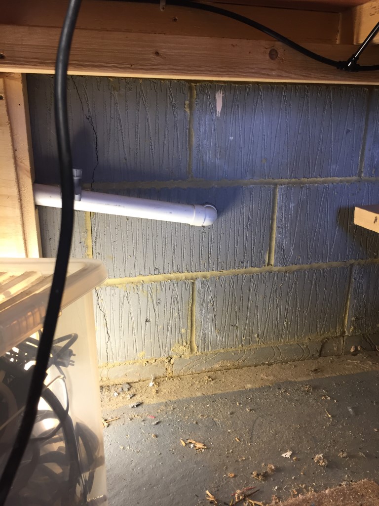
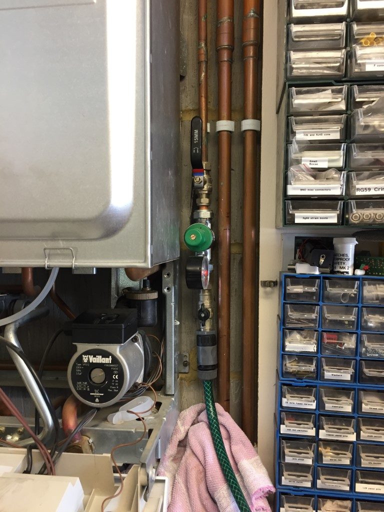
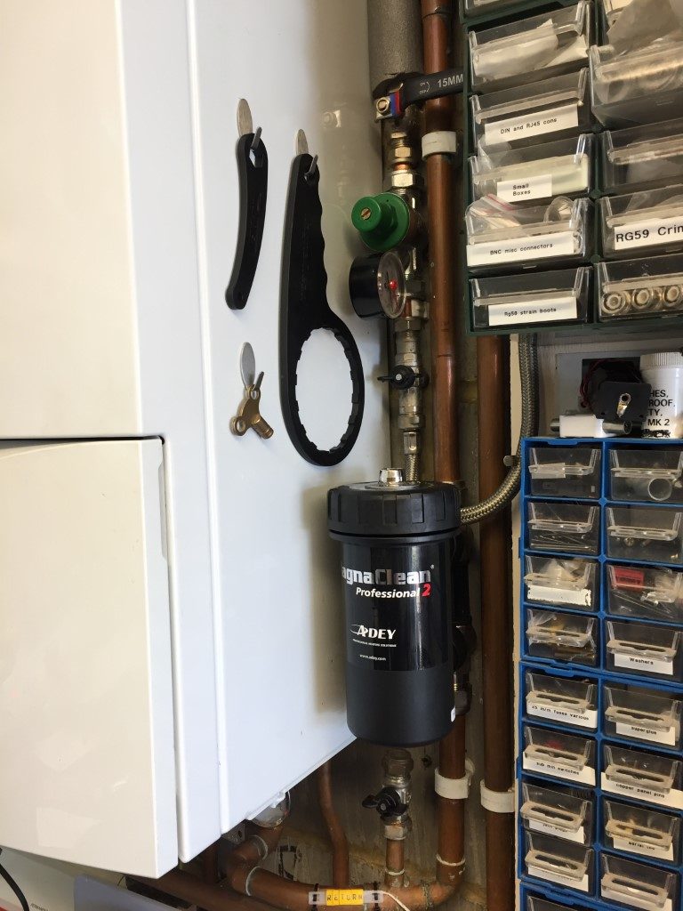
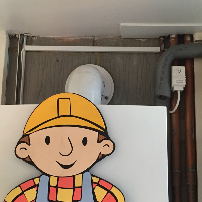
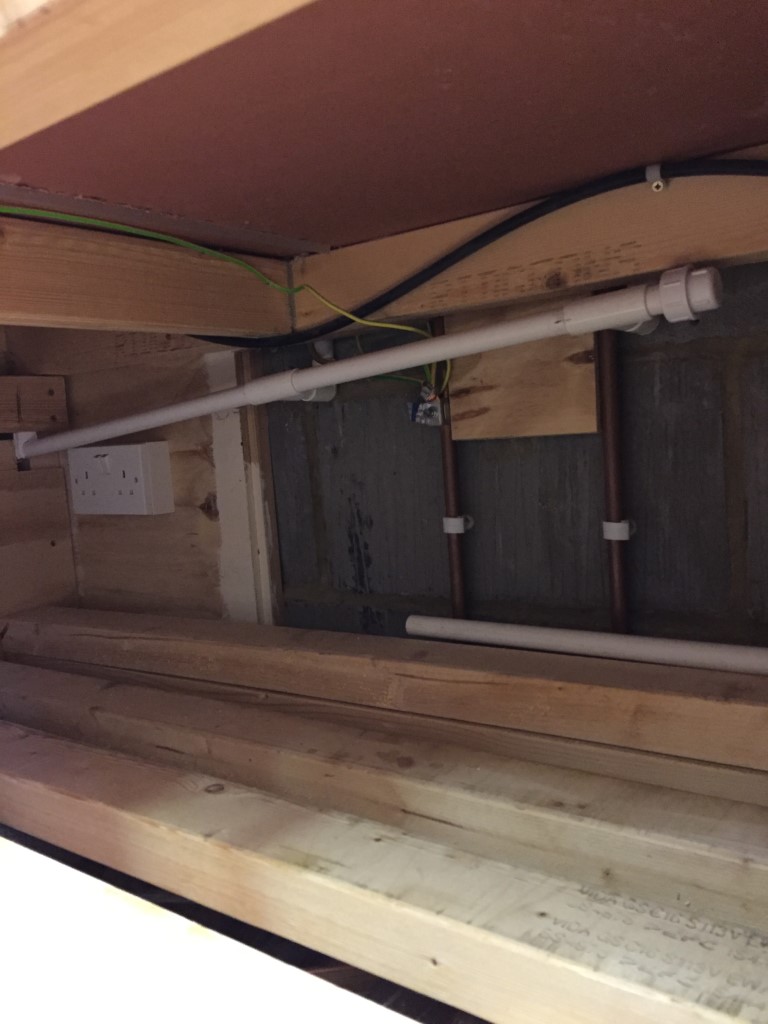
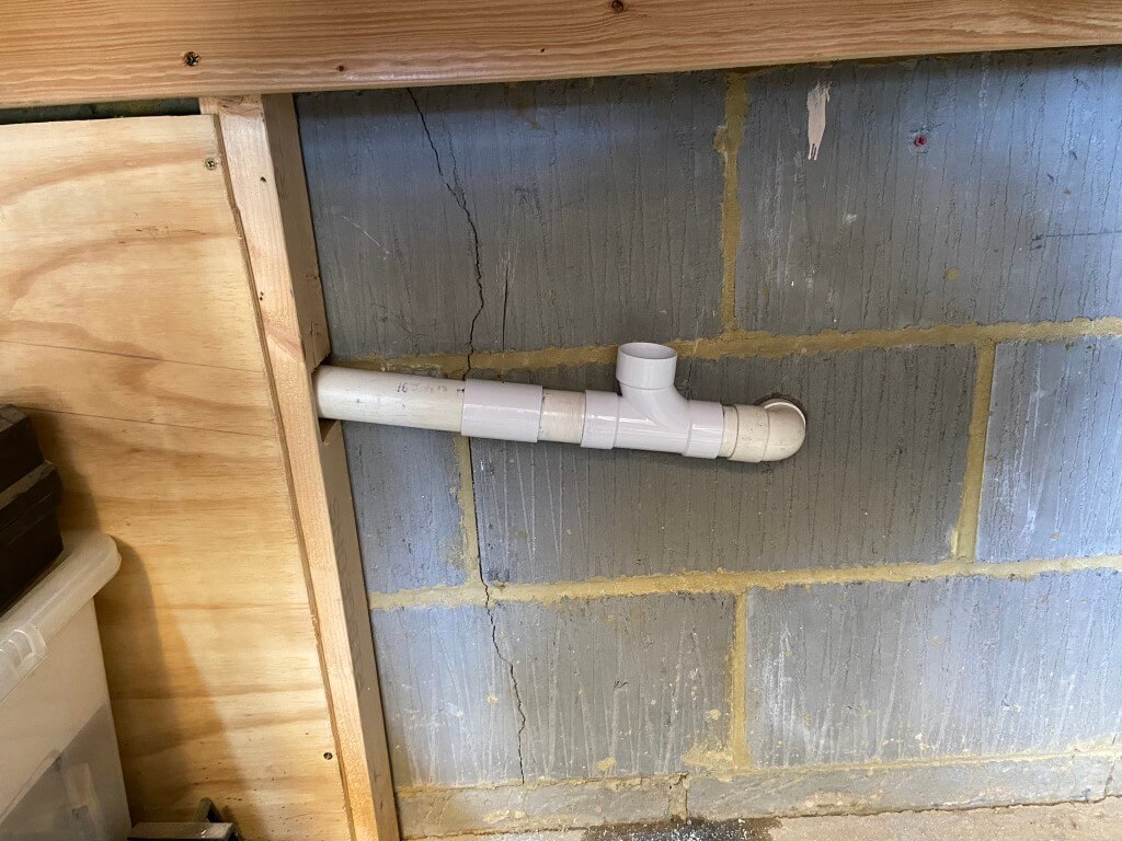
The pipe used was 22.5mm plastic overflow pipe from the boiler to the drain pipe clamp, the picture below shows the capped boiler condensate pipe in advance of the installation.

capped condensate

Fitting this pipe without taking the garage apart was a ‘challenge’ and took ages!

wide angle

This pipe runs behind dado trunking where I used plastic cement to fix a 90 degree bend and ‘Tee’ with a capped stub so I can flush through if needed.

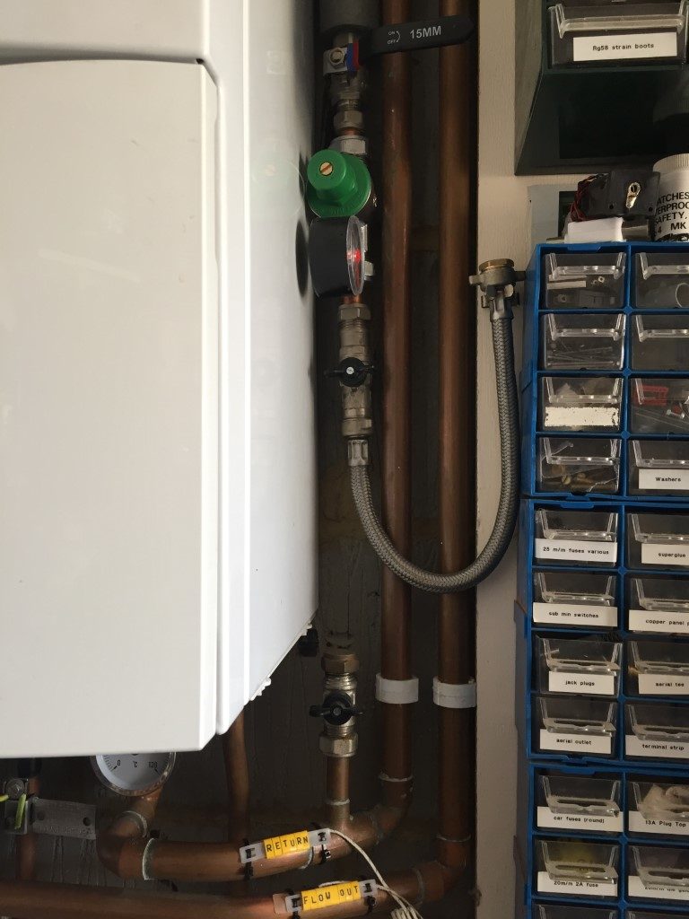
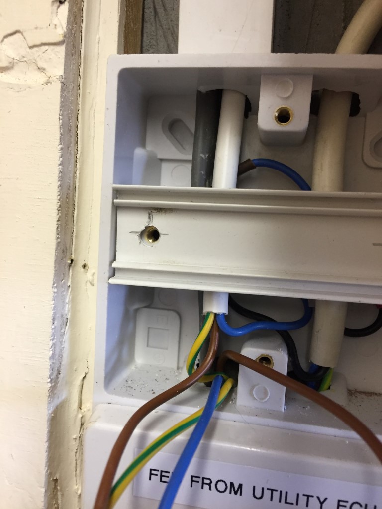
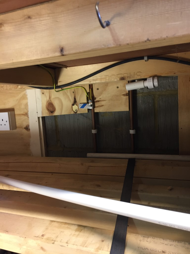
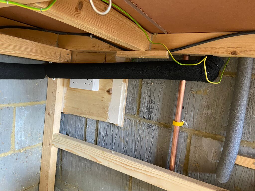
In this picture you can also see an earth clamp, this is fitted to the 15mm copper gas pipe  and is the main bonding conductor for the gas, unfortunatly it does not comply to BS7671 Electrical Regulations,  in so much as it is futher than 600mm from the point of entry and it is also installed after a branch, so I took the oppertunity to install a new clamp and 16mm2 main bonding conductor directly from the meters outgoing gas pipe to the consumer units earth bar, I could have used 10mm2 as I have a PME supply, but as I had the wire already, I made use of that.

tee

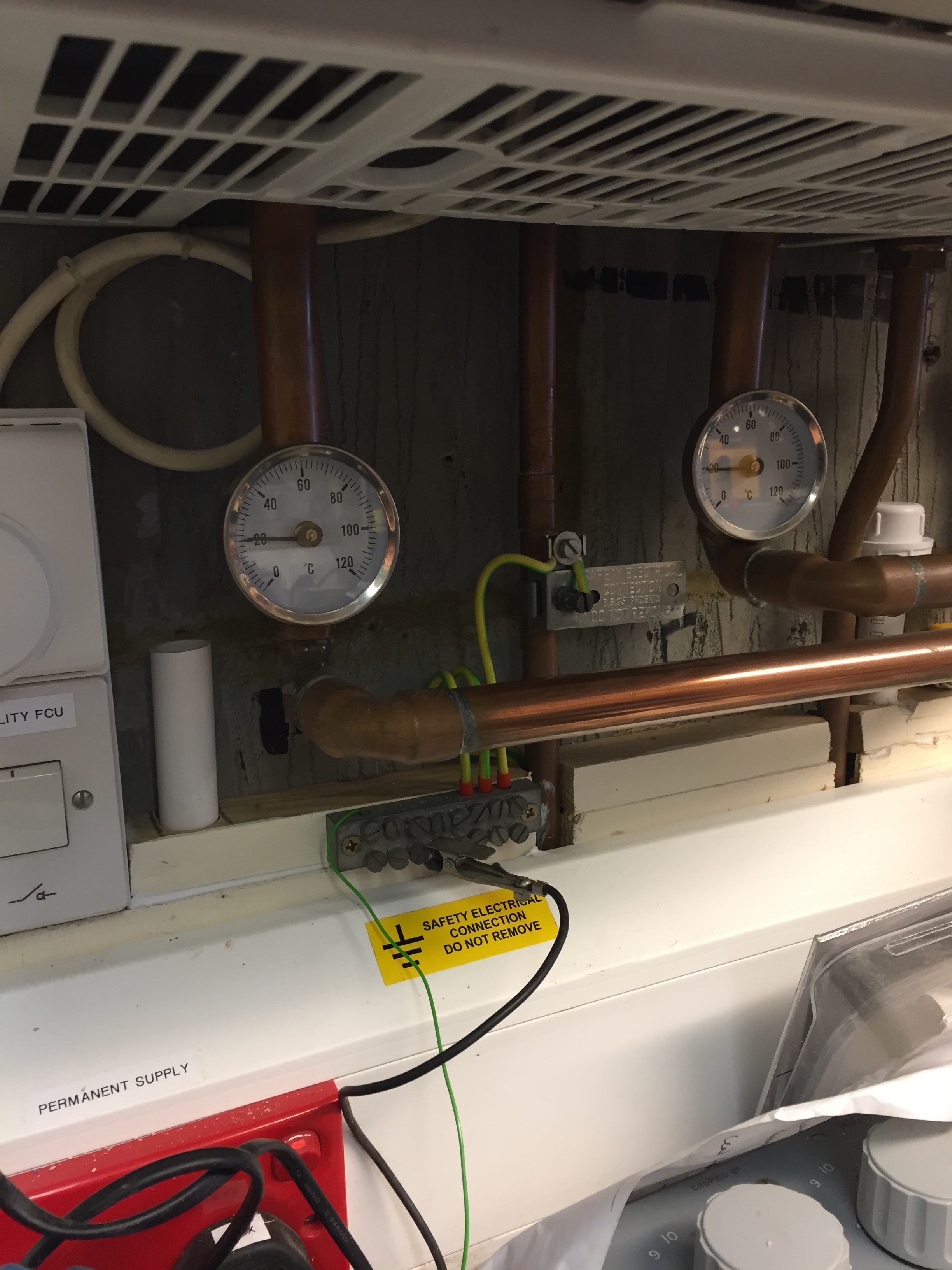
After doing the first drain I rechecked the pipe layout on a Vaillant EcoTech and it showed the condensate oulet on the other side of the boiler, so it was out with the drill again and fit another drain.

two pipe

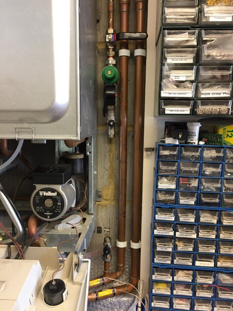
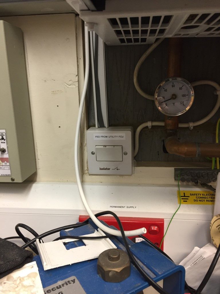
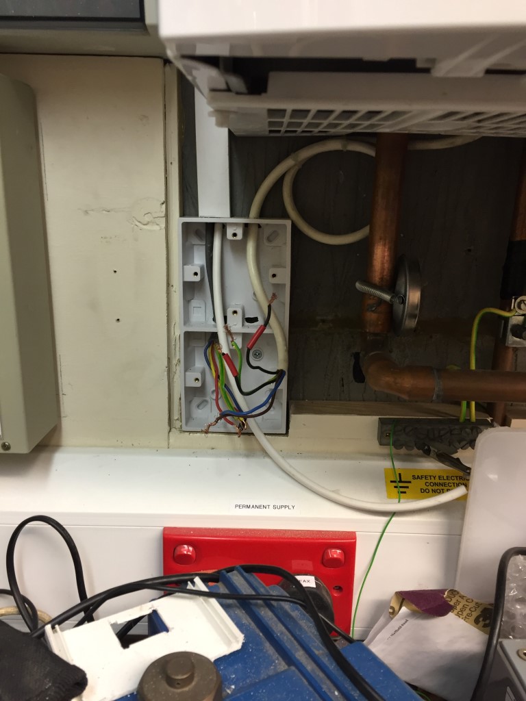
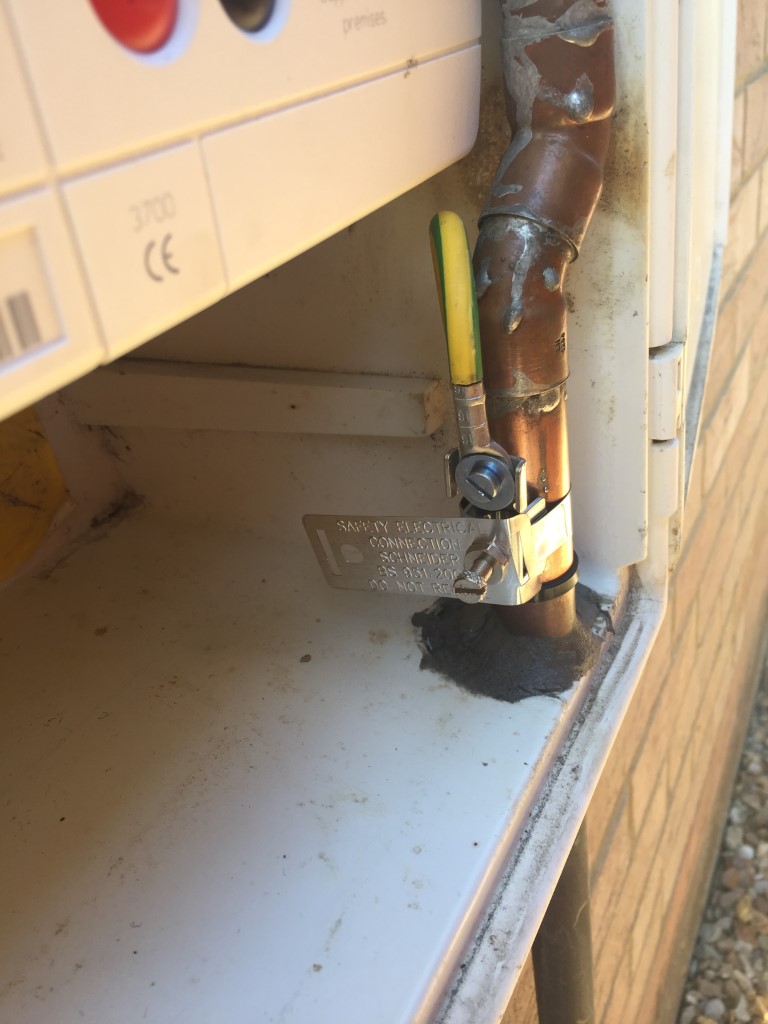
This is the new gas main bonding conductor clamp fitted with the cable sealed after being routed of the enclosure, note the quality pipe soldering done by the British Gas Smartmeter man……Nice!

bonding

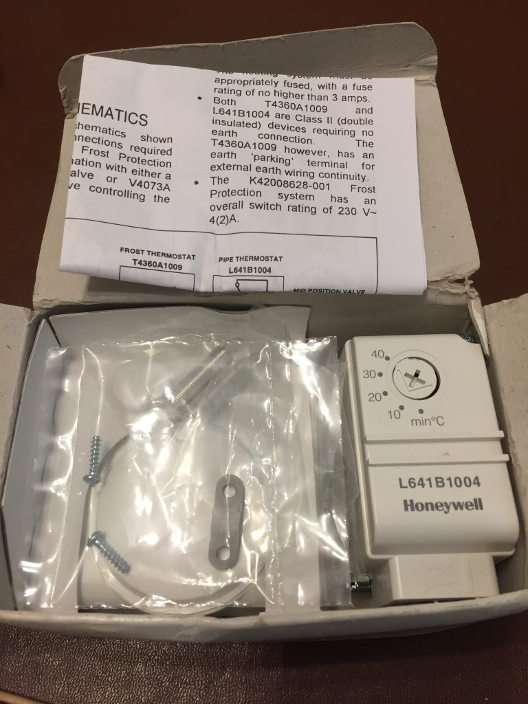
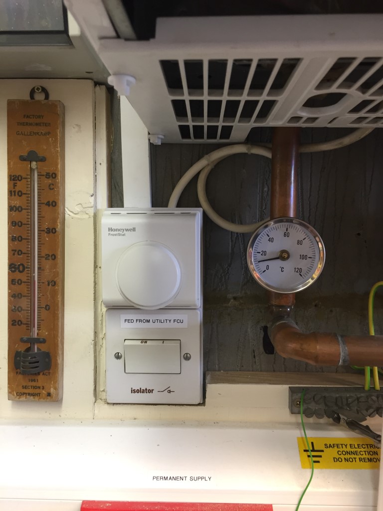
The additional uncapped drain below was a lot easier to fit as I removed the boilers isolator and frost stat to make more room.

left side

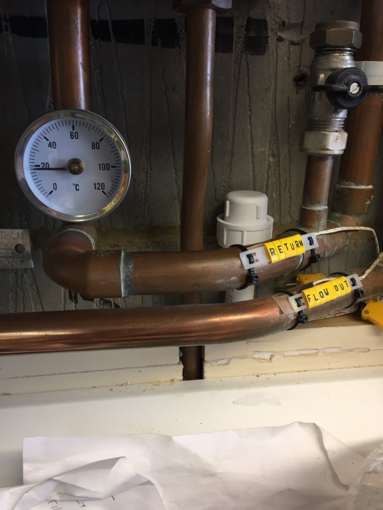
The drain has to have a fall of 43mm per meter, the pipe was taken to a 90 degree bend and then on to the drain pipe, the pipe is supported every 300mm.

trap

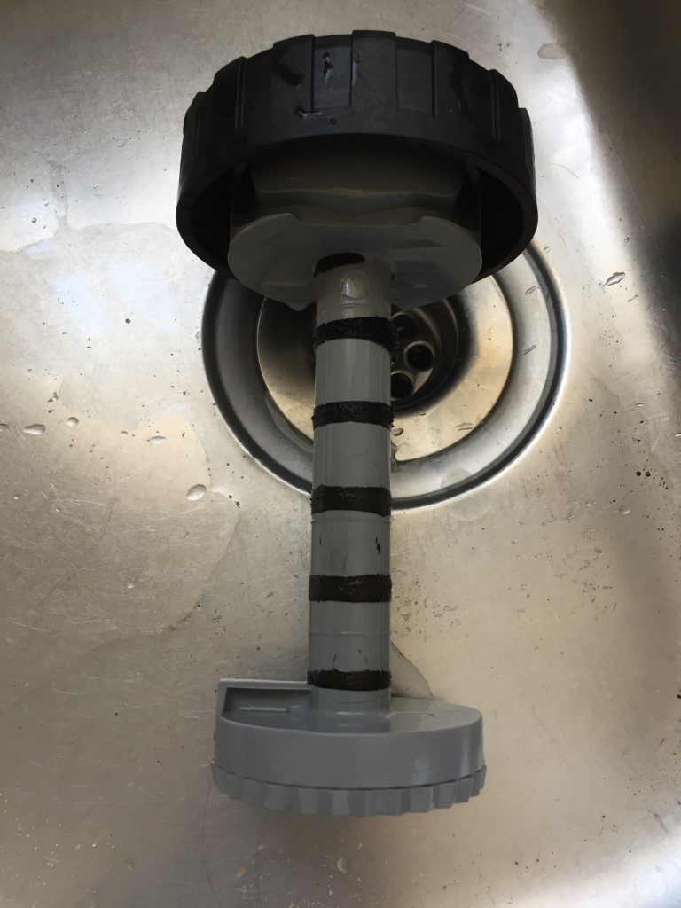
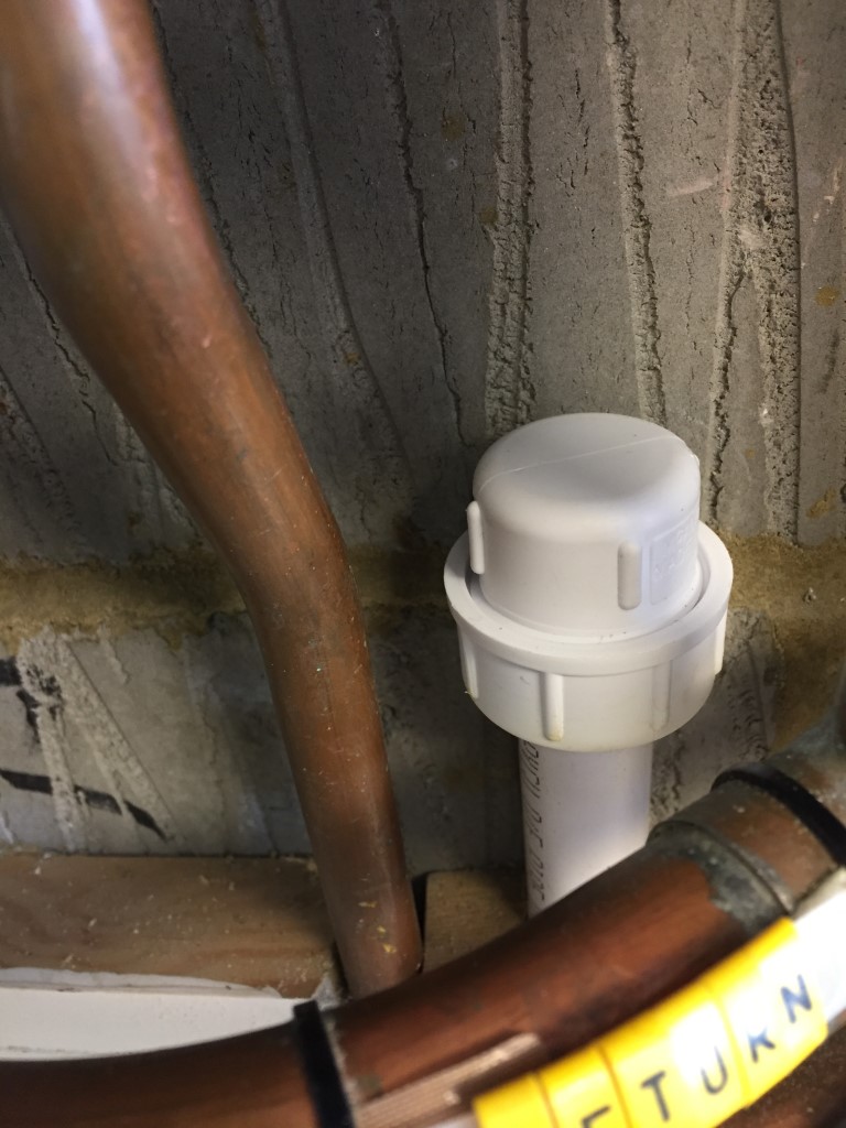
The  picture  shows a 75mm deep trap in the 22.5mm pipe, this then goes on to a McAlpine CONVALVE R28-NRV, this Non Return Valve will allow the flow from the boiler, but will restrict any back-flow from the drain pipe.

Installation of the NRV was very simple, I had to chisel the breeze block slightly so the clamp could fit without touching the wall, then drill a 15mm hole in the drain, debur the hole and fasten the 4 clamp screws and that’s it.

As the main drain pipe was at an angle and the condensate pipe came in vertically (the NRV will only work in this position), warming a small length of pipe and with an internal bending spring, I put a slight bend in the pipe, this was then cut to length and fitted between the pipe clamp and the NRV.

Once fully installed and all joints cemented, I ran a full bore water hose to check for leaks, once everything was checked, the exposed pipes were boxed in to stop any accidental damage (this pipe does form part of the boilers flue system when connected) and the garage was put back together again.

Not sure when my boiler will fail, but at least I’ve saved the plumber some time and effort and therefore I’ve saved some money in the long run.

Update

April 2023, Ideal Vouge Max 18kW system boiler ordered, checking on the guidance in Part L of the latest Building Regulations, there is now a requirement to insulate condensate pipes in unheated rooms, as my garage falls into this category, I have revised this blog.

Rip out and start again

12 April 23, Gas Safe engineer came to cap off the gas to enable me to remove and install a new boiler, he noted the existing condensate pipe size and as the boiler is located installed within an integral garage, this is classed as an unheated space and as such the condensate pipe will need upgrading to 32mm and protected against freezing by Class ‘0’ waterproof insulation.

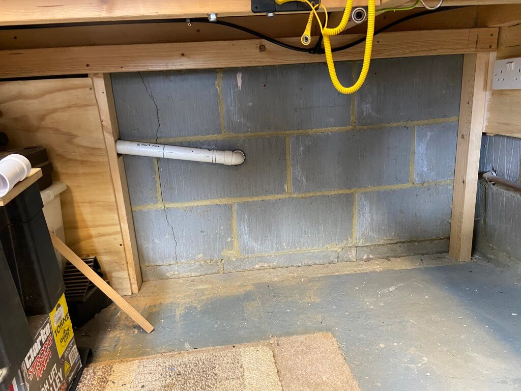
So, time to start from scratch.

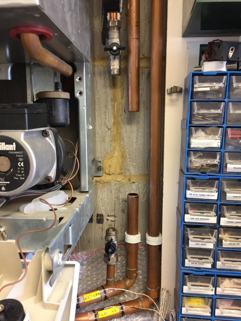
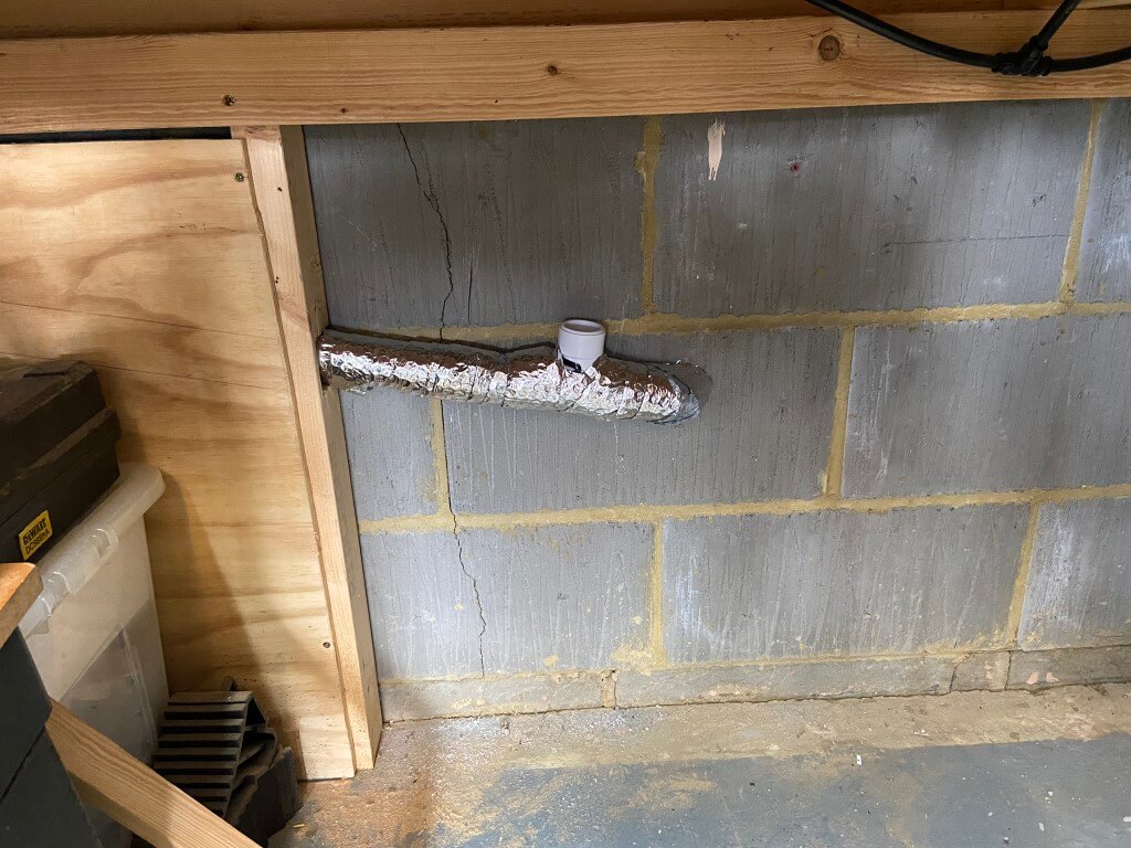
After removing the pipe lagging and McAlpine condensate pipe clamp, I was left with a new starting place.

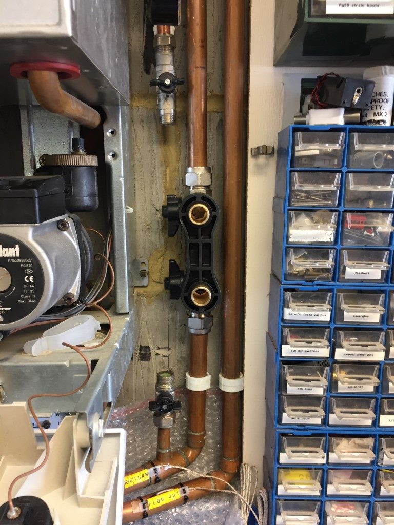
The pipe above is 40mm solvent weld waster pipe, so I decided to insert a 40mm Tee with a 40mm to 32mm reducer for the condensate.

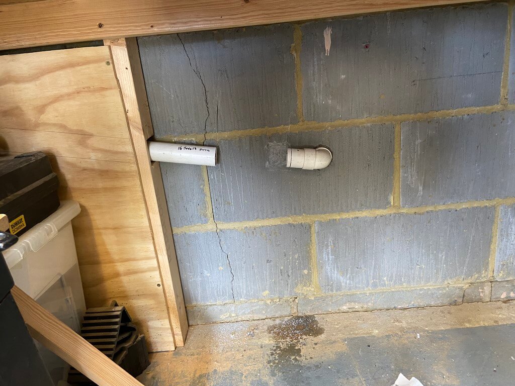
I had very little movement in the pipe as both ends were fixed, so I couldn’t simply cut the pipe and insert the Tee.

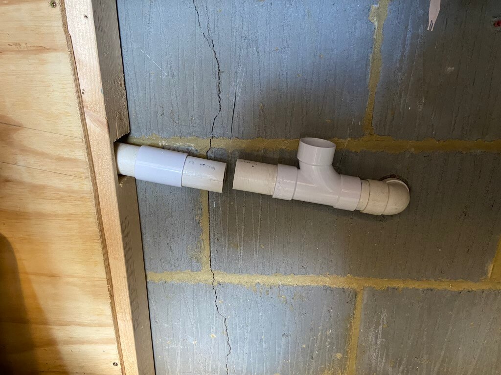
To get around the problem I filed the inner lip smooth of a 32mm coupling (socket), to make a slip coupling and cut the pipe, sliding the slip coupling onto the pipe, then fitting the Tee.

Solvent welding a stub of pipe in the Tee and then sliding the slip coupling back over the pipes to connect them after solvent welding.

All done ready for lagging.

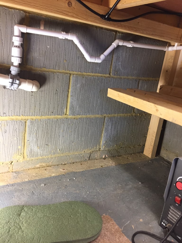
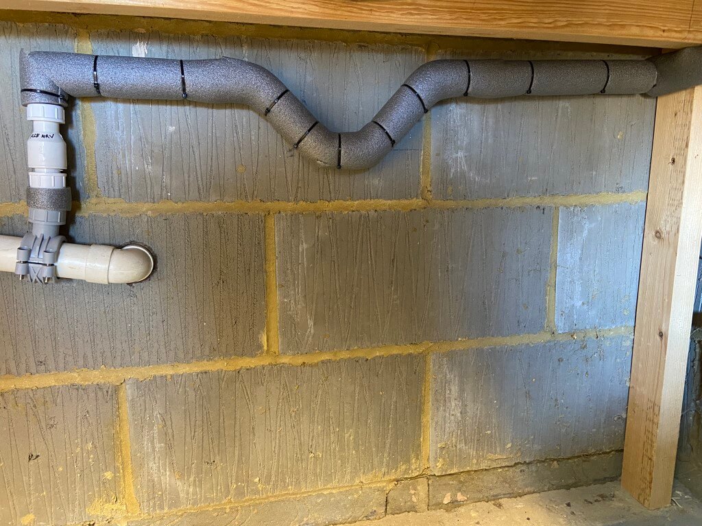
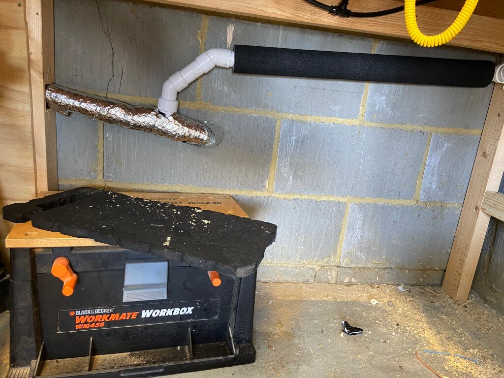
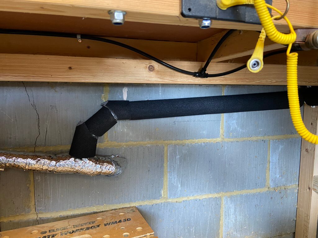
Lagged with 32mm reducer installed ready for the 135o degree bends to take the pipe to the boiler with the correct fall.

32mm pipe was then installed up to the boiler and insulated with Condensate Pro lagging .

Once all the pipe was lagged it was time for a coffee and give my knees a rest!

New boiler all installed and fully compliant.

MFJ 1786 Magnetic Loop Modification

mfj

I bought at used MFJ 1786X (240v version) from Tony G3RGQ (sadly now SK), I have been after a magnetic loop for quite a while, so when the opportunity presented itself to buy one at a reasonable price, I went for it.

The 1786 covers from 30m through to 10m, looking on Youtube was a modification to increase coverage into the 40m band.

After looking at the video it was off to eBay:

  • K15U-1 47pF 10kV 8kvar Capacitors including delivery from Ukraine £13.57.
  • Vacuum Relay 10kV 3A including delivery from Poland £23.53.

Opening the case and looking at the butterfly capacitor, I located a way to securely mount the capacitors and relay.

butterfly

I had some left over copper sheet, so I cut a 25mm wide strip 100mm long and used this as the capacitor linking strap and mounting brackets, making sure I had a solid connection to one side off the butterfly capacitor.

caps

The relay was mounted to the opposite side of the butterfly capacitor using a similar strap to that on the capacitors. To avoid straining the glass relay switch connection, I used some RG213 braid to link the capacitors connection to the relay, I deliberately didn’t secure the base of the relay to the fibreglass insulating sheet, this is to make the relay ‘floating’ in an attempt to reduce the chances of relay breakage.

relay

I installed a ‘flywheel’ diode across the relay coil (coil voltage  27VDC) to protect the operating switch in the shack.

Once the loop case was refitted, the modification was tested and works fine, many thanks to the Youtube author for sharing his practical experience.

Update 1 June 18

I bought a offset pole and 9 x 9 bracket to mount the magloop on, the existing 6 x 6 bracket was too undersized and slightly in the wrong position, the new bracket was fixed with M10 sheild anchor rawlbolts.

The tricky bit was getting it mounted due to it being top heavy compounded by a cranked pole, the solution was to use a pully arrangment from the mast to take the weight to help get me up the ladder and also position the pole to put the ‘U’ bolts in 🙂

loop up

LED Emergency Light Kit

em kit

I saw a very similar discrete emergency light fitting recently and thought that would be a good idea over the stairs at home, looking on eBay I saw the above unit (MJ-LED-DZ09 by Zenergy) for £14.95 and bought one.

Prior to use, the instructions recommend charging the battery for no less than 24 hours before use as it comes discharged, this I did.

The LED light housing is really neat, it requires a 32mm hole (1 1/4″) drilling to accept the light body which is held in the hole by spring clips on either side, the electronics are in a low profile enclosure and this will easily pass through the 32mm hole.

Installation was very simple, I marked the center of the ceiling over the stairs, using a 32mm hole saw, checking that their wasn’t any joists or obstructions in the loft  above the ceiling before drilling.

To stop plasterboard dust going everywhere whilst drilling the hole, I used a plastic fast food container as a ‘dust catcher’.

To make this, I cut a hole in the container so that the hole saw shaft passed through the container into the chuck, this allowed me to hold the container steady whilst drilling the hole at slow speed so that all the dust was trapped in the container.

After pushing the electronics enclosure through the hole, I used decorators caulk around the inside lip of the LED light, before pushing the light into the hole, the reason for the caulk was to form a decent seal to stop any draft marks appearing around the fitting at a later date.

off

In the loft, I connected the emergency light 230v power to the upstairs lighting circuit (after isolating the supply!), when the power was turned on, the battery was then plugged into the unit ready for testing.

With the power on, a tiny green healthy LED is lit, when the power is off, the green LED goes out straight away, and within 2 seconds, the main white escape LED lights, I assume the delay is to avoid and short duration blips bringing on the main LED.

The light from the unit is very bright and cool white is colour.

lit

Quick Details from Web Site
LED –   1 X 3W LED
Material-     Poly Carbonate for conversion body & aluminum LED body
Mounted –    ceiling mounted
Life time of battery –    4 years
Light Output –       (Emergency)    170lm
Lamp protection –   over charge and discharge protection
LED indicator –   Green indicator
Charging current  –  90mA
Convert voltage-    155V  AC
Discharging current –   500mA
Discharge duration –   3 Hours
Spec of battery-    3.6V  2200mAh NI-MH Batery
Packing –   38.5 x 35x 32.5cm     50pc/ctn
IP Rating-    IP20

NO.:MJ-LED-DZ09

Application:

The series use for emergency lighting. The unit will provide 3W maximum output power at emergency mode.They are designed to be highly efficient and highly reliable, and with short-circuit protection; overcharge protection;over discharge protection and over temperature protection.

Important information for the installion:

The unit uses dangerous mains voltage,(220-240Vac, the converter will be with the emergency mode when the mains voltage is less than 65% of rated voltage) it should be installed by a qualified electricians only according to European safety standard or relevant nation regulations.

Connect the LED spotlight to the emergency LED converter with correct polarity according to the schematic drawing.

Connect the unit to AC power only after the wiring completed between emergency converter, battery and spotlight.

If the emergency converter is used for purposes other than originally intended or it is connected in the wrong way, no liability can be taken over for possible damages.

 Specifications:

Model Main power supply Main power cut off
MJ-LED-DZ09 LED Spotlight off, green indicator on LED spotlight on, green indicator off

I’m really impressed with the product, and its another safety related home improvement which we hope is never needed in anger.

Update 6 June 18

Installed a Emergency light test switch rather than turning the lighting power off, these are just under £3.00 and include the ‘fish tail’ key.

Em Switch

The switched fused connection unit is for a cupboard light and Hive light fitting which are fed with 0.75mm cable, the emergency lighting is fed with 1.5mm cable and is not fed from the fused side of the fused connection unit.

PCB Etch Tank

I decided to build a PCB etch tank for some up and coming projects, so this is a quick blog on how I did it.

etch tank

For ease I bought four pieces of 5mm thick clear Acrylic (Perspex), each piece pre cut to A4 size (210mm x 297mm) off eBay for £5.41 per sheet, the height of 297mm is also ideal to accommodate the immersed heater.

You only actually need three sheets, from this two full sheets are each side with the third sheet requiring cutting to form the sides of the tank, whats left over is the base, the idea is minimal cuts and make best use of factory cut edges to cement forming a leak tight joint.

I used a tenon saw to cut a 40mm strip the length of the sheet (40mm x 297mm), once cut, I turned the sheet round and marked 40mm in from the remaining factory cut edge, and cut the second wall strip.

The piece left over, I used as the base of the tank after shaping it using a jig-saw with an Acrylic cutting blade, I found that better results for straight cuts were with the tenon saw, rather than the jig-saw even though I used a straight edge.

Once the base was shaped I flame polished the edge.

With all the pieces  cut, the edges were rubbed with 1200 grip paper and cleaned with IPA, before being cemented.

The cement used was Model X Pro plastic weld, 50ml costing £6.69 from eBay, this came with an syringe applicator which was invaluable for accurate use.

I used butt joints ensuring factory cut edges only are cemented to the flat surface of the sheets, once the parts are checked for alignment, the plastic weld which is like water, is applied and ‘wicks’ along the joint giving a really strong joint, reaching full strength in 24 hours.

I did make a couple of brackets for the heater and a lid for the tank out of the remaining Acrylic sheet, but this was not absolutely necessary.

sideUsing the dimensions above, you should end up with a tank which is 45mm deep, 215mm wide and 297mm high, to cover the heating elements ‘water line’ will take 1.3 litres of etchant and will cope with 1.5 litres.

From a local aquatics shop I bought 6mm air line, air pump and bubble wall to agitate the solution, the heater is a 300W 230v EPH-20 Kinsten Etchant version from eBay and was quite expensive at £16.53,  this has adjustable higher temperature settings than normal fish tank heaters (33°C to 55°C), the tank is set for 40°C.

ready

Exposed photo resist board ready for immersion in Ferric Chloride to remove the unprotected copper.

Central Heating Inhibitor Testing

I recenly refilled my central heating system after completely draining down to install an automatic bypass valve and then a partial drain down to install a Magnaclean filter a bit later on, when the system was refilled I used Fernox F1 inhibitor (£18.99 per 500ml), as I didn’t know the volume of water in the system to meet the required minimum of 5% inhibitor per 100 litres of system water, and to be on the safe side, I used two bottles of Fernox, as you can not overdose the system, but this is wasteful and not to mention expensive.

In order to use the correct amount of inhibitor, I needed to find the volume of water and ‘spend to save’, so I bought a couple of inhibitor test kits, a Fernox Protector Test Kit for £23.46 and Sentinel x100 quick test for £4.99.

kits

So, why did I buy two test kits!

When the system was completely refilled I used Fernox F1, a few months later I decided to install the Magnaclean and needed some pipe fittings and inhibitor to top up the system resulting from the partial drain down, however, the merchant didn’t sell Fernox F1 only Sentinel x100, so I bought that.

Reading on a plumbing forum their was a suggestion that it was not a good idea to mix different manufactures inhibitor in the same system, I read this after I had already bought the x100 quick test kit off eBay.

I was refunded the cost of the x100 which was good of Plumb-It in Huntingdon, and bought Fernox F1 from another merchant and I also decided to buy as a long term investment a Fernox test kit.

As I now had two test kits, I thought I would see if the Sentinel x100 quick test would give an accurate indication of inhibitor strength of Fernox F1 as the x100 quick test kit will do two concentration tests for £4.99, rather than spend over £23, having said that, I can do 25 tests with the Fernox test kit, so it is cheaper overall, but as a DIY’r getting the x100 kit is more cost effective.

x100

Reading the hazard data sheets for x100 and Fernox, they contained the same chemicals and concentrations, Fernox F1 had one further component:

  • (Fernox & Sentinel) <2.5% Benzotriazole
  • (Fernox & Sentinel) 5% Sodium Molydate
  • (Fernox) Nitrilotriethanol

So I decided to test if the X100 kit would work in practice.

test1

Running some system water off using the vent on the Magnaclean, you fill the container to 1cm from the top and add two tablets, shake and then wait 10 minutes, the colour of the solution should then be compared with back of the x100 packet, if its the same yellow colour or deeper, its fine.

test2

Using the x100 test, the result appears my system water is of an adequate concentration.

The Fernox Inhibitor Test Kit was slightly more involved than the x100 test, but not difficult, the first thing to do was establish as baseline for your cold water which was used to fill the heating system with water.

f1

Filling the supplied container with 10ml of tap water, you add drops of the reagent and count the number of drops needed to change the solution from Blue to Orange.

blue
This is after one drop.
4 drops

To change my tap water from Blue to Orange took four (4) drops of reagent, shaking the bottle after each drop, this number will be subtracted from the drops total in the next part.

Washing out the container, I refilled this with central heating system water to 10ml as before.

f2
1 drop

One drop of reagent added.

9
Nine drops of reagent added.
nearly

Very nearly there.

39

After 39 drops, the solution changed to Orange, subtracting the baseline tap water 4 drops, means that 35 drops were needed overall, referring to the kit instruction, for Protector F1 at the recommended dose of 500ml for 100L of system water, a minimum of 9 drops of reagent is required to change from Blue to Orange, obviously, I’m well overdosed!!

This got me thinking of how I can determine how much water is in the heating system, the Fernox web site suggests that in a domestic system, volume can be estimated by counting the number of single panel radiators in a property and multiplying by ten. remembering to count double panel radiators as two single panels.

I have 13 radiators with 3 of these being doubles, therefore, using the formula above, this would be 16 x 10 = 160 Litres of System Water needing  just over 1.5 x 500ml bottles of Fernox F1.

To cross check this approximate value, I went the manufactures site for my radiators and found the data sheets, checking the sizes of my radiators against the Kw output of each one, this equaled a total of 10.87Kw, allowing that 1Kw requires 11 liters of water and adding a overhead of 25 litres for water in the boiler, indirect heating coil and system pipework, it worked out to 144.5 Litres of System Water needing just under 1.5 x 500ml bottles of Fernox F1.

The next time the system is completely drained I’ll use one 500ml bottle and then test to confirm if indeed it does need more than one bottle, once established I’ll sell the test kit on eBay.

Magnaclean Pro 2 Installation

Updated 19 April 2023

Note – Boiler replaced, however Magnaclean has been retained, Blog HERE.

MAGNA

Today (21 April 18), I decided to install a Magnaclean Pro 2 in my heating system which has a system boiler with hot water and central heating controlled using the ‘S’ plan design.

Magnaclean removes suspended solids (ferrous (Magnatite) and non ferrous) from the circulating water and traps them within the canister, this is then cleaned out at regular intervals.

The removal of these particulates will improve the longevity of the boiler and its parts, although my system water has been previously treated with inhibitor and ran clear during the drain down to fit this, these devices are installed when boilers are replaced in compliance with Building Regulations Part L , so I thought I’d bring it up to code.

The instructions specify that the Magnaclean is installed on the return to the boiler after the last radiator and before any system filling/pressurisation point, next to the boiler was a good location for me.

before

In order to make room for the Magnaclean to fit, the cold water filling loop needed to be raised.

drain

With the boiler power isolated, the case was removed to give more working room, a hoselok fitting was screwed onto the cold fill line and a hose ran to drain, I then isolated at the stopcock and drain the line ready for cutting the 15mm copper pipe and raising the whole assembly.

lifted

Cold fill raised and leak tested, the maximum height was governed by the length of the braided filling loop, the 22mm copper pipe nearest the boiler is the return and this has two marks 150mm apart indicating where the cuts need to be made.

I used the hoselok fitting on the return filling valve, and drained the heating system water opening a couple of upstairs radiators to break any vacuum.

pipe slice

Using a 22mm pipe slice it was fairly easy to cut the pipe, due to the restricted working space, I had to use pump pliers to grip and turn the pipe slice through some of its travel.

magnaclean base

The Magnaclean has a slip socket allowing the unit to slide over the pipe, then once engaged, the unit is lifted slightly so the inlet pipe engages allowing a nut and olive compression fitting to be made, I used jointing compound on both top and bottom olives before tightening.

The isolation valves are on the left, rather than the right, I had to use this orientation so I could easily access the isolation valves, I was going to use obtuse street elbows to form  a tight set in the return pipe, lifting the  Magnaclean clear of the flow pipe so I could operate the isolation valves, but this was way too much work for no real gain, especially as effective fluid flow is a function of the Magnaclean canister and not the valve orientation.

finished

Once the canister was pushed into place and the lid was tight, I closed the radiator vents and started to fill the system watching for leaks, the filling system pressure reducing valve is set for 1.5bar, so this was left open as I went round venting the upstairs radiators.

With the first round of venting done, I vented the Magnaclean and boilers circulation pump before turning the boiler on to heat.

This was followed by more venting until the majority of the air subsided, I isolated the Magnaclean and drained it so I could add 500ml of Fernox F1 inhibitor to the system, using the canister as a dosing pot.

As I only partially drained the system, (downstairs radiators are below the boiler so I only drained upstairs), 500ml should be sufficient to top up protection.

The installation went well with no leaks, and once the Magnaclean was proved to be ok, I registered the device online for the 10 year warranty.

I’ll post pictures in a few weeks of the Magnaclean magnet to see what it has picked up.

5 May 18 – Checked the Magnaclean and this is what it had caught:

magnatite

My Vaillant Thermocompact system was installed in 2003 and has 13 radiators piped in 10mm.  I’m very happy with the low level of magnetite retained and nothing was trapped within the lower filter housing, I’ll check this again in a years time, but so far so good 🙂

Central Heating Frost Protection

Updated 8 February 2023

Due to the recent cold snap and the fact that my central heating boiler is in the garage, I thought I’d install frost protection which will override the heating controls and fire up the boiler when the frost stat air temperature is  at or below +5℃, on the return pipework to the boiler is pipe stat set for +25℃ to turn the boiler off.

I have a Hive system which has a frost setting on the internal thermostat, this will bring the heating on if the temperature falls to +7℃ or below, the garage frost protection supplements this.

I spotted the Honeywell Frost Protection Kit – K42008628-001 comprising of a Frost Stat and Pipe Stat for £27.00 on eBay which is a really good price compared to Screwfix, Plumbase and Toolstation, so I bought it.

stat

For the installation, apart from the stats, I needed some heat resisting cable for the pipe stat and a double mounting box.

2 core and earth (3093Y) 0.75mm2 heat resisting white round flexible cable was bought off the internet from Under Control Instruments (www.undercontrol.co.uk)  for £4.00 which is temperature rated to 85℃.

The double gang surface box took a little bit of searching as I needed one with the flexibility to be used either vertically or horizontally with face-plates in the correct orientation, this cost £3.99 off eBay.

switch
Original installation showing the boilers isolating switch, the white flex is from the pipe stat.

First job was to wire the pipe stat and install it on the return pipe to the boiler, the stat is held in place with a spring which hook onto lugs on the base of the stat, getting the spring behind the pipe and stretching it to fit was made easier by tying a piece of string to one end of the spring and passing that behind the pipe.

Hooking the spring on the stat lug and keeping tension on the string, offer the stat to the pipe and pull the string to stretch the spring round the back of the pipe and hook it on the opposite lug, once done the string is simply cut off, this worked very easily once you got the knack.

pipe stat

With the power isolated, the existing isolator was opened and a picture taken for reference.

The Blue (Neutral (N)), Yellow (system calling for heat – switched 230v (L2)) and Red (Live (L1)) are from the junction box wiring centre, the opposing wires in the isolator are to the boiler.

isolator

Once everything was identified and proved dead, the wiring was removed and the new double gang surface box was fitted and wires pulled back in.

The two red sleeved blacks were separated, one will be connected back into L2, the other will be used by the frost protection system.

dual

The isolator was wired up and screwed into place, then the frost stat was fitted but it did not sit right as it was very slightly smaller than the back box so I needed packing to make it level, for this I used an off-cut of trunking lid, which did the trick.

packing

Once the Froststat was fixed in place and connected, the power was turned on and the frost protection tested by simulation that everything worked ok, including the operation of the Automatic Bypass Valve, once done the trigger temperature was set and the stat lid fixed in place.

I did notice a draft from behind my changeover switch on the left of the picture which was blowing across the face of the froststat, so I sealed the gap with decorators caulk to avoid inaccurate operation of the stat.

frost stat
Froststat and isolator, I bought additional lower cover screws and two were missing, the part number is Vaillant 290811 Clips.

As I have recently installed an Automatic Bypass Valve, I have not connected the frost stat to any motorised zone valves, therefore, once the air temperature is at or below +5℃,  a switched live will be applied to the boilers ‘calling for heat’ via the red sleeved black wire, the boiler will now fire and the circulation pump will operate.

As the motorised valves to either the central heating or hot water cylinder will be closed (‘S’ Plan system), the pumped water pressure will ‘lift’ the automatic bypass valve, maintaining a heated water flow to the boiler via the return pipework to which the pipe stat is affixed.

Once the return pipework is above +25℃, the pipe stat opens the series wired connection from the frost stat, this removes the switched live to the boiler, and the boiler enters ‘no heat run on mode’ before switching off.

The job took 2 hours and cost £35.00 and although we have never had a problem, the boiler and pipework in the garage should have had effective frost protection from day one.

Update

19 March 18 – The boiler came on unexpectedly and it was caused by the frost stat, closer inspection reveled that one of the bimetallic switch support pillar was snapped inside the unit, I’ve contacted the seller on eBay to see if I can get a replacement.

20 March 18 – eBay seller responded to my mail and is sending a replacement unit out.

24 March 18 – Replacement froststat arrived in good order and installed, all working now and the original unit sent back to the seller.

15 December 2022 – Had a few really cold days of around -5oC and the garage internal temperature sensor was reading 4.25oC

I took the cover off the frost stat and I must have moved the dial when I was replacing the lid as it was set below +5oC, I have readjusted this now, so all should be good.

3 February 2023 – Timeguard TRT031N electronic frost thermostat arrived from Fastlec at a cost of £22.36.

Manual for Timeguard

I found the mechanical frost stat to be quite inaccurate, the replacement is electronic and should therefore be reliable.

BRK 86RAC Smoke Detector Replacement and Additions (UK)

Updated 6 January 2022

I have two BRK 86RAC Ionisation type smoke detector, one in the Hall and the other on the upstairs Landing, these were installed by the builder and in 2008 I added a heat detector (690MBX) in the garage, all three devices are mains powered with battery backup and are interlinked so that they all alert to a detection.

BRK 86RAC
BRK 86RAC Discontinued ionisation smoke detector.

Checking the batteries in the smoke detector I noticed the unit has a life of 10 years from date of manufacture which was 21 June 2002, as the date of noticing this was 4 March 2018, they are well overdue for replacement!

The BRK 86RAC is no longer produced and has been replaced by the  BRK 670MBX.

brk

Checking my local Screwfix had BRK ionisation smoke dectors (part number 81969) for £12.99 and the surface mounting kit (part number 30152) for £2.99, I thought I would add two more to my system, so bought  four of everything.

On opening the boxes, I didn’t realise that the detectors came with 9v PP3 type batteries, so wasted £6.00 buying them, and the other thing was that they are not a direct replacement, the 86RAC base is a smaller size and the plugin connector is a different style.

parts
In the box are the above plus instructions, sticker for the consumer unit and protective detector cover, no fixing screws are supplied.
Fitting –

First job was to isolate the mains supply to the existing detectors which are on their own dedicated circuit, once this was done I twisted the detectors from the base to allow me to take photographs of the wiring.

The existing wiring was Black to Neutral, Brown to Live and Orange striped is the interconnect wire, 670MBX uses Blue for Neutral, Brown to Live and Grey for the interlink, the existing detector had a ferrite bobbin through which all the detector wires passed, whereas the new model doesn’t, I decided to reuse these on the replacement units.

old

Once the cable colours were recorded, the detector was unpluged and the base completely disconnected to allow the replacement of the new base, once this was screwed into place, the connections were remade.

base

The wiring in the base looks more complicated than it should due to the change of cable colours, the existing 1mm CSA 3 core and earth used the pre EU harmonisation wire colour convention of Red, Yellow and Blue,  the cable to the new additional detectors which I have installed are in the office and IT cupboard, uses harmonised colours of  Brown, Black and Grey, as the installation has mixed wire colouring, a warning notice to this effect is fixed to the consumer unit.

While the new detector was on the desk, the battery was dated and connected, without a battery installed the detector will not engage in the base, this is a safety feature.

After making the connections, the detector base was fixed to the surface fitting by two supplied screws, the cardboard sealing gasket was then pressed into place covering the detector base fixing holes, the next step was to plug the lead into the base of the detector and lastly twist the detector into the base.

new

Within the baseplate of the detector is a small plastic extrusion  which can be removed, this is used once the detector is installed as a locking clip preventing the detector being removed from the base with the clip in place.

With all detectors connected and new ones installed, mains power was turned back on, and each detector was then checked that it showed a continuous green LED for power healthy and a flashing red LED every 60 seconds to show the detector is functioning.

The center test button on each detector was pressed and held, this caused the local unit to sound, followed a moment later by all the other interconnected heads.

I had already sealed the cables passing through the ceiling, the final job was to seal the base to the ceiling and paint the exposed part of the ceiling as a result of the base being smaller than the original one.

A point to note was that I was going to use flushed in circular dry lining boxes to make the connections in and hold the base, this would have made the smoke detector sit closer to the ceiling but would of meant a large hole being made, so I decided against it.

Job was very straightforward, adding new detectors was easy as I looped off the landing detector to the other units which were only a few meters away.

ESi Electronic Hot Water Cylinder Thermostat – ESCTDE/B – Part 1

UPDATED -27 April 2022

Background

In order to save energy and better regulate the temperature of my domestic hot water in my Santon Premier Plus unvented cylinder, I decided to install a ESCTDE/B Electronic Dual Cylinder Thermostat manufactured by ESI Controls, I bought online from PlumbNation.

box

Installation

The ESCTDE/B has two thermisters, one for the temperature reading and control, the other is for over-temperature trip and is set for 80℃, I must have a big problem if this operates as my boiler output temperature is set to 68℃.

thermistor

Fortunately the Santon Premier Plus has a spare dry thermostat pocket which the thermistors are a perfect fit.

pocket

I marked the location of the thermister pocket on the outside of the cylinder cover and offered up the ESCTDE/B back-plate and marked the centre hole.  I’m not sure what the ESCTDE/B is specifically designed to fit, but the rear fixing was perplexing and I didn’t want to modify the casing of the unit in case I invalidated the warranty.

back
Rear fixing arrangment

I used a cut down 20mm Female Adapter as a center bush, this was cut to size and fixed to the front cylinder cover.

bush
20mm Female Adapter
bush
Cut down female adapter used as a through cover fixing method.
bush
Fixing bush installed.
bush
Inside cover showing bush and thermostat pocket.

ESCTDE/B fixed to the bush with the three back-plate screws and as the female adapter has a serrated edge, it holds very well, the existing cylinder thermostat was turned up to position 5 which is 72℃, I have left this in circuit as another backup to over-temperature, as mentioned earlier, my boiler output temperature is set to 68℃, so only under a fault condition should this protection operate.

fixed
Indirect temperature setting and top view of fixing to ESCTDE/B.
Cover
Thermistors sliding into cylinder pocket.

Connections

NOTE – The mains supply to the ESCTBE/B MUST be from the same source as the heating systems programmer, this will ensure that there is only one point of electrical isolation for safe working.

I used 1mm 4 core and earth from the ESCTDE/B to the heating connection box, the ESCTDE/B does not have an earth connection, so this wire was parked, the unit requires a permanent 230v feed, the temperature calling relay changeover contacts are NOT volt free, although they are simply wired in series with the existing cylinder thermostat.

If the Legionella setting is active on the ESCTDE/B, the unit will automatically switch 230v to the Domestic Hot Water motorised valve (NOTE- this overrides any programmer settings), which in turn will bring on the heating, the output from the ESCTDE/B will remain on for 1 hour when the tank temperature is above 61℃.

As the bending radius of the connecting wires within the unit is quite tight, I used ferrules on the end of the wires, this ensures that no ‘whiskers’ can cause problems later.

wire
Ready for wire stripping.
wires
Insulation removed and conductors twisted.
wire
Bootlace ferrule pushed on.
wires
Bootlace crimped and job done.

Conclusion

Finished installation all working, as my hot water system is directly fed, (no header tank), I did not need to enable the ‘disinfection mode’, this mode increases the water temperature to 61℃ for 1 hour to kill Legionella, however, as the feature exists, I set it to activate once per week.

finished
We had been away for a few days hence the water temperature was showing 21℃, the unit was initially set for 48℃ and the Red LED shows the cylinder is calling for heat.
finished
Picture showing wiring from ESCTDE/B to heating terminal box and the tank temperature now reached the set-point of 48℃.

Problem

Apologies for not updating this blog and a recent comment made me revisit this, so thank you.

I have decide to make a Part 2 to the ESi showing how I addressed the problem of the the heating coming on outside of the scheduled time due to the ‘legionella’ setting being on.

Part 2 is HERE.

A blog about stuff that interests me or I have done.

Social media & sharing icons powered by UltimatelySocial