Central Heating Enhancement

I was reading on the plumbing forums about the need for an Automatic Bypass Valve (ABV) on central heating systems and compliance with the HM Government  document – Domestic Building Services Compliance Guide, specifically the need for a ABV (page 15, section 2.0).

I have a System configuration using a Valliant Thermocompact 624e boiler, the purpose of the ABV is to maintain a consistent flow through the boiler and also should both the hot water and central heating zone valves close due reaching the set point temperature, the boiler will continue to run for 10 minutes to dissipate heat in the the boilers heat exchanger, without some form of bypass the pump will be pumping against closed valves, which is not good!

The ABV senses the increase in pump pressure and opens against a calibrated spring pressure to maintain water flow.

S Plan

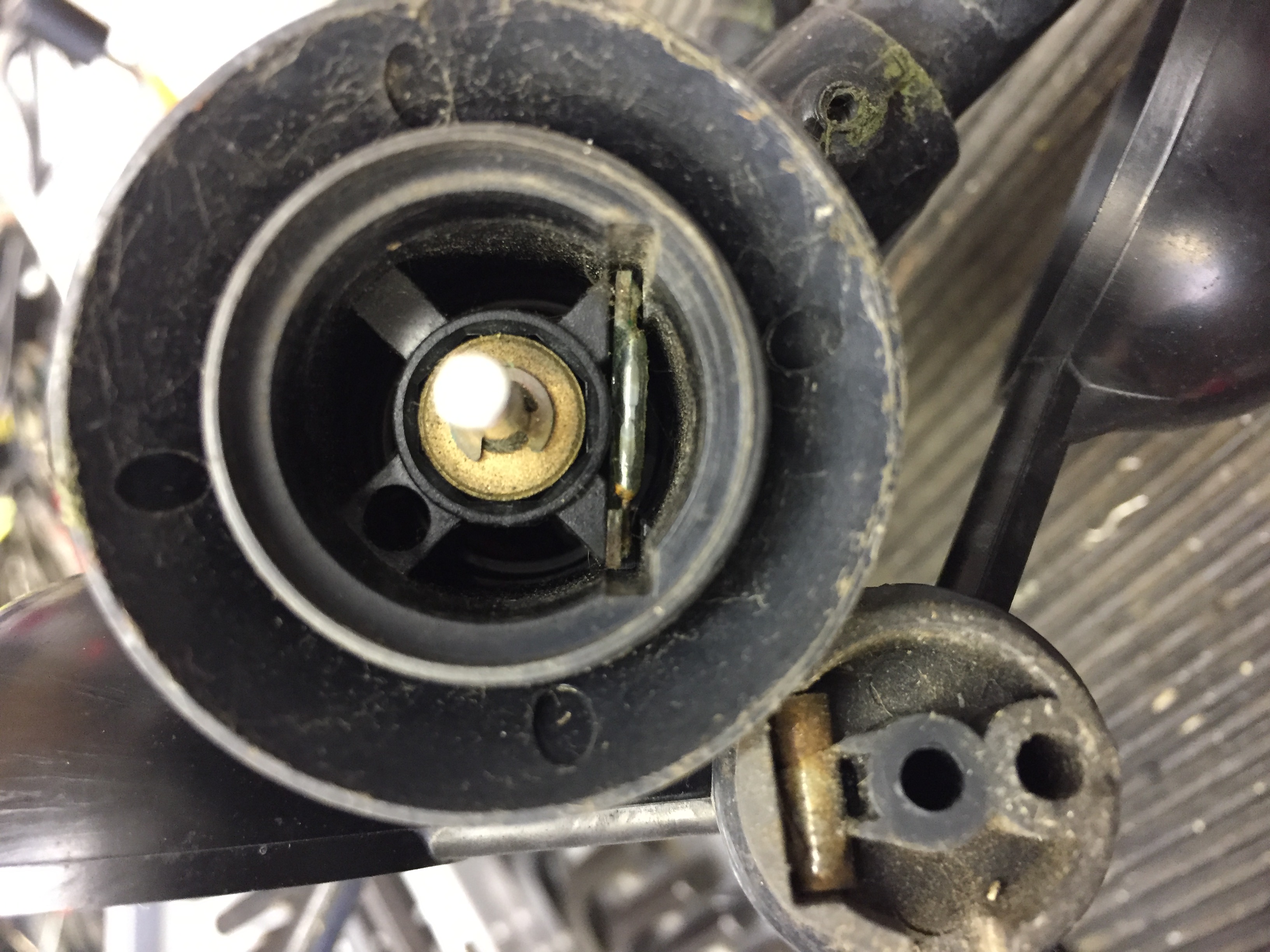
My central heating system had a 15mm hand valve cracked open between the boilers flow and return for this purpose, the 28mm pipe with an automatic air vent is the feed from the boiler, the centre 22mm pipe is the return.

start

The advantage of this configuration is that the pump can not pump against a dead head, the disadvantage is that a portion of the heated water from the boiler is immediately returned to the boiler and not used the heat radiators or hot water, so I thought I’d install an Automatic Bypass Valve not realising that the boiler already had an inbuilt one until I had bought all the parts…oh well!!

The manual bypass valve was not the only thing I wasn’t entirely happy with, the main niggles were the motorised valve to the heating circuit was mounted very low and it would be better to move it higher for ease of replacement and the automatic air vent was not at the recommended height above the highest point in the system, both of these were going to be fixed at the same time as the installation of the ABV.

First job was to electrically isolate all power to the boiler and controller, once done it was a matter of draining the system down, I’m fortunate that my radiators have drain valves, this made the process very simple.

Once drained I could disassemble the pipework.

strip

I retained the hand valve for adding inhibitor and for use as a vacuum break should I need to drain down in the future.

Once the pipework was apart, I used a 22m straight compression coupling to extend the central heating pipe, lifting the motorised valve  to a more accessible location, the pipe to the automatic air vent was also extended to be 300mm above the height of the upstairs radiators.

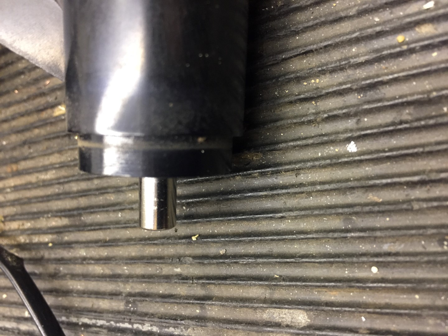
The tricky job was to unsolder a 22mm stub which was cut to allow the pipework to come apart.

solder

With the heat mats in place, I was surprised how easy it was to desolder the stub from the feed pipe elbow, once the stub was out, I could start to  dry fit the pipework so that the ABV exit pipe was directly inline with the return from the hot water cylinders heating coil.

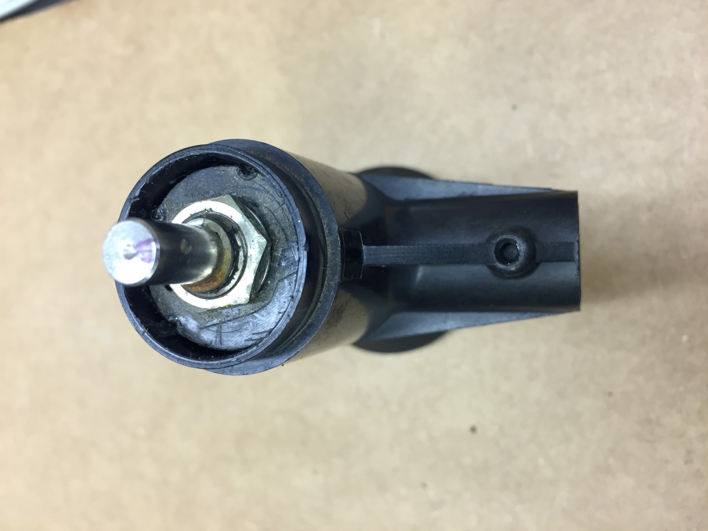
Once everything was aligned, I removed the head of the ABV so as not to melt anything inside it when I started soldering the fittings.

finished

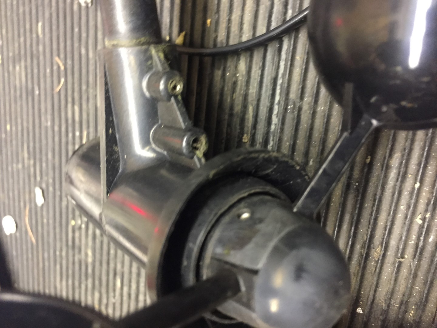
This is the finished job, I used another compression fitting on the return pipework to make any future ABV replacement easier as the whole assembly can be broken down, something you cant do with soldered fittings.

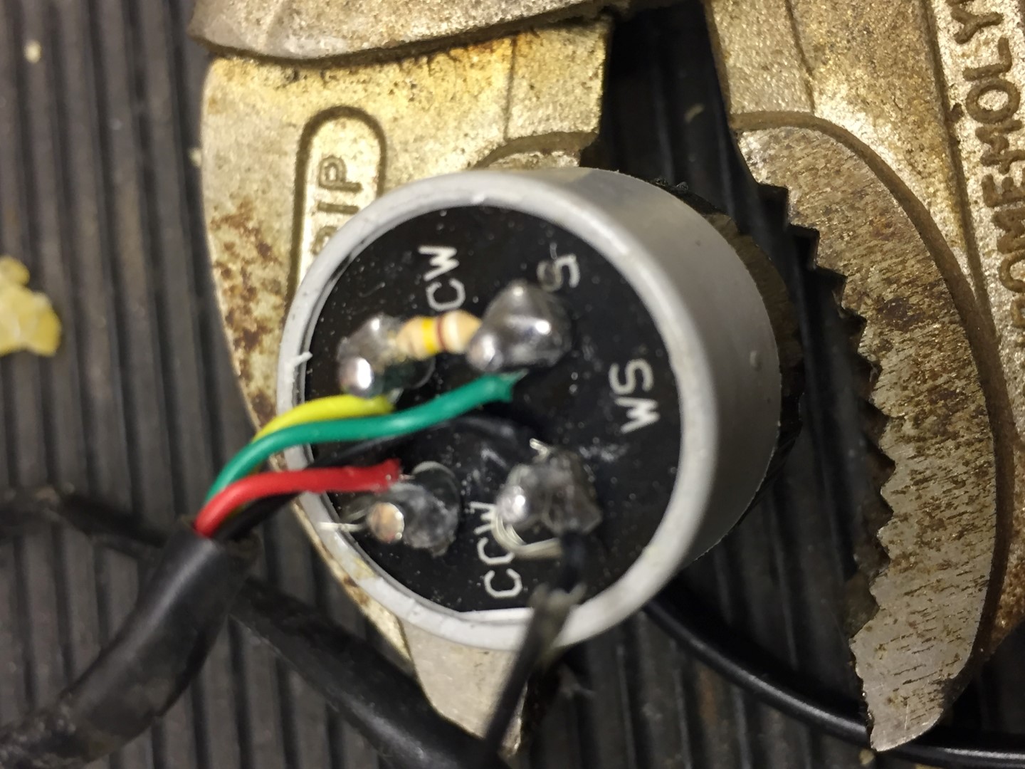
British Gas replace one of the motorised valve heads and they don’t open the Honeywell junction box to connect the new head wiring, they add an external junction box which looked naff, so I remade the head cable off as it should be done.

The system now needed to be refilled, I coupled a length of 15mm copper pipe with a tundish to the original hand valve and added 1 litre of Fernox Protector F1, once done the pipe was removed, valve closed and a screw cap was fitted.

Mine is a closed system with no head tank, a filling loop from the cold water feed is used to add water and pressurise the system, as I knew there would be a lot of radiator venting, I installed a water pressure reducing valve inline with the double check and isolating valve already installed, this allowed me to set the filling pressure at 1.2bar and leave the valve open, rather than continually repressurising the system after venting air, this worked really well and saved loads of time.

loop

The picture was taken after all the air in the system was vented and the boiler pressure was 1.4bar and steady with no leaks, the loop was disconnected and capped off until next required.

To keep a beady eye on the the pressure over the nest few days I used a home CCTV system 🙂

pressure

The main problems I had was not having all the correct fittings to hand when you have to adapt from the original plan, I started the job on a Saturday morning just in case, and fortunately Screwfix is not too far away and they had everything in stock, including a new 22mm pipe slice as mine had packed it.

One thing which bothers me is that the builder used copper pipe where it can be seen and plastic where it can’t, this means that as your cutting pipe, it starts to turn inside the transitional coupling!!

I hate with a passion plastic fittings and have little confidence in them, fingers crossed they will last the test of time.

Sonoff POW – Power Measuring WiFi Switch

Sonoff POW is a WiFi switch with the added facility of monitoring power consumption to the load it switches also it can run trends over time and give instantaneous readings.

I currently use a Belkin power meter inline with my home network UPS so the Sonoff POW is a great addition enabling remote monitoring.

The first job was to attache the IEC plug and socket to the Sonoff POW, I had a small IEC extension cord which I simply cut in half and used that.

cord

Stripping the cable back, I used bootlace ferrules on the wires going under the spring connection terminals for a neat job.

connections

Once the connections were made, the lid was fitted which has integral cable grips to keep the cable from being pulled out.

lid

Making sure that the socket is used for the Input and the plug for the Output, I powered the unit up and paired it with my iPhone and the internet.

phone

To connect to the UPS, I simply unpluged the IEC plug suppling the UPS and placed the Sonoff POW inbetween, using the plug from the Sonoff POW output to reconnect to the UPS and thats it!

in line monitoring

The reading from the Sonoff POW and the Belkin seem to tally up, so well pleased, regarding the On/Off switching function, I will be using this test the operation of the UPS by simulating mains failure, the Sonoff App software allows for a detailed schedule to be created, so may well automate this as some point.

Sonoff Basic Voltage Free Relay Changeover Modification

What is Sonoff –

Home automation is “The Internet of Things”. It simply means the way all devices or appliances are networked together to provide customers with a seamless control over their home equipment.

Sonoff is an affordable device that provides users with smart home control. It is a WiFi based wireless switch that can connect to a wide range of appliances. Sonoff transmits data to a cloud platform through the WiFi router, which enables users to remotely control all the connected appliances, via the mobile application eWeLink. The cloud server of Sonoff is Amazon AWS global server.

Sonoff makes all home appliances smart. As long as the mobile has network, users can remotely control the appliances from anywhere at any time. Another feature available is to set timing schedules for the appliances, which can include countdown, scheduled on/off, and can thus, help users maintain an easy life.

ios
wifi
sonoff

The unit I needed to modify was the Sonoff Basic, this is a simple WiFi enabled unit which will switch 230v on or off, however, the application I needed was for it to switch a set of voltage free contacts, as these cost less that £6.00 each, its worth a go with the soldering iron.

The unit is very compact and before starting, I paired it with my mobile phone and checked that it worked correctly.

Sonoff open

The top simply clips off the base and the PCB comes apart without any fixings after cutting the paper security seal.

top
bottom

The relay has the Sonoff sticker on it and the mains is switched through the relay, the board uses double sided tracks for this.

Removed

The relay was desoldered and removed from the PCB, this then allowed access to the tracks which were cut with a Dremel.

bottom cut

The picture shows the bottom of the PCB with the tracks cut from the 230v input and a shorting link to complete the relay switching circuit.

top cut

This shows the relay back in place and the top tracks cut, the modification now allows a voltage free changeover which will be used to bring on my low voltage triggered external lighting.

Lighting Sonoff

Sonoff installed and connected to controller.

Sonoff Power Switching & Hive Light in Workshop

Sonoff Power Switching & Hive Light in Workshop

I’ve wanted to do a few tweaks to the home workshop for a while, and today I finally got round to it.

The easiest job was done first, this was to install an additional light fixture to house a Hive Smart Light, this has been added to the global Group ‘Lights’ in the Hive App, by the simple Alexa command ‘Lights On’ or Lights Off, all Hive lights and sockets with connected lights operate, this is really handy feature should we hear any noises in the night.

The light can also be turned on independatly via the Hive  App or via interfaces to other Apps’ or IFTTT.

hive light

I bought a cheap and cheerful circular light fitting for the Hive light as it’s very easy to wipe clean.  In the application I was using the hive light for, the lamp required an unswitched mains supply.

The besa box Tee above the Exocutor had the ‘loop in, loop out’ wiring for the suspended light, the new fixture was simply fed from permanent live from this and was up and running within 5 minutes.

The second job is something that I have wanted to for ages but the cost of the technology was prohibitive, until now!

workshop

The picture above shows my conversion of a garage into a workshop, this was done in 2007, after the walls were lined, the dado trunking and socket outlets were installed, you can make out that I have used Red and White sockets, the Red ones are not switched via a contactor, whereas the white ones are.

white red

Operating any of the three ‘Emergency Off’ latching buttons, will disconnect the sockets and non Red fused connection units.  A Red LED indicator by the bench  illuminates when the Power to the sockets is ON.

stop

The existing arrangement works fine , but I have always wanted an easy remote ‘power off’ ability, as I have had to check on countless occasions if I have left a soldering iron ON, my usual ‘gotcha’ is the compressor ‘kicking in’, in the middle of the night.

With the cost of internet enabled and Alexa compatable WiFi Smart switches coming down to a ridiculous price of £4.39, now was the time to make the addition of remote operation.

iso

To the left of the change-over switch is the consumer unit feeding the Garage sockets via a 20A MCB, a 3A MCB is for the contactors control circuit via the latching stop buttons.

The idea was to install a Sonoff Basic WiFi Smart Switch to switch the supply to the contactors control circuit.

wires

Cables fished in, Left side is the supply to the Sonoff, the Right side is the Sonoff’s switched output.

box

Sonoff connected and cables dressed in to consumer unit.

finished

Completed job with Sonoff showing link to server established, before starting the work I configured the Sonoff in the house and enabled the power to be ON by default, once this was done I checked that it work in the Garage.

The configuration is very easy and the App is EWelink, also this is linked to Alexa, the image below is a screen shot of the EWelink App.

app

The blog on the Rig switching is HERE.

Update – 5 Jan 18, E-WeLink servers have failed this means that control of the Sonoff devices is not possible, no time given as to restoration of service 🙁

14 Jan 18 – Service back up and running and all Sonoff devices now working.

Sonoff 4Ch Pro WiFi/Internet Switch Linked to Alexa

Sonoff 4 Channel Pro

sonoff

I have had an Amazon Dot for a while and use the interactive plugs and lights all the time, one of the plugs is for my Ham Radio PSU, so I have been looking for a relay interface which will work with the Amazon Dot, one of the key requirements is that the relays must be able to pulse on then off.

The Sonoff 4Ch Pro costs ~£25 and has 4 programmable relays including the ability to ‘inch’ a relay (pulse on then off), the reason this is important for me,  is that it allows a momentary trigger to the PLC controlling my automated mast.

The Sonoff 4Ch Pro is well made and can be powered from either the mains or 5 – 24v DC, relays are all voltage free.

The Sonoff App is EWeLink and allows direct control of the relays from anywhere, this App is then linked to the Amazon Alex App to allow voice control of the relays,m if you want to use voice control from your smartphone, Reverb is good.

EWeLink App needs an account setting up, once this is done, follow the instructions to pair with your router.  The default pairing LED flashing sequence did not work for me, I had to keep my finger on a relay button until the blue LED rapidly flashed and then followed the instructions.

Once paired, the blue LED remains steady, after a power down, WiFi locks within 20 seconds.

Sonoff Enclosure

I decided to mount the Sonoff 4Ch Pro in a 220 x 150 x 96mm ABS enclosure (£9.70 eBay), in Visio I drew the cutting stencil and transferred this to the enclosure.

The width of the Sonoff needing trimming slightly to make a snug fit, the get the correct height I packed the unit with 25 x 25mm wood off-cut.

enclosure

Using a Dremel equivalent, the lid was cut to accept the Sonoff.

enclosure

The IEC plug and socket stencil was attached to the side of the enclosure, using a scalpel, the cutting pattern was transferred.

cut

cut

Wired Sonoff 4Ch Pro, Relays 1 & 2 momentarily switch +24v as a trigger input to either Raise or Lower my mast, Relays 3 & 4 latch to supply individual IEC outlets.

The Relays and outlets are rated at 10A, the feeding plugtop has the appropriate fuse fitted.

wired

Finished unit tucked behind a PSU, LEDs show that Relay 3 is energized and WiFi is connected.

finished

The label below is the remind instructions on the voice commands (prefixed with ‘Alexa’) and how to change the relay names.

operating instructions

Update –

Had a huge headache trying to get this unit to re-pair once I had done some modifications to my home network and access point, looking through the help forums a large number of others are having the same problem, the solution which worked for was to put the iPhone in ‘Airplane Mode’ and follow the process to pair an Android phone (Touch) and not AP which had worked previously. What didn’t help was an unannounced outage of the European Sonoff servers!

The second issue which came to light was relay 4 would randomly operate, the fix was very simple, press and hold the internal S5 button to erase any pre-enabled RF switches.

Davis 6410 Anemometer Reed & Bearing Replacement (2000 – 2013 version)

Link to WXForum excellent article on Anemometer and Vane – HERE

Davis 6410 Anemometer

25 October 17 my wind speed sensor failed after 9 years service, the symptom being that the wind speed is always at zero after checking the connection to the ISS is tight and the cable to the anemometer is not damaged.

This is the blog is how to replace the reed switch and test its operation, also while it was in bits, I thought I’d take the opportunity and replace the bearings as well.

model

Information Sources

Online sources of information relating to replacing the Davies 6410 reed switch –

Parts Used

Magnetic Reed Switch 10mm MKA-10110 100v 0.5A Russia £3.50 for 10 from eBay.

Metal Shielded Bearing 0.125 x 0.375 x 0.156 Part R2zz £0.85 each from rcbearings.co.uk

Tools Required
  • Pliers
  • Sharp knife
  • Marker pen
  • Phillips screwdriver
  • 1.25mm or 0.05″ allen key
  • Soldering Iron & Solder
  • Magnifing Glass
  • Terminal Screwdriver
  • Glue gun (or similar adhesive)
  • Multimeter or battery & lamp.
Step 1

Remove the vane and wind speed cups to avoid damage.

Undo allen screw, if tight, use penetrating oil first, the screw does not need to come out.

Once the allen screw is loose, the vane is an interference fit, and with a little gentle force, pulls up revealing the potentiometers (pot) shaft.

vane

The shaft is not ‘keyed’ but will have a mark where the allen screw tightened against, when you reassemble, use this to align the vane so the screw tightens in the same place.

direction shaft

I marked the shaft showing the allen screw mark, I also marked the body of the pot in relation to the housing so that when I reassemble everything is in the same position and the wind direction reading will not be out.

pot

Step 2

Using the same allen key, undo the securing screw on the wind cups, once loose, the assembly slides off the shaft with little force.

wind

Put the wind cups and vane in a safe place till later.

Removing the wind cups reveals the reed switch which can only be accessed by removing the pot.

reed

Step 3

Breaking down the arm and releasing the cable, this is important when we come to remove the pot.

Undo the machine screw and slide this out, once the cable has been released from the in-built grips of the mounting bracket, the tube should slide out of the housing.

arm

The cable inside the tube has a crude cable grip made from an off-cut of plastic hose, either use pliers or a wood screw in the center of the hose, and gently tease it out.

hose

The next part is to slacken the two allen screws which hold the wind and direction body to the arm, once done, slide the arm down the cable to give you working room.

arm

Step 4

Removing the pot, this is a push fit and held in place by hot melted indents, these need to be cut away with a sharp knife.

pot

cut

Once the indents have been cut away, the pot will pull out of the housing, NOTEthis is a tight fit, use pliers to hold onto the pot shaft and draw towards you, Warning – I pulled too hard and pulled wires off  the pot as their is not much slack in the wires from the reed switch, it’s not the end of the earth if you do though as I cut them off anyway!

pot
Note red wire snaped as I pulled to hard removing pot.

Step 5

Remove the gunge from the rear of the pot and note which colour wires go where, the red and black fly lead go to the reed switch and these I cut, I also cut all wires to the pot and removed this so I could easily work on the reed switch and bearings.

pot

pot

Step 6

The reed switch is held in place with the same gunge (hot glue?) as is on the rear of the pot, due to aging it had gone brittle, using a terminal screwdriver it was possible to break this up from inside the housing body.

reed

Once glue is removed, the reed switch assemble will slide out.

pot

Step 7

Reed switch replacement, the reed didn’t appear to be visually damaged, only slight rusting. Testing with a meter and magnet, the reed flexed but no electrical contact was made, checks on the circuit board tracks and resistors were OK.

reed

The zoomed pictures make things look easier to handle than they are, the picture below offers some scale.

reed

New reed soldered into position with the contact leafs horizontal to the orientation of the PCB, I also replaced the Red and Black wires from the PCB with more flexible ones.

reed

Once the reed switch excess wire was trimmed, sliding the PCB into the housing body and getting it flush broke the reed.

broke

The cause was the reed needs sit,as flat as possible,inline with the PCB, I had used too much solder and this lifted the reed wires slightly off the PCB.

The picture below is the second attempt where I used minimal solder on the PCB pads and pressed the reed wires onto the pad before using a small amount of solder to connect to the pad. This seems to have worked and allows the PCB to slide into the housing and sit flush once the wires were trimmed.

rred

reed

After sliding  the reed switch in the body, I connected a multi-meter on continuity buzzer setting, sliding on the wind cups and spinning them, this should cause the buzzer to sound once on each revolution.

Once correct operation is proved, remove the wind cups and reed switch assembly, I sprayed the reed switch with a protective coating and put them in a safe place until later.

spray

Step 7

Replace the wind shaft bearing, first the circlip needs removing and retaining for later use, once the clip is off, the shaft can be pushed into the housing.

shaft

The shaft and black cap can now be removed.

top

My model has the brass follower looking from the cup side, other pictures I’ve seen show this to be the bearing with the brass follower inside the body, I reassembled in the same order as I took apart.

follower

To remove the bearing, I left the brass follower in  and used a terminal driver to go through the hole and using it at a slight angle, gently tap against the underside of the bearing, moving around the inside of the bearing and tapping to tease the bearing out of the housing.

The old bearing is in the bag and it is in good condition with only slight signs of rusting.

bearing

The new bearing simple pushed into the housing.

Step 8

Reassembly:

  • Slide shaft into place and fit circlip, make sure the shaft spins freely, I applied a light oil to the brass follower only.
  • Slide the reed switch into place and making sure that it sits flush, after putting the bearing protective cap on and I then used hot melt glue from inside the housing to secure everything in place.
  • Checking that the cable is still threaded through the arm, pass the cable into the housing ready for soldering onto the back of the pot.
  • Once with wires are back in place, I sprayed a protective coating on the pot and pushed it back into the housing checking that the marks I made at the start are aligned.
  • I didn’t melt fix the pot, the protective costing will act as an adhesive.
  • The arm was then re-affixed and secured.
  • The arm cable grip was pushed back in, check that the fixing hole is clear for the machine screw when pushing the grip back in.
  • Fix vane back on to pot, aligning grub screw with marking on shaft.
  • Fix wind cups onto shaft.
Testing

I used a Glaxio Telecom Wall Box RJ11 which cost £2.69 from eBay as a breakout box for testing that the reed and directing pot are working:

drawing

My old 6410 is now refurbished and will be stored in the loft until the one in use packs up.

If you need any further information, please contact me.

Davis Wind Speed Sensor Failed

25 October 17 @ 01:24 – Wind speed stopped recording,  when I noticed I checked all the accessible connections, but still no reading, can’t complain, after 9 years its not done to bad!

Reed Switch failed after 9 years, not too bad!

Ordered a new one from Scaled Instruments,  Gainesville, Florida, also I added a couple of other nice to have goodies:

Product Quantity Price
Davis 6462 – AeroCone w/Bird Spikes and Debris Screen With Davis logo 1 $24.50
Davis 7120.031 – Reed Switch for Tipping Bucket 1 $2.70
Davis 6410 – Anemometer for Vantage Pro2 & Vantage Pro 1 $105.00
Subtotal: $132.20
  • Sub Total – £158.69
  • Customs & VAT – £35.90
  • Total£194.59

New Davis 6401 installed 19 Nov 17

Delivery & Installation Progress

  • November 19, 2017 – Installed all tested and working.
  • November 16, 2017 – Tested new anemometer and wind. direction vane for operation before installation.
  • November 14, 2017, 2:00pm – Received and unpacked.
  • November 11, 2017, 10:33am – Paid Customs Charges and Handing fees of £35.90 to release for delivery.
  • November 9, 2017, 11:37 pm 
    Arrival at Post Office
    UNITED KINGDOM
    Your item has arrived at the delivering post office in UNITED KINGDOM at 11:37 pm on November 9, 2017.
  • November 9, 2017, 3:16 pm 
    Customs clearance processing complete
    UNITED KINGDOM
  • November 8, 2017, 11:07 pm 
    Held in Customs
    COVENTRY PARCELFORCE, UNITED KINGDOM
  • November 3, 2017, 10:24 am 
    Departed
    LONDON, UNITED KINGDOM
  • November 1, 2017, 2:41 pm 
    Arrived at USPS Regional Facility
    MIAMI FL INTERNATIONAL DISTRIBUTION CENTER
  • October 31, 2017, 12:28 am 
    Arrived at USPS Regional Facility
    JACKSONVILLE FL NETWORK DISTRIBUTION CENTER
  • October 30, 2017, 4:05 pm 
    Departed Post Office
    ARCHER, FL 32618
  • October 29, 2017 
    Pre-Shipment Info Sent to USPS, USPS Awaiting Item
  • October 28, 2017 Placed Order

Land Drains

Tenuous link to weather with this one, when we first moved into our house in January 2006, every time the dog came back in from being in the garden, she would have wet paws even if it had not rained for days as the land just did not drain as it is made up of very heavy clay with a thin topping of soil to allow the grass to grow, the only course of action was to improve the drainage.

poppy
Garden as it was when we moved in, first job was to put a gate into the fence so the mini digger can get in.

digger
Work starts on installing the land drains.

Trenching
All trenching done.

Backfill
Drains installed and back-filling.

rotovator
Top soil added and ground rotovated.

Patio
Patio base going in.

bin store
Beginnings of the bin store.

patio
Patio going down.

lawn prep
Edgings and raised border going in.

turf
Turf going dawn.

patio
Completed patio.

furniture
Patio area, note the gate in the fence used for the digger access.

lawn
Lawn growing well.


Home Generator & Backup Switching

Updated 31 January 2023

This blog is from 2014 updated in Feb 2018 and refreshed in July 2022.

A few years ago just before Christmas we had an extended power outage, not only didn’t the telly work :-(,  but all the food in the fridge/freezer was nearly spoiled which would have been a disaster, it was at that point I decided to install an external power inlet point for a petrol generator and some form of switching.

I decided early on that I only needed the essentials to be on the generator backup, this included the heating, lighting, kitchen power circuit and cooking, it was important that I confirmed which circuit breaker control which circuit, this is important as I need to isolate high current consuming circuits so as not to overload the generator when online.

The generator I bought was a Honda 3kVA manual pull start unit off eBay (it later transpired that it wasn’t a genuine Honda, you’ve got to love shysters), which should be plenty big enough, if we need to heat water for hot drinks we’ll use the gas hob kettle rather than the electric one so as not to overload the genny, I can keep an eye on actual consumption due to a digital power monitor which is incorporated into the transfer switch enclosure.

As the generator is a manual pull start their was no point having an automatic power transfer switch, so I built a manual one.

So, outside in the meter cupboard is a 16A switched male socket inlet, this has been modified with a power indicator which illuminates when the generator is running, the generator plugs into this external outlet via small lead, two things to note, first that the petrol generator is outside so that fumes can’t get into the house and secondly that the power lead from the generator to the house uses a female socket to ensure that no exposed pins can be touched with the generator running, removing any shock risk.

From the external socket a 4mm cable feeds into one side of a power transfer switch, this switch has a capacity of 125 amps and is a break before make type, this will ensure that it is not possible to back feed power to the generator from the utility supply during the manual switching operation.

The supply from the utility company also go to this transfer switch, the output of the switch goes to the consumer unit and from here to each of the circuits in the house.

Operation – under normal conditions, the transfer switch is set to Utility supply, this is confirmed by a green 230vAC LED wired directly across the supply via a1A fuse.

On a sustained power outage, the generator is hooked up and started, the switch on the external socket inlet is turned to ON and the Red generator power available LED is lit, (the 230vAC LED is wired directly across the generator supply at the switch via 1A fuse).

Non essential circuit breakers in the consumer unit are turned to the OFF position, once done, the transfer switch generator power available LED is checked, and if still available, the transfer switch is operated to import power to the consumer unit from the generator.

As the transfer switch is in the garage, I would not know if the Utility power had been restored, I therefore fitted a 230vAC buzzer across the Utility supply via a switch, restoration of utility supply is indicated by an audible tone which obviously is switched OFF in normal Utility power operation.

To check that the generator is not being electrically overloaded, an ACM20 panel meter was fitted, this displays, amongst other things is power (Watts) being drawn, which is very useful for this monitoring function.

original
Original electricity cupboard
moded
Supply company lowered the isolator to make room for the generator intake switch.
generator intake
Generator intake.
125A break before make transfer switch.
panel display
Digital Volts, Amps, Kw and frequency meter.
switch
Transfer switch mounted next to garage dado power consumer unit.
Transfer switch fully installed with both Utility and Generator power available.
consumer
Consumer modified to RCBO and remote power off to garage supply
smart
Smart meter installed August 2017
Generator plugged in
Generator plugged in on test.

System on test, instruction by the consumer unit, give the start-up and shutdown process including which breakers to turn off before changing over, the transfer switch panel meter is used for monitoring load to make sure the generator is not overloaded.

Update

17th December 2022 – I’ve noticed over a few months that the ACM20 display has been acting weird, and today it finally gave up giving me believable readings, so a new one is on order from Mouser.co.uk for the sum of £80.47.

31 January 2023 – Taken a while but finally got round to replacing the original meter, the details of the new one are:

  • www.murata-ps.com
  • ACM20-4-AC1-R-F-C
  • Part Number – 4900204

The only issue I had was getting the Current Transformer wires the right way round as I had to extend them, you know if its wrong when the Wattage stays at zero!

GoDaddy Data Migration Fail

godaddy

If you have a weather site using Saratoga and Leuven scripts and are considering moving server from North America to European servers….DON’T DO IT!!!!

The story started on 15 Oct 17, looking through cPanel on my GoDaddy site, it suggested that speed might be increased by moving to a server nearer to my location, this meant moving data from North America to Europe, as the transfer was free, what did I have to lose.

The data migration took 3 hours on 16 Oct 17, filled with high expectations that my site would load super fast, I clicked on chatteris.biz and waited, and waited and waited, the site took nearly a minute to load.

I rang GoDaddy service desk and spoke to an assistant who suggested it was due to the SSL certificate needing to be rekeyed on the new server and he sent me the details on how to do it, being nervous of breaking the site even more, I called back and they said they can rekey the certificate for £100 in 10 days time, I declined.

A great friend came round and together we rekeyed the SSL certificate, guess what,…..nothing changed!

I posted on WXForum and started this WXForum Topic , it turns out that their is a known issue with European servers and the only way to resolve it is to go back to North American server.

So, on the 23 Oct 17 after paying £19.20, my data was once again whistling over the big pond, and this time it worked 🙂

The moral of the story is that if it isn’t broken, don’t try and fix it, the second moral is don’t move GoDaddy servers to other GoDaddy servers unless you want a world of pain.

Update 23rd February 2022

Due to increasing costs and charging for an SSL certificate, I decided to jump ship and join Hostgator, the blog of the transfer is HERE.

A blog about stuff that interests me or I have done.

Social media & sharing icons powered by UltimatelySocial