
Link to WXForum excellent article on Anemometer and Vane – HERE
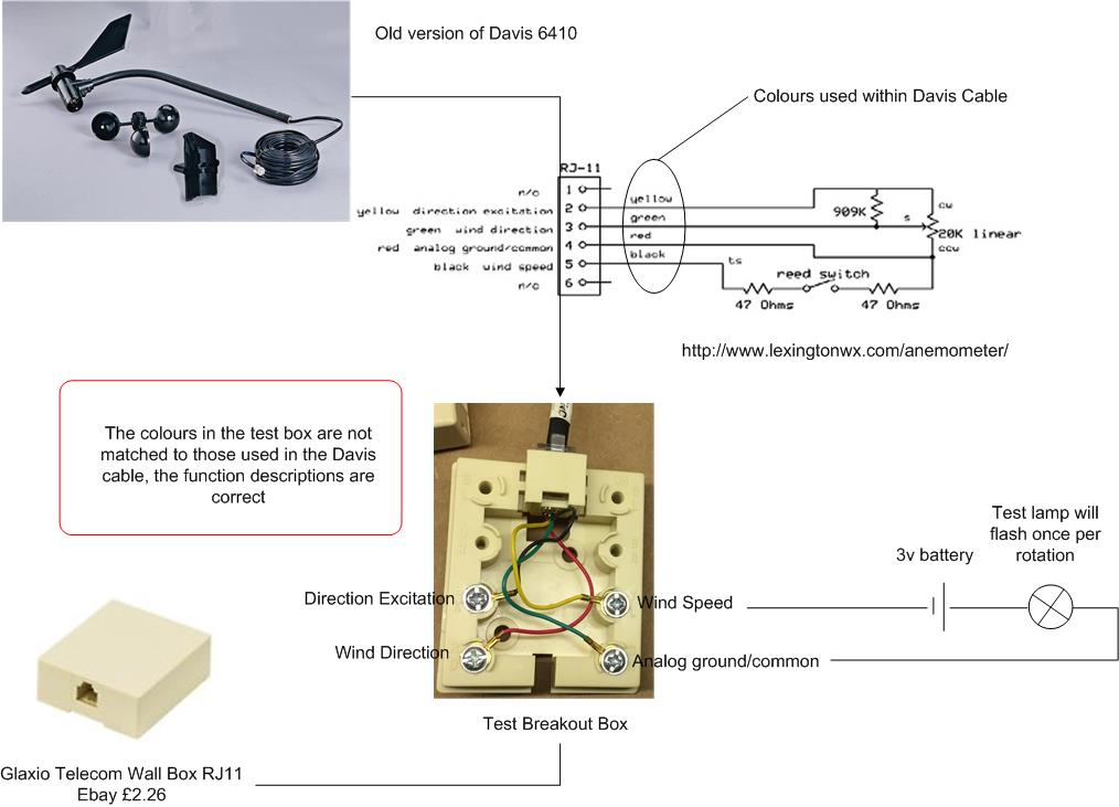
Davis 6410 Anemometer
25 October 17 my wind speed sensor failed after 9 years service, the symptom being that the wind speed is always at zero after checking the connection to the ISS is tight and the cable to the anemometer is not damaged.
This is the blog is how to replace the reed switch and test its operation, also while it was in bits, I thought I’d take the opportunity and replace the bearings as well.
Information Sources
Online sources of information relating to replacing the Davies 6410 reed switch –
- http://www.lexingtonwx.com/anemometer/
- cjoint.com
- cdn.manula.com
- 6410 User Manual
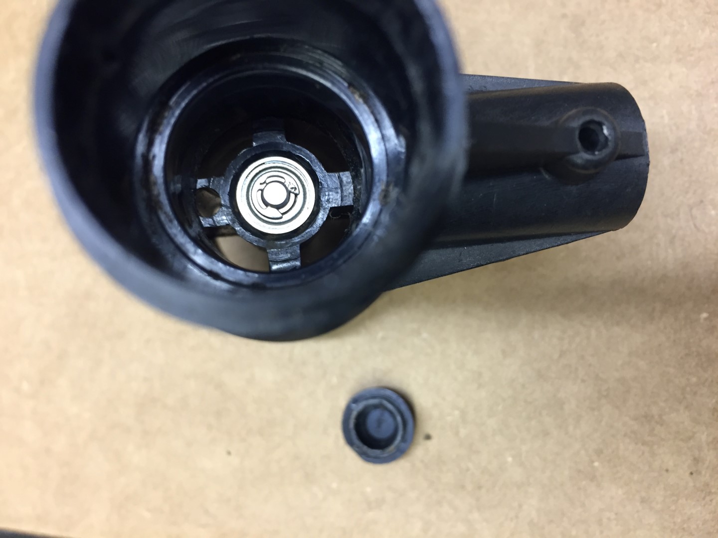
Parts Used
Magnetic Reed Switch 10mm MKA-10110 100v 0.5A Russia £3.50 for 10 from eBay.
Metal Shielded Bearing 0.125 x 0.375 x 0.156 Part R2zz £0.85 each from rcbearings.co.uk
Tools Required
- Pliers
- Sharp knife
- Marker pen
- Phillips screwdriver
- 1.25mm or 0.05″ allen key
- Soldering Iron & Solder
- Magnifing Glass
- Terminal Screwdriver
- Glue gun (or similar adhesive)
- Multimeter or battery & lamp.
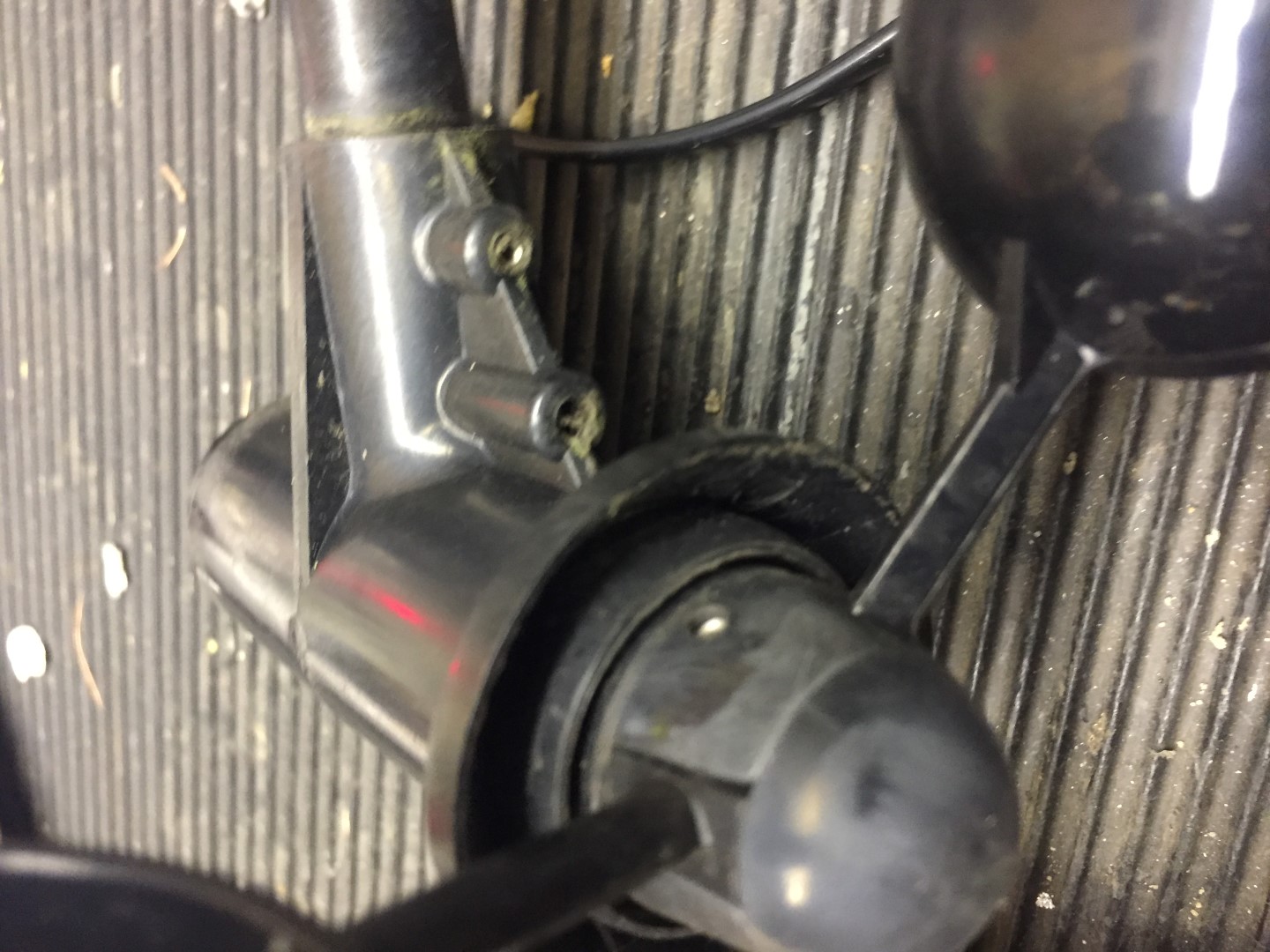
Step 1
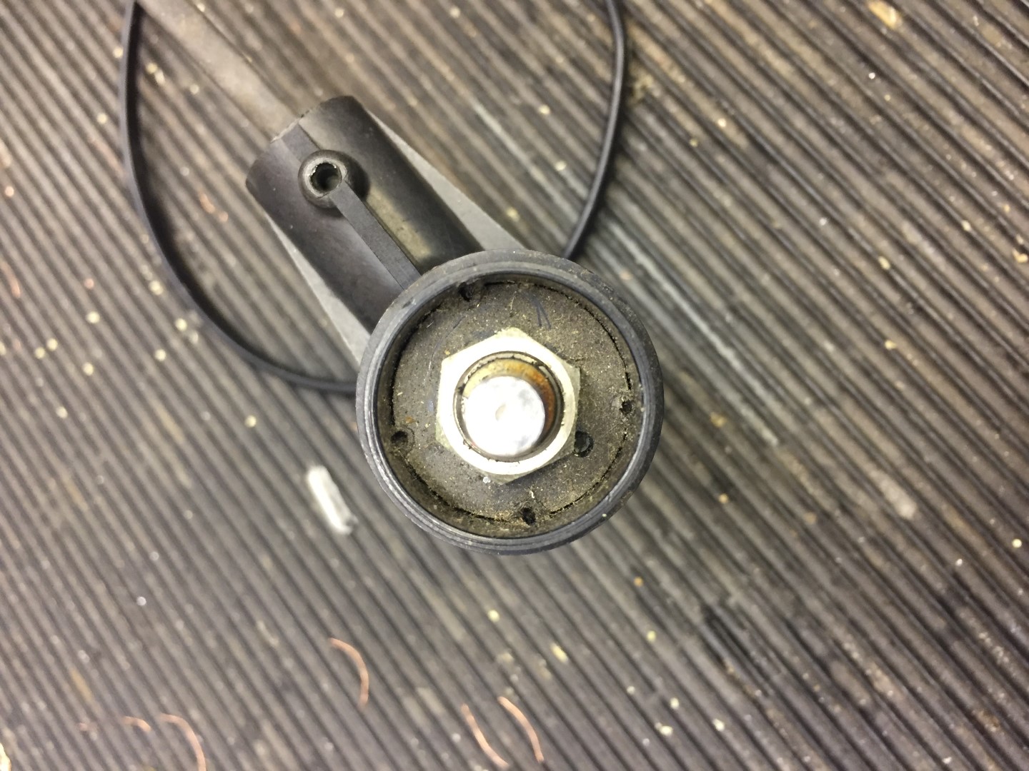
Remove the vane and wind speed cups to avoid damage.
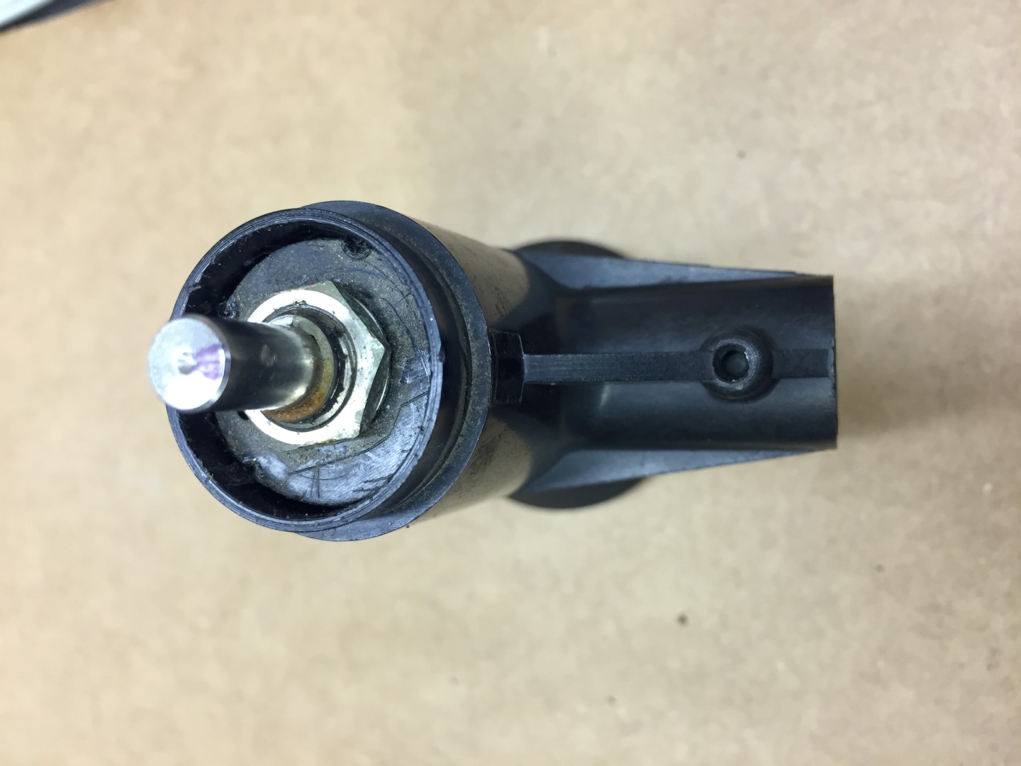
Undo allen screw, if tight, use penetrating oil first, the screw does not need to come out.
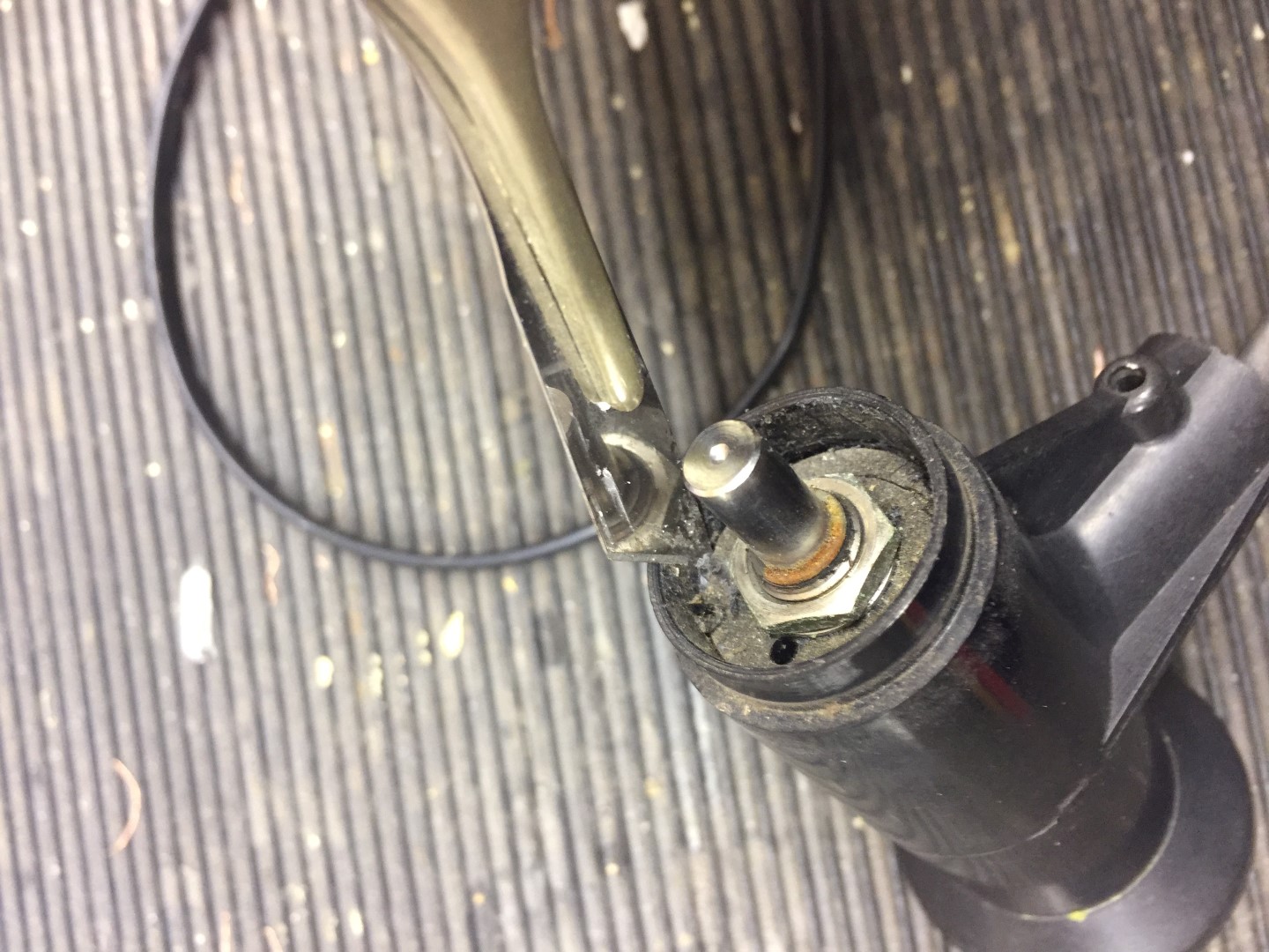
Once the allen screw is loose, the vane is an interference fit, and with a little gentle force, pulls up revealing the potentiometers (pot) shaft.
The shaft is not ‘keyed’ but will have a mark where the allen screw tightened against, when you reassemble, use this to align the vane so the screw tightens in the same place.
I marked the shaft showing the allen screw mark, I also marked the body of the pot in relation to the housing so that when I reassemble everything is in the same position and the wind direction reading will not be out.
Step 2
Using the same allen key, undo the securing screw on the wind cups, once loose, the assembly slides off the shaft with little force.
Put the wind cups and vane in a safe place till later.
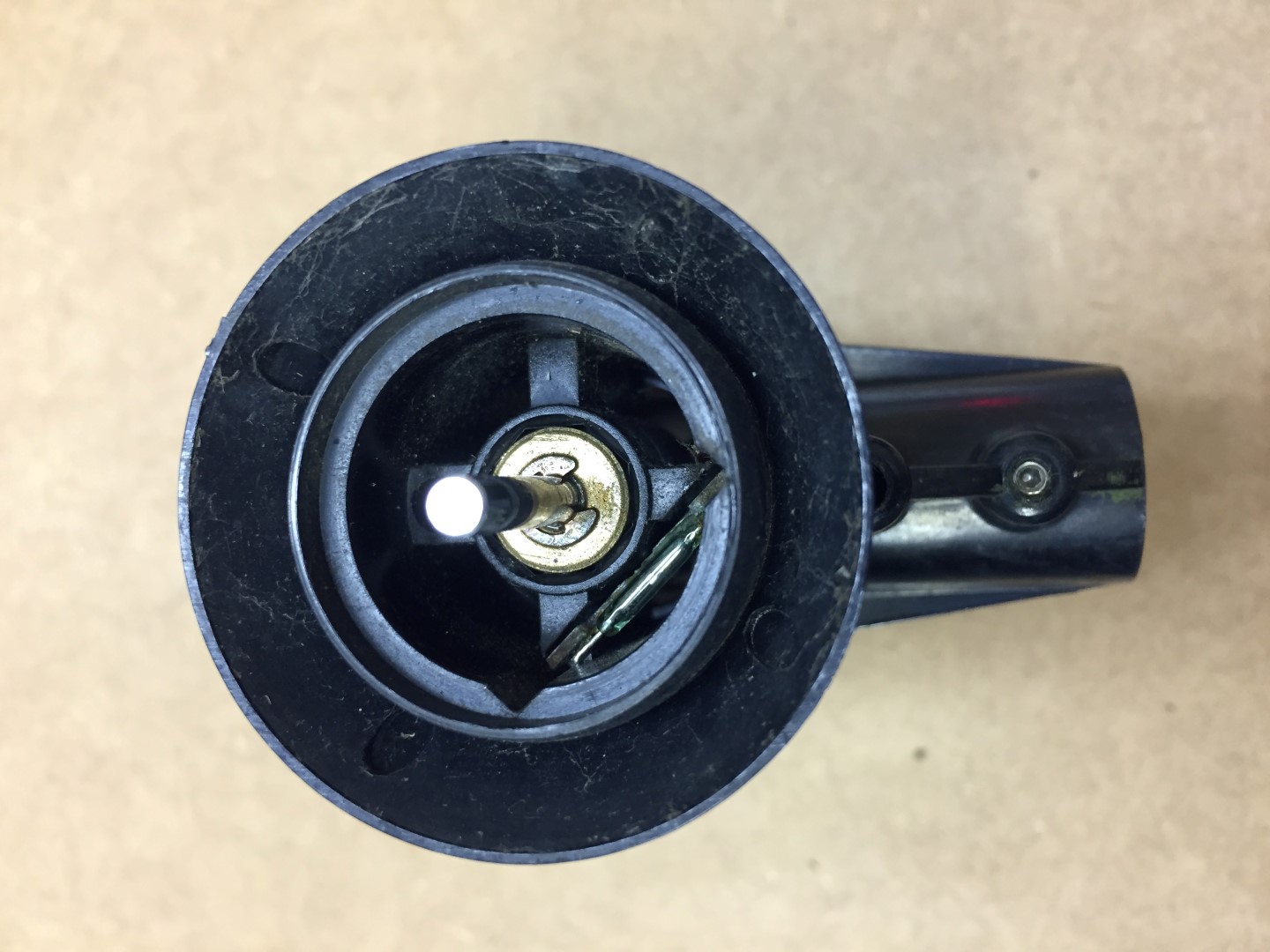
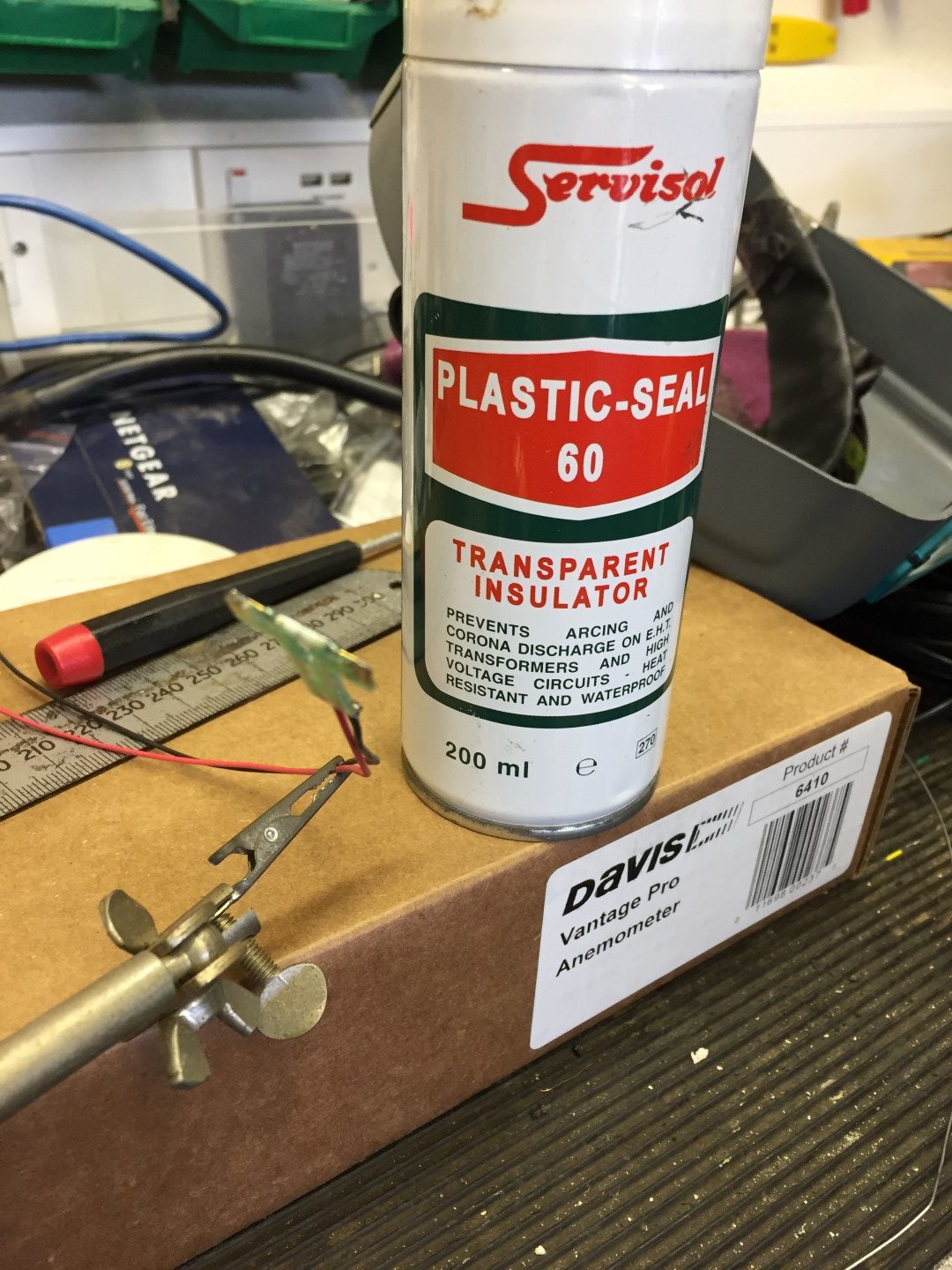
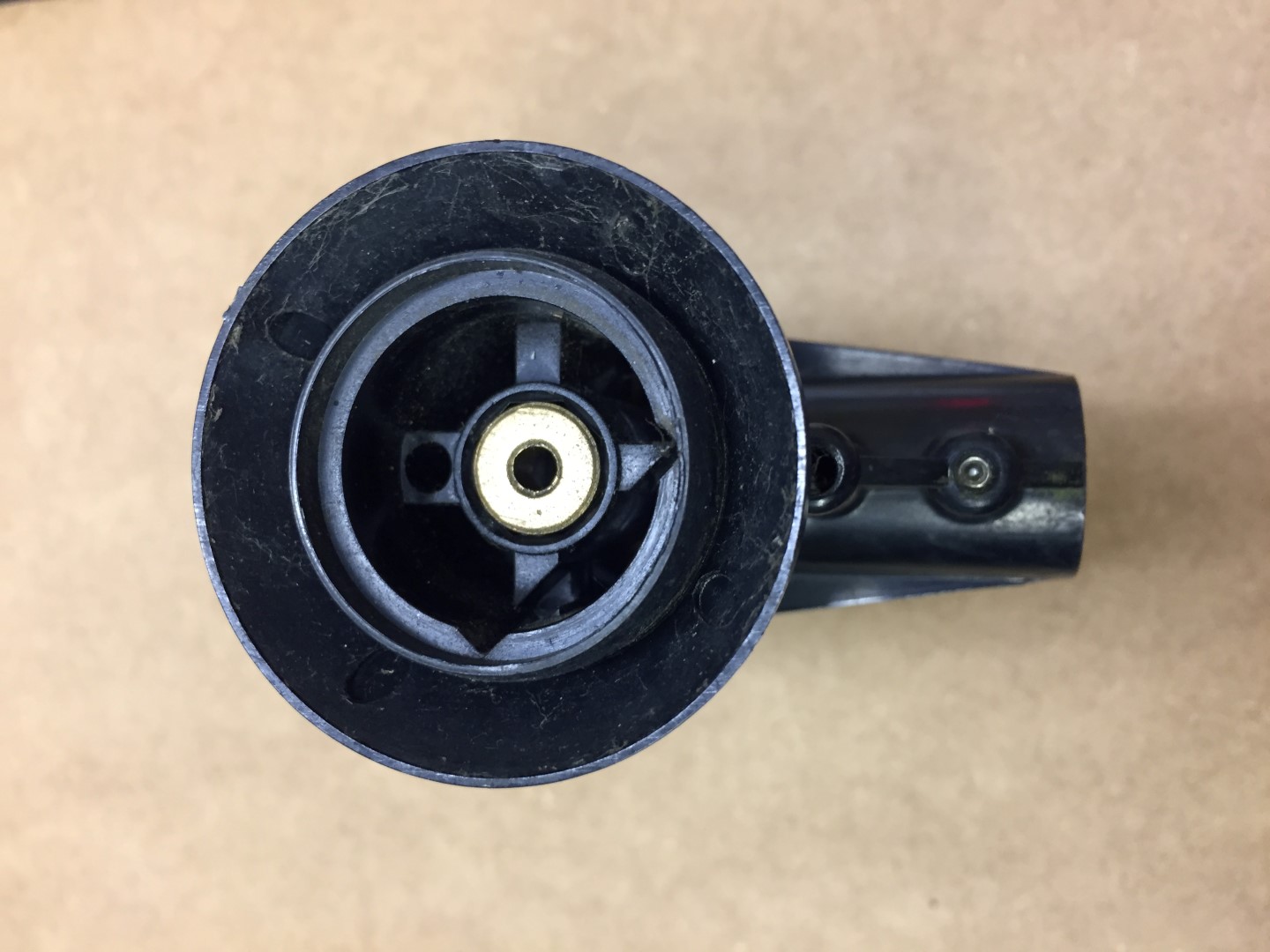
Removing the wind cups reveals the reed switch which can only be accessed by removing the pot.
Step 3
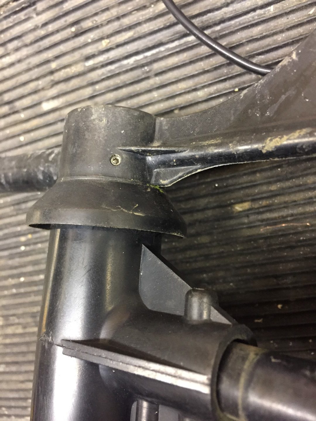
Breaking down the arm and releasing the cable, this is important when we come to remove the pot.
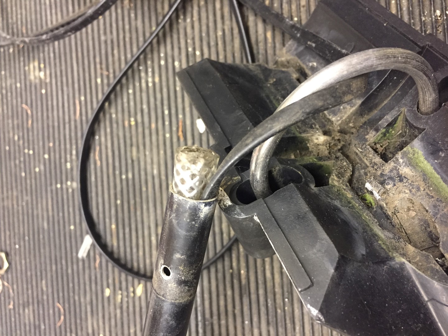
Undo the machine screw and slide this out, once the cable has been released from the in-built grips of the mounting bracket, the tube should slide out of the housing.
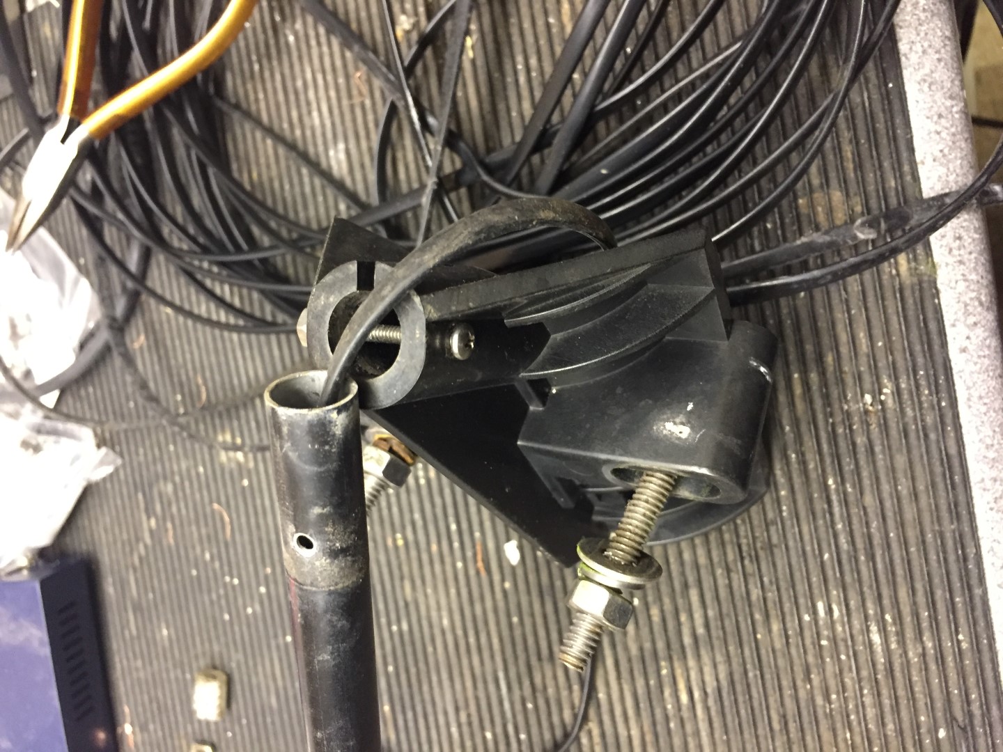
The cable inside the tube has a crude cable grip made from an off-cut of plastic hose, either use pliers or a wood screw in the center of the hose, and gently tease it out.
The next part is to slacken the two allen screws which hold the wind and direction body to the arm, once done, slide the arm down the cable to give you working room.

Step 4
Removing the pot, this is a push fit and held in place by hot melted indents, these need to be cut away with a sharp knife.
Once the indents have been cut away, the pot will pull out of the housing, NOTE – this is a tight fit, use pliers to hold onto the pot shaft and draw towards you, Warning – I pulled too hard and pulled wires off the pot as their is not much slack in the wires from the reed switch, it’s not the end of the earth if you do though as I cut them off anyway!
Step 5
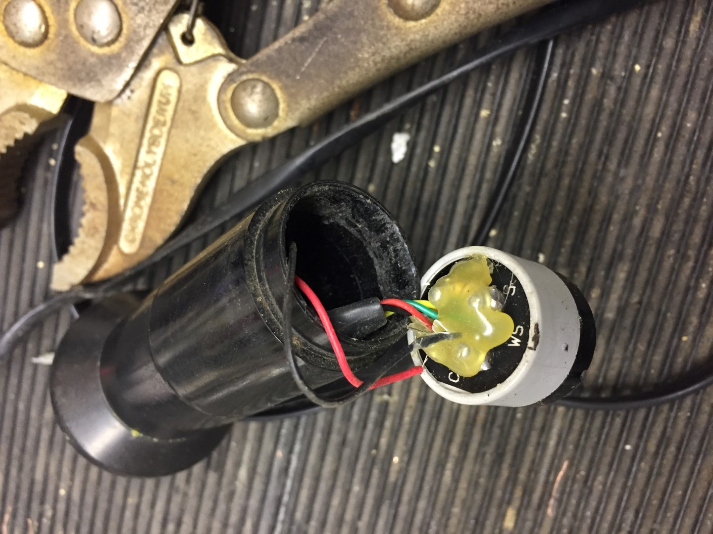
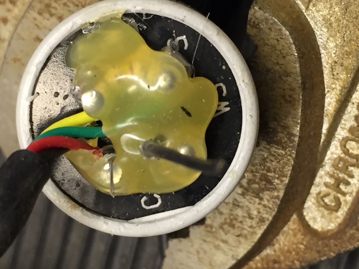
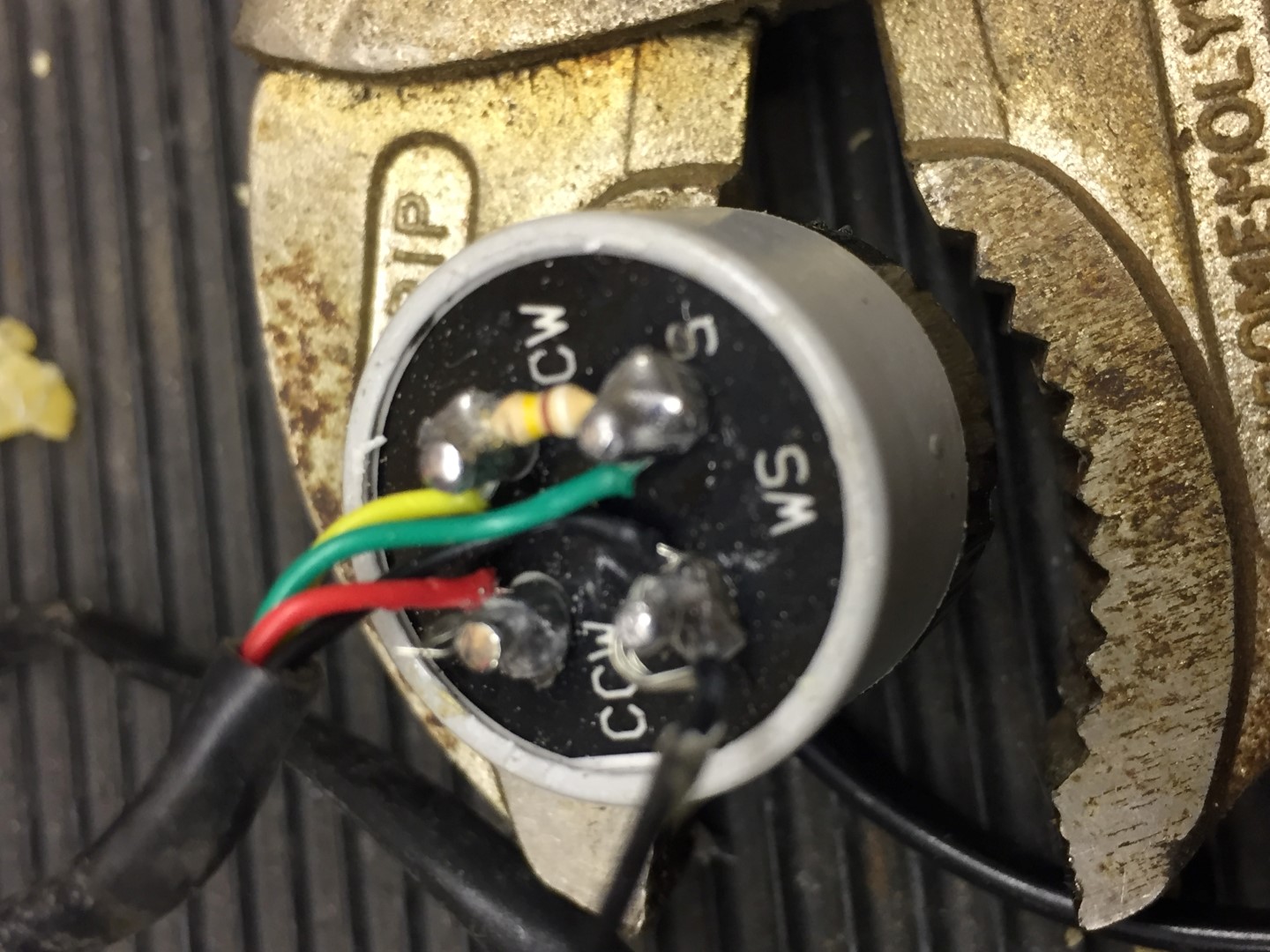
Remove the gunge from the rear of the pot and note which colour wires go where, the red and black fly lead go to the reed switch and these I cut, I also cut all wires to the pot and removed this so I could easily work on the reed switch and bearings.
Step 6
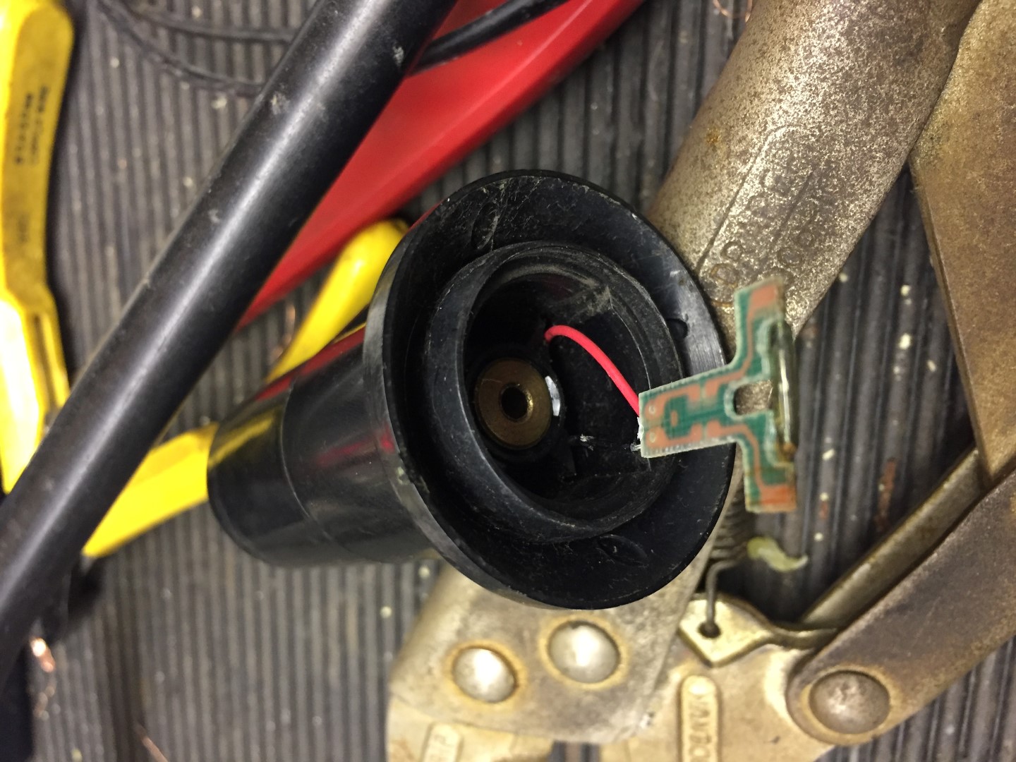
The reed switch is held in place with the same gunge (hot glue?) as is on the rear of the pot, due to aging it had gone brittle, using a terminal screwdriver it was possible to break this up from inside the housing body.
Once glue is removed, the reed switch assemble will slide out.
Step 7
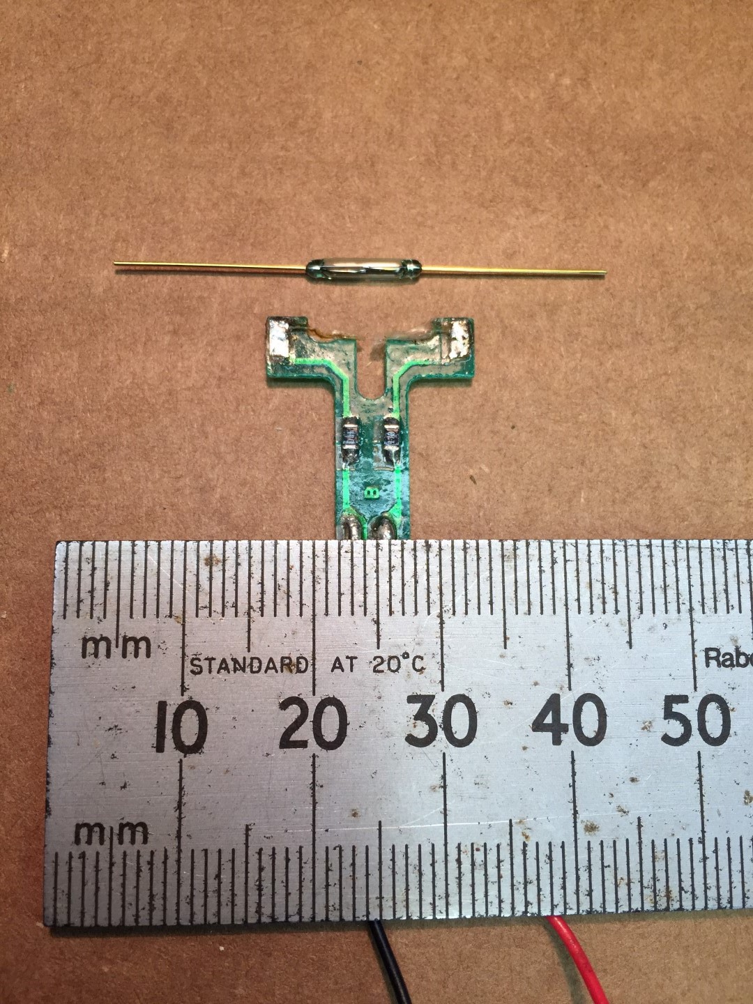
Reed switch replacement, the reed didn’t appear to be visually damaged, only slight rusting. Testing with a meter and magnet, the reed flexed but no electrical contact was made, checks on the circuit board tracks and resistors were OK.
The zoomed pictures make things look easier to handle than they are, the picture below offers some scale.
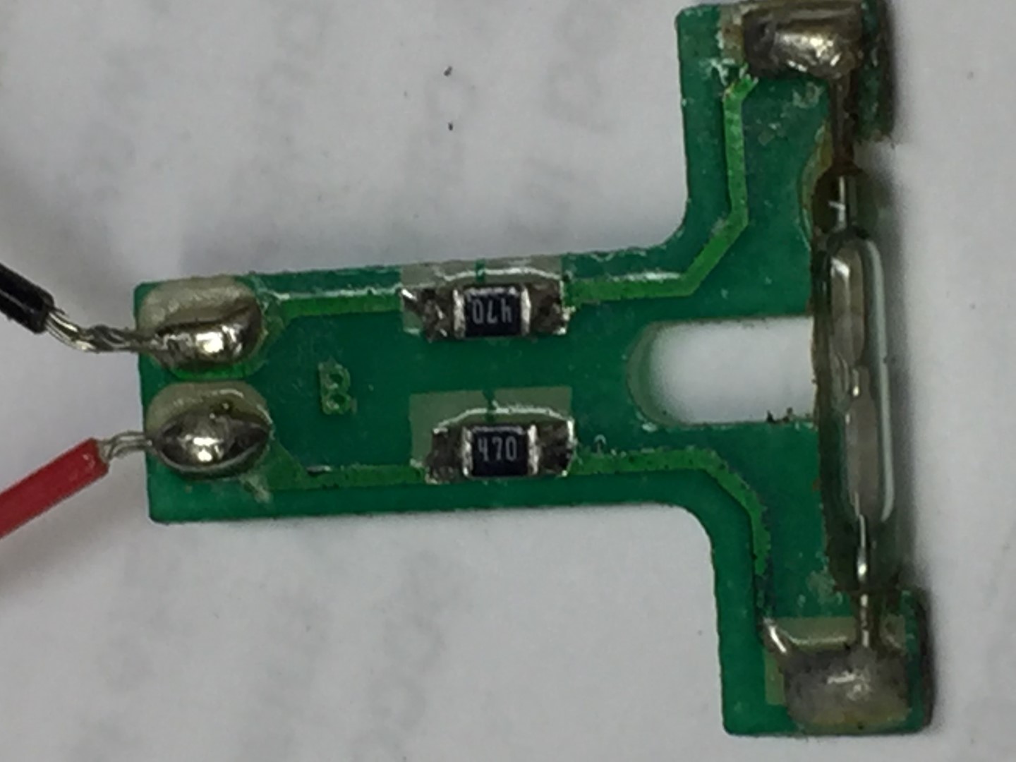
New reed soldered into position with the contact leafs horizontal to the orientation of the PCB, I also replaced the Red and Black wires from the PCB with more flexible ones.
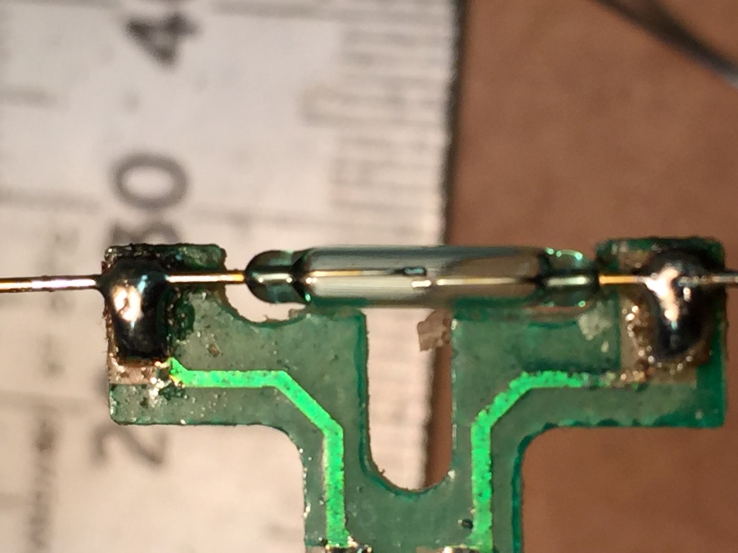
Once the reed switch excess wire was trimmed, sliding the PCB into the housing body and getting it flush broke the reed.
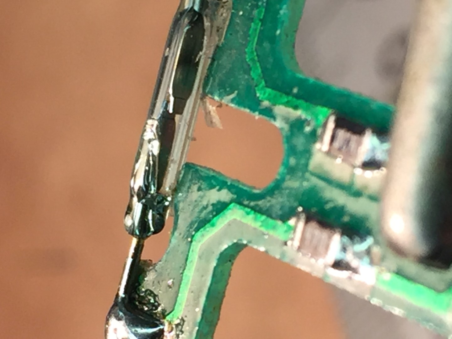
The cause was the reed needs sit,as flat as possible,inline with the PCB, I had used too much solder and this lifted the reed wires slightly off the PCB.
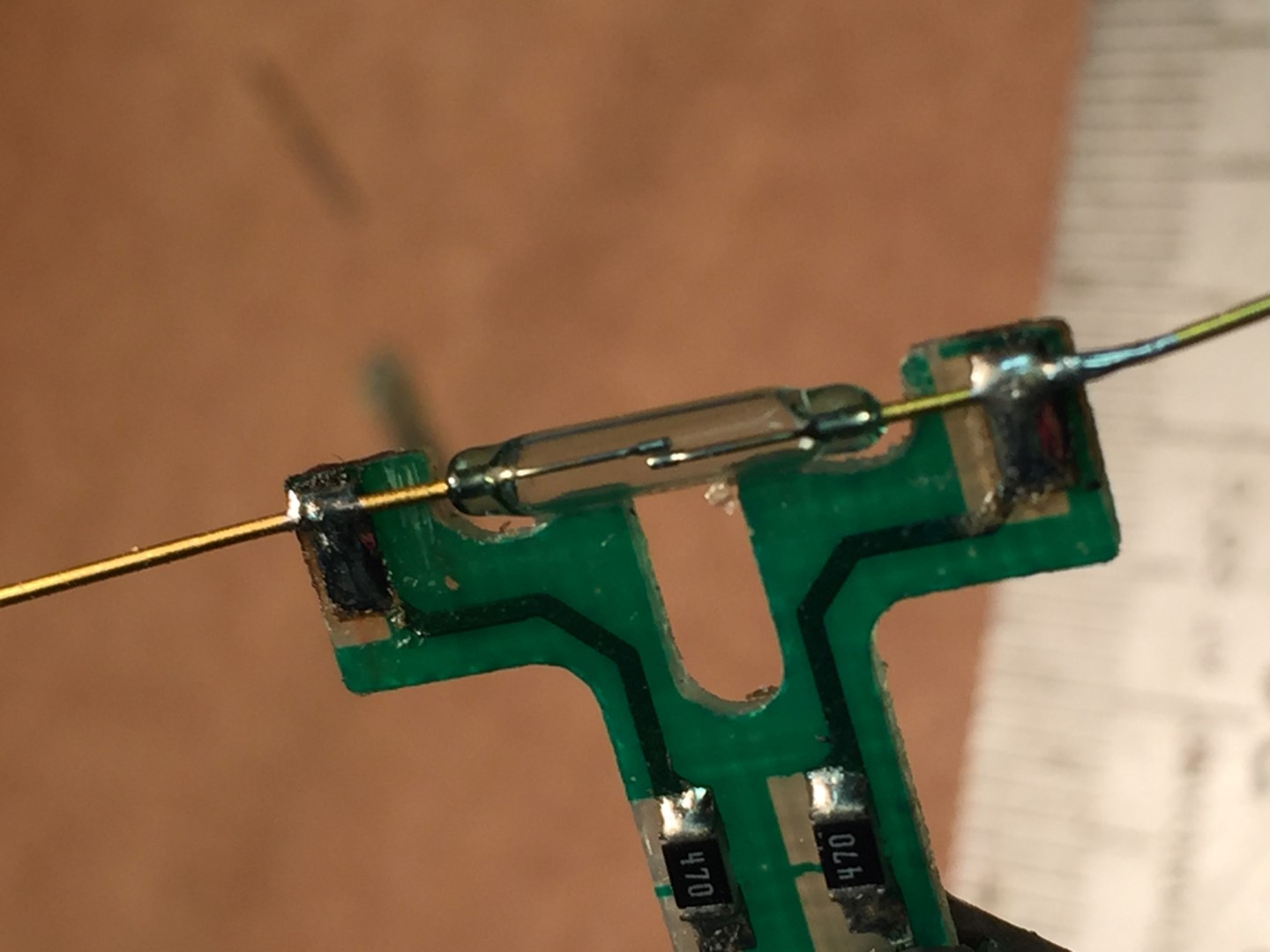
The picture below is the second attempt where I used minimal solder on the PCB pads and pressed the reed wires onto the pad before using a small amount of solder to connect to the pad. This seems to have worked and allows the PCB to slide into the housing and sit flush once the wires were trimmed.
After sliding the reed switch in the body, I connected a multi-meter on continuity buzzer setting, sliding on the wind cups and spinning them, this should cause the buzzer to sound once on each revolution.
Once correct operation is proved, remove the wind cups and reed switch assembly, I sprayed the reed switch with a protective coating and put them in a safe place until later.
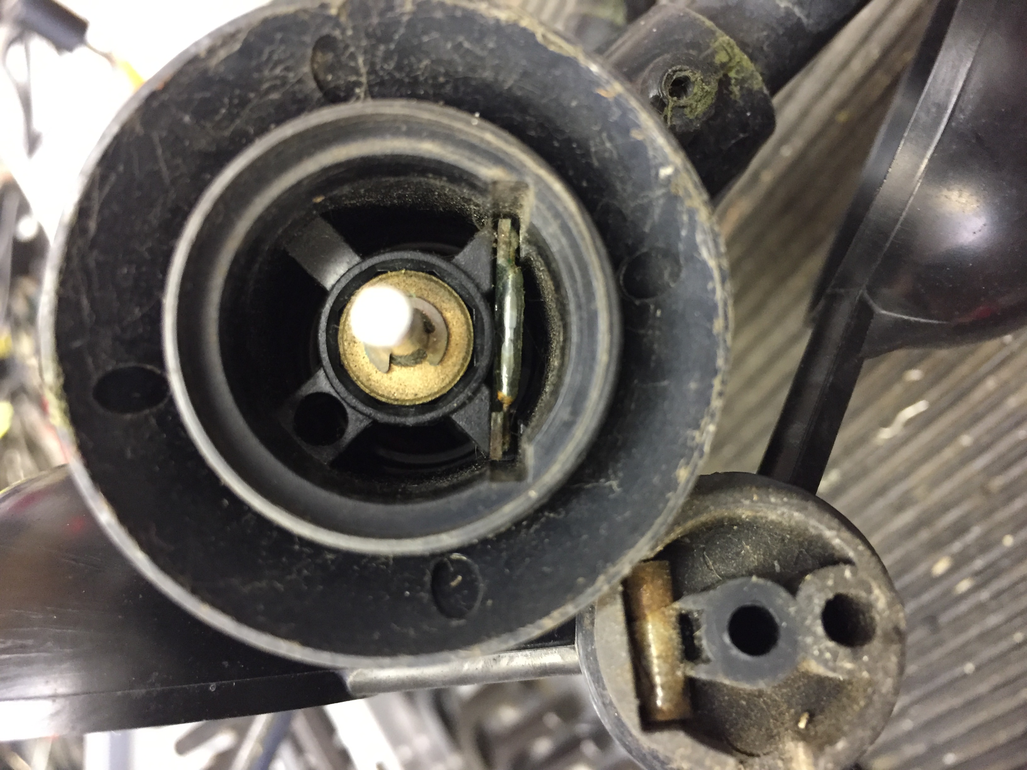
Step 7
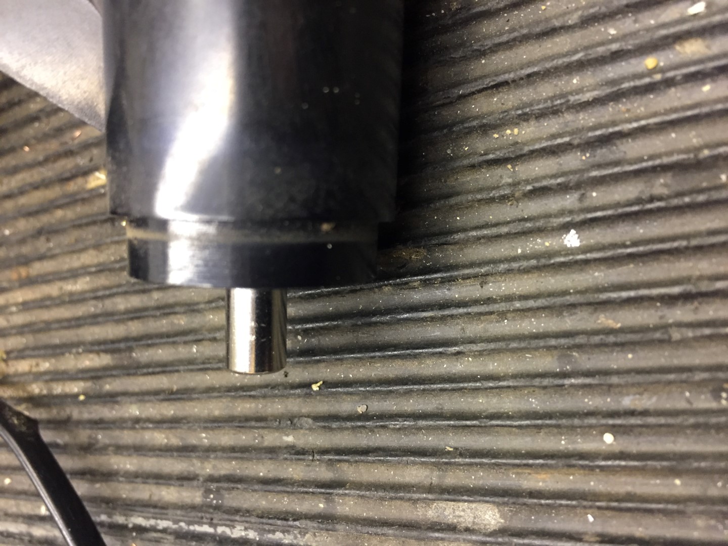
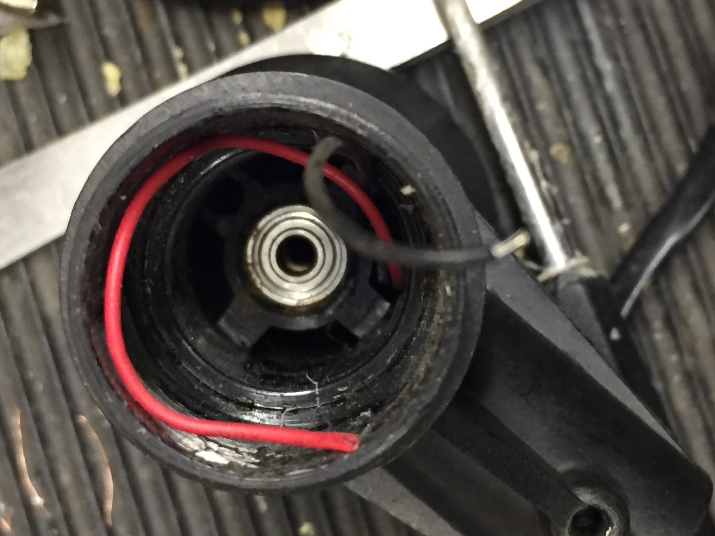
Replace the wind shaft bearing, first the circlip needs removing and retaining for later use, once the clip is off, the shaft can be pushed into the housing.
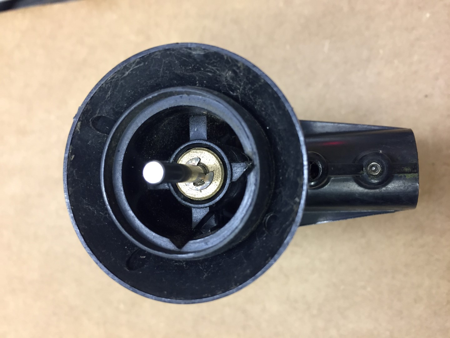
The shaft and black cap can now be removed.
My model has the brass follower looking from the cup side, other pictures I’ve seen show this to be the bearing with the brass follower inside the body, I reassembled in the same order as I took apart.
To remove the bearing, I left the brass follower in and used a terminal driver to go through the hole and using it at a slight angle, gently tap against the underside of the bearing, moving around the inside of the bearing and tapping to tease the bearing out of the housing.
The old bearing is in the bag and it is in good condition with only slight signs of rusting.
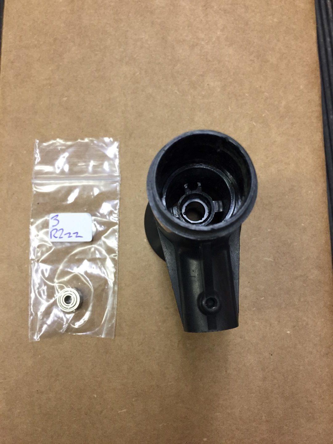
The new bearing simple pushed into the housing.
Step 8
Reassembly:
- Slide shaft into place and fit circlip, make sure the shaft spins freely, I applied a light oil to the brass follower only.
- Slide the reed switch into place and making sure that it sits flush, after putting the bearing protective cap on and I then used hot melt glue from inside the housing to secure everything in place.
- Checking that the cable is still threaded through the arm, pass the cable into the housing ready for soldering onto the back of the pot.
- Once with wires are back in place, I sprayed a protective coating on the pot and pushed it back into the housing checking that the marks I made at the start are aligned.
- I didn’t melt fix the pot, the protective costing will act as an adhesive.
- The arm was then re-affixed and secured.
- The arm cable grip was pushed back in, check that the fixing hole is clear for the machine screw when pushing the grip back in.
- Fix vane back on to pot, aligning grub screw with marking on shaft.
- Fix wind cups onto shaft.
Testing
I used a Glaxio Telecom Wall Box RJ11 which cost £2.69 from eBay as a breakout box for testing that the reed and directing pot are working:
My old 6410 is now refurbished and will be stored in the loft until the one in use packs up.
If you need any further information, please contact me.
This is nicely done and well documented.
I am working on a Vantage Pro (1) (date – about 2003) and doing some of the same restoration work. My main problem is finding the humidity capacitor used in the shielded chamber to measure outside humidity. My humidity and temperature are analog outputs. But they are separate devices.
The temperate seems to be some kind of thermistor bead and the humidity is a separate humidity/cap which has two legs and is a cap sensitive to the presence of water vapor. The cap was common in 2002 but is no longer made by Honeywell.
If you have any ideas I would be interested. It would be so nice to have schematics for these old systems!
Steve
Hi Steve,
I don’t have any experiance of the Vantage Pro 1 as mine is a VP2, looking through the WX forums it looks like support is very hard to come by for the older versions – https://www.manula.com/manuals/pws/davis-kb/1/en/topic/older-davis-stations.
If I do come across any info, I’ll post it up.
Just a remark: I have used a KSK 1A35-1015 as replacmant rees switch. The whole prodedure worked fine, bnut finaly i realized, that the redd switch give a signal on both sides, whe I rotate the wind cup. this double the wind speed , I thionk, the reed switch is probably to sensitive. By fixing a self sticking cupper foil oposite of the magnet, on the wind cup, it is now working fine.
Thanks for checking out my blog and I’m really pleased you fixed your wind speed reed.
Hello,
thanks for your well documented repair, i am repairing ( if possible !) an old weather monitor 2, the wind speed stopped
so i have stripped it down, it has a vertical magnet (mountd in the spinning cups) and the reed switch is mounted in a gooey silicone like stuff , im assuming it would be the same reed switch as fitted to the PCB in your repair ?
I have brought 2 ! one as a spare
It is mounted vertically in the goo in the plastic body rather than horozontaly does that sound ok ?
many thanks
Nick
Hi Nick,
Thanks for checking in, yes this sounds right, the magnet and reed switch in the same orientation, this should work just fine.
Ian
I just ordered a new wind gauge for my V2 this morning ($250 Canadian). Was hoping to be able to repair the old one to keep as a spare. Your blog is going to come in handy in a few weeks.
In my case, it’s the bearing on the anemometer that’s packed up (I can rotate the cups one or two turns by hand before it will catch up every time); but I think while I’m at it I’ll likely replace it and the reed switch as well.
Fingers crossed you can repair your old unit and keep it as a working spare, good luck and let me know how you get on.
Ian
Greetings,
Thank you for taking the time to write this up and post all the helpful images. I have an old Vantage Pro weather station from 2002 that I’m trying to resurrect so that I can give it to a local elementary school. Sure enough, it was the reed switch that was bad. I was very lucky to somehow NOT have to dismantle the potentiometer (wind vane part) when trying to access the reed switch and just gently pulled on the circuit board with some tweezers to make it slowly come out. I got it out enough to have the reed switch about 1 inch outside of the anemometer housing without disconnecting the red and black wires.
When I checked the continuity across the leads of the original reed switch, it was stuck open and nothing I could do would release it. I ordered a couple new ones from Ebay and then was able to unsolder the old one and remove it and then solder in the new one. Sure enough, it worked! I can say that I looked very carefully at the orientation of my original reed switch to the circuit board and mine was rotated 90 degrees from yours so that the flat part of the reeds were parallel to the plane of the circuit board. I did some testing with the new reed switch before I soldered it in and determine that no matter how it was oriented, it worked fine when I brought the magnet close to it. So I just put the new reed switch in with the same orientation as my old one. Everything is working fine with the anemometer now.
The only thing I have left to troubleshoot is that my display console loses connection with the ISS occasionally (for hours long) and no change in batteries, antenna orientation, or proximity change seems to resolve it. Got any ideas?
Thanks,
Scott from Austin, Texas
CW0133 / KTXAUSTI8
Hi Scott,
Thanks for checking in, glad you got the switch sorted and really good that you managed the repair with limited disassembly.
I can’t help unfortunately with the connection drops as I have the wired version, maybe the folks on WX Forum will be able to help.
Good luck with your projects.
Ian
For each revolution the reed switch makes two contacts (two ground connections) or only one?
Thanks
Hi,
The unit only has one magnet fixed to the rotating section, therefore, the reed switch operates once per revolution.
Hope this helps
Ian
Hi there,
anybody know how to buy a replacemen 20k potentionemeter? Mine has gone.. 🙁
thanks
Hi,
I thought these were made for Davis but stand to be corrected.
Hi,
thanks for the report, anemometer successfully dismantled, now waiting for the new reed switch
Thanks for checking in, glad its getting sorted.
Struggling to cut away the “hot melted indents” in order to remove direction pot. The black plastic covering seems very hard. Would a small holesaw work?
What do these “indents” look like when removed? Do you have a photo?
Better still, do you offer a repair service for the anemometers and ISS assemblies? I have three of each with various faults and I’m fed up with the expense of regular replacements. PCBs are not my speciality.
Can’t believe your anemometer lasted 9 years – mine only survive two years or so before developing faults! Same with the ISSs.
Thanks for your useful guide and help…
Hi Jez,
The indents look like they are made with the tip of a hot soldering iron just pushed in to the plastic to make a melted indent to hold the pot, unfortunately I don’t have any pictures of it removed, but the indent or plastic nipple does not extend far and I used a sharp craft knife to cut through the plastic and it worked ok, a holesaw would work but be careful you don’t remove too much material, I suppose a dremel could be used as well.
Thanks for having the confidence in me that I could fix things, I got lucky this time 🙂
Good luck and let me know how you get on.
Cheers
ian
I have a small info about the Temp sensor ASSY07315.176A RevA 00 from 2006
Instead of buying a new one remove the rubber that covers cables and C41 i found water had been under so the C41 was grey and partly shortned after cleaning and sprayed the board witch protection it works perfect
I have a photo but cant post it here
Hi Lars,
Great result you had their, well done for spotting and resolving the problem
Hi Ian,
Thanks for the excellent instructions on repairing a Davis anemometer. Mine failed after 10 years service. I bought a replacement, which cost me £150 (ouch!) but then found your excellent article, which I followed more or less to the letter, although I didn’t replace the bearings.
My eyesight is not good these days, and soldering is now virtually impossible, but with a lot of care and patience I succeeded in replacing the reed switch. I did break the original reed whilst extracting the PCB and then went on to break the replacement reed on re-assembly, but had better luck the second time, being careful to push the PCB only on the outer edges.
I did find that I need not have removed the pot, as the red and black wires on the reed assembly were long enough to enable the PCB to be pulled out far enough to work on. Having re-assembled it all, I used your test suggestion of the Glaxio breakout box only to find that the yellow wire had broken off the pot. A bit more difficult (for me) re-soldering and all tested OK.
If I ever have to do it again, I would make sure that having removed the reed PCB and unsoldered the reed, that the PCB would slide easily into the grooves at each side before mounting the new reed.
My anemometer does not have the 909k resistor shown on the diagram, so maybe this was an addition on later versions. I turned the pot to the point where it was open-circuit and re-fitted the vane pointing north. If this repair procedure works for the later versions with a d-shaft on the pot, it would be important to re-insert the pot in the same position as ti was removed.
Thanks for taking the trouble to write this up and taking all the photos.
Ray
Hi Ray,
Glad it was of some help and great news that you sorted it out and have a spare for 10 years time 😊
Thank you for this comprehensive guide! I was able to follow it to replace the reed switch in my 14-year-old Vantage Pro2 anemometer here in Australia. The reed switch I used was S5150A from Altronics; it has the same dimension as the original but is low voltage which seems to be fine for this application. I didn’t replace the bearing because it seems to be going fine.
Hi Debbie
Glad the blog helped, just imagine how many times your 14 year old reed switch opened and closed, just mind boggling.
All the best
Does anyone have a replacement for the pot? Mine is real intermittent in the NW quarant.
Hi Mark,
Sorry I don’t know where you can get a replacement pot, you probably already know weather forums and UK suppliers of kit, but for completeness I’ve included links in case they may be able to help:
WXForum
Weather Display
Prodata
Weather Shop
Good luck with your search and please let me know how you get on.
Thank you for the great instructions on replacing the reed switch and bearing. I’ve had my Vantage Pro2 for around 15 years and this is its first major repair. Thanks for the effort you went to in making this information available.
Cheers
Dave Emery
New Zealand
Hi Dave,
Thanks for getting in touch, glad it helped.
The anemometer pot can be obtained from Scaled Instruments. The link to that item follows:
https://www.scaledinstruments.com/shop/davis-instruments/parts/vantage-pro2-parts/anemometer-parts/davis-7802-031-pro2-anemometer-wind-direction-20k-ohm-potentiometer/
It includes the nut and washer. This is compatible with both the old and new versions of the Davis Vantage Pro 2 anemometer.
Great info, many thanks for sharing.
Hi Ian,
I have attempted to change the 20k Potentiometer in my VP2 Anemometer (new version) but, unfortunately, it appears there is no way to do that with the new version. At least, I haven’t found a way to disassemble it, yet. The potting compound they use is incredibly difficult to remove cleanly as it is kind of rubbery and sticks to the circuit board the pot is attached to. If you or anyone else knows how to remove the pot without destroying the housing, please post it in this thread.
Thanks,
Don – w3drm
wx website: https://emmettweather.com
Hi Don,
I wish I could help, hopefully someone will chime in or maybe the WXForum may be able to help.
Good luck
Ian,
Thank you for your excellent instructions and details on this procedure. I needed to replace my bearing and your guidance was a great help. Davis said I had to replace entire unit for $260. plus tax and shipping. With bearing number you posted I was able to find and got five bearings for $8.
Sincerely,
Ken
Hi Ken,
Thanks for getting in touch.
Really pleased I helped in some way, glad it all worked out.
Ian
Thanks for posting this. Just fixed an old Vantage Pro2 with no wind speed reading. Had to ship the part from the US to NZ but we’re operational again.
That’s great news Matt, glad it all worked out.
Great guide, although I came across this post after my anemometer was repaired. I replaced the concatron, and the wind speed reading is back, but I’m having a problem. The reading is twice as high as it should be. I currently have three Davis stations, and only the repaired one has excessive wind speed. What could be causing this? A resistor that needs replacing?
Hi and thanks for checking out my blog.
If the cup size setting hasn’t been changed either physically or in the Davis settings, I’m not sure why it would read higher due to a reed change, possible damage to the reed and vibration is causing the contacts to make or the reed is too sensitive and has excessive bouncing, causing the electronics to miscount the pulses from the reed.
To test if the reed is damaged you could try tapping the unit without the cups moving to see if any wind speed is recorded, or alternatively, try the repaired unit on one of your other stations to see if the problem moves with the anemometer, if this passes the test, try a new reed.
Hope you manage to get it sorted.
I see a couple of comments on the incorrect speed detection of the anenometer and saw similar and worse when I replaced the reed by ones I had already and in theory were the same sensitivity. Using the original magnet I was getting 3 readings per revolution and after a lot of frustration found that it overly sensitive the reed was seeing the huge variability you can see in a magnetic field (I’ve had similar issues with hall effect sensors), and had to replace the magnet with a much smaller one until only the ‘tip’ of the magnetic field was sweeping across the reed and that gave me the one pulse per revolution back. I also had a slightly oversized reed which did not help in the fitting of the reed.
Great info Robin, thanks for sharing.