
Link to WXForum excellent article on Anemometer and Vane – HERE
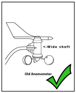
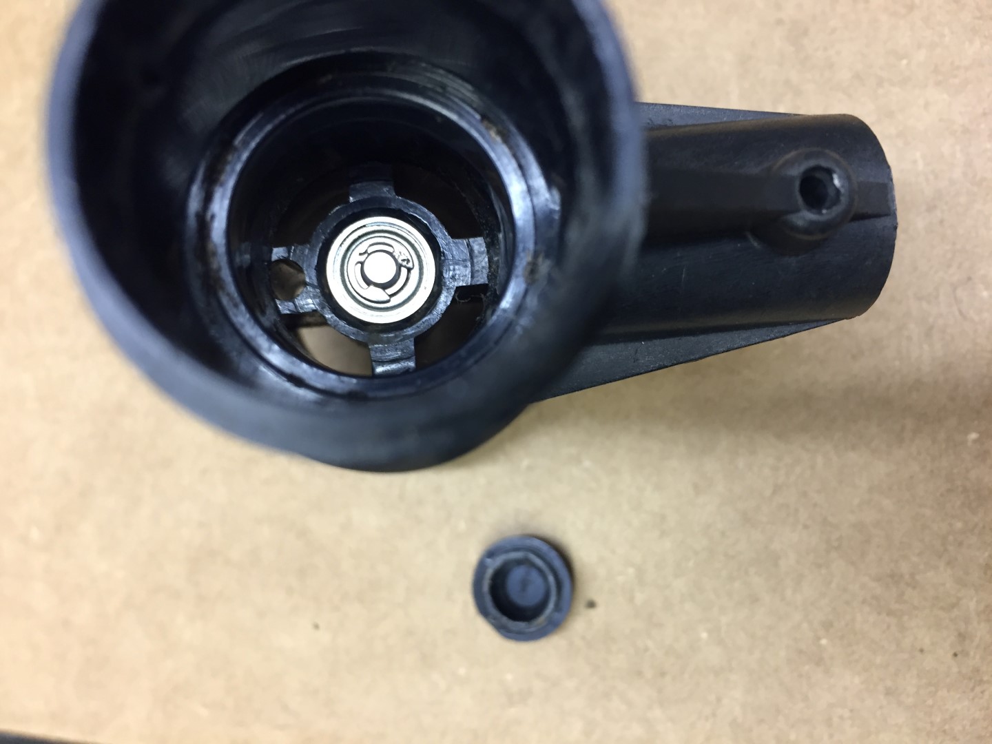
Davis 6410 Anemometer
25 October 17 my wind speed sensor failed after 9 years service, the symptom being that the wind speed is always at zero after checking the connection to the ISS is tight and the cable to the anemometer is not damaged.
This is the blog is how to replace the reed switch and test its operation, also while it was in bits, I thought I’d take the opportunity and replace the bearings as well.
Information Sources
Online sources of information relating to replacing the Davies 6410 reed switch –
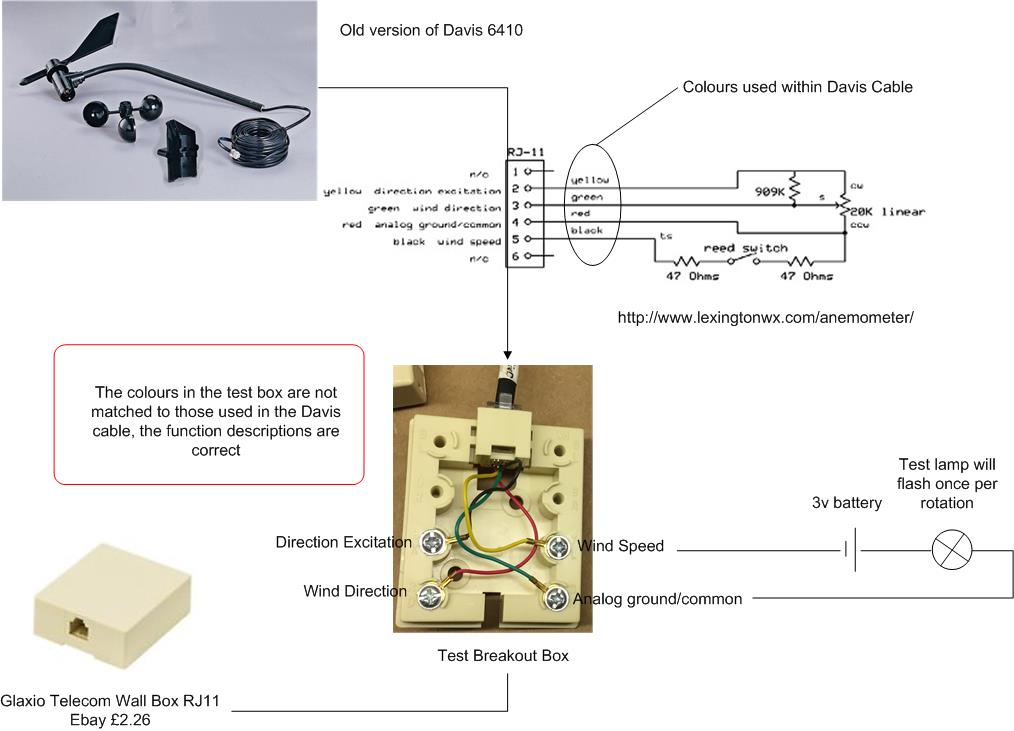
- http://www.lexingtonwx.com/anemometer/
- cjoint.com
- cdn.manula.com
- 6410 User Manual
Parts Used
Magnetic Reed Switch 10mm MKA-10110 100v 0.5A Russia £3.50 for 10 from eBay.
Metal Shielded Bearing 0.125 x 0.375 x 0.156 Part R2zz £0.85 each from rcbearings.co.uk
Tools Required
- Pliers
- Sharp knife
- Marker pen
- Phillips screwdriver
- 1.25mm or 0.05″ allen key
- Soldering Iron & Solder
- Magnifing Glass
- Terminal Screwdriver
- Glue gun (or similar adhesive)
- Multimeter or battery & lamp.
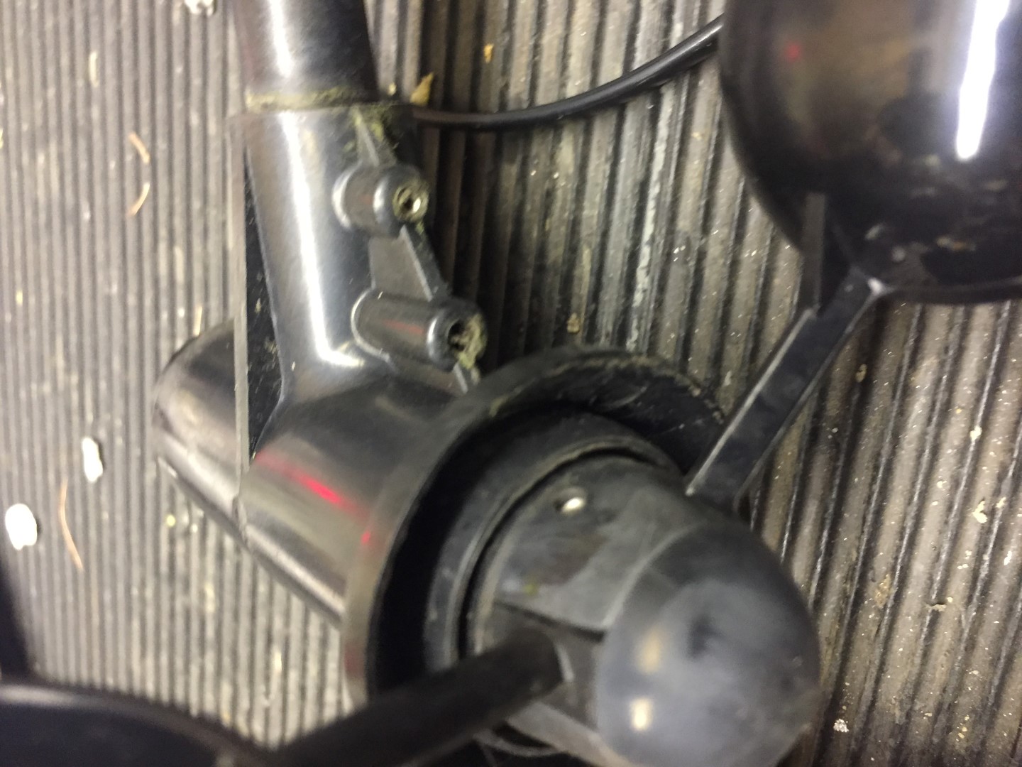
Step 1
Remove the vane and wind speed cups to avoid damage.
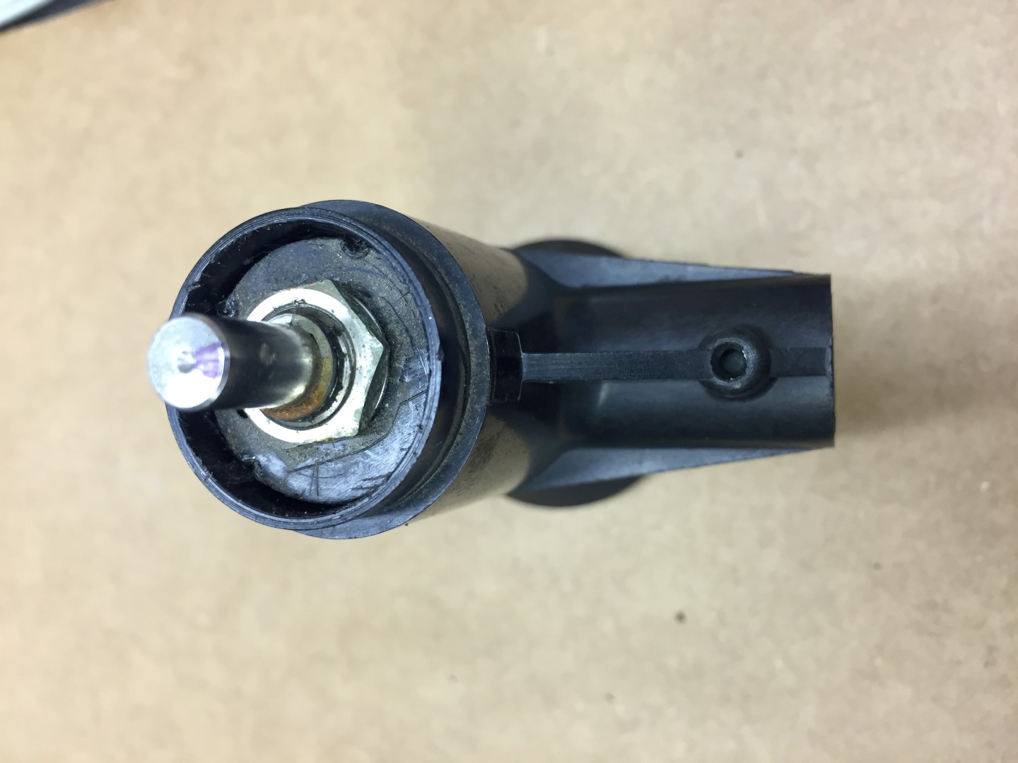
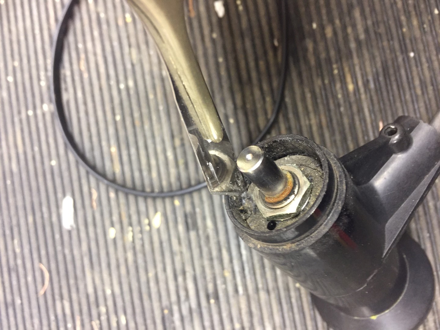
Undo allen screw, if tight, use penetrating oil first, the screw does not need to come out.
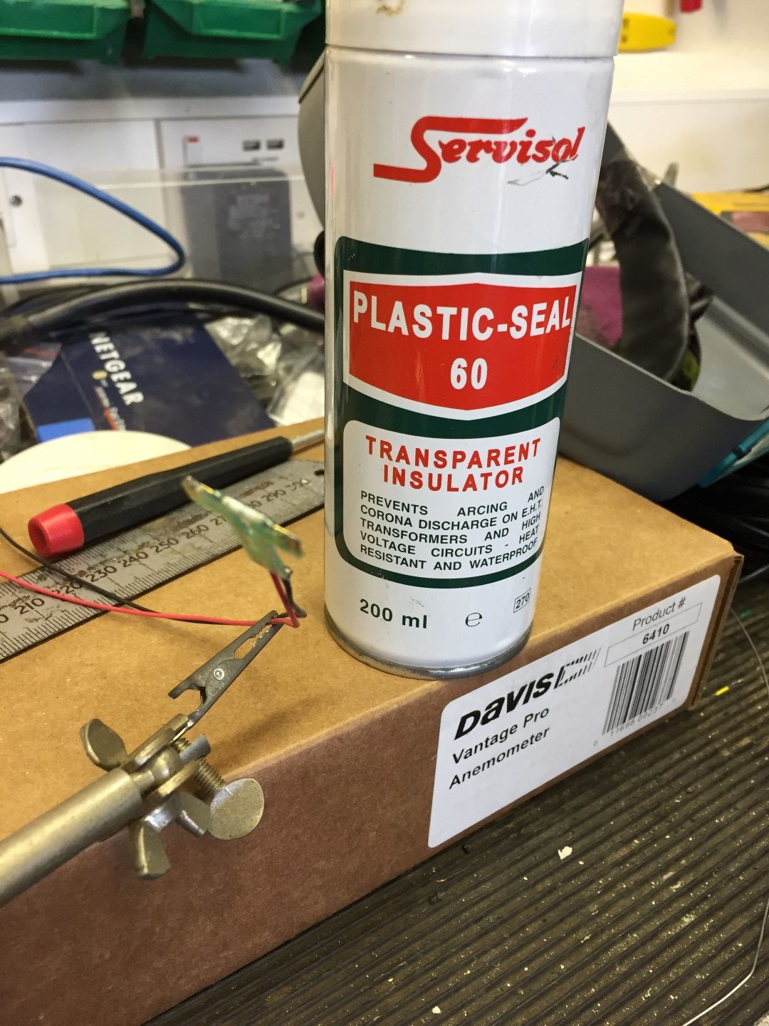
Once the allen screw is loose, the vane is an interference fit, and with a little gentle force, pulls up revealing the potentiometers (pot) shaft.
The shaft is not ‘keyed’ but will have a mark where the allen screw tightened against, when you reassemble, use this to align the vane so the screw tightens in the same place.
I marked the shaft showing the allen screw mark, I also marked the body of the pot in relation to the housing so that when I reassemble everything is in the same position and the wind direction reading will not be out.
Step 2
Using the same allen key, undo the securing screw on the wind cups, once loose, the assembly slides off the shaft with little force.
Put the wind cups and vane in a safe place till later.
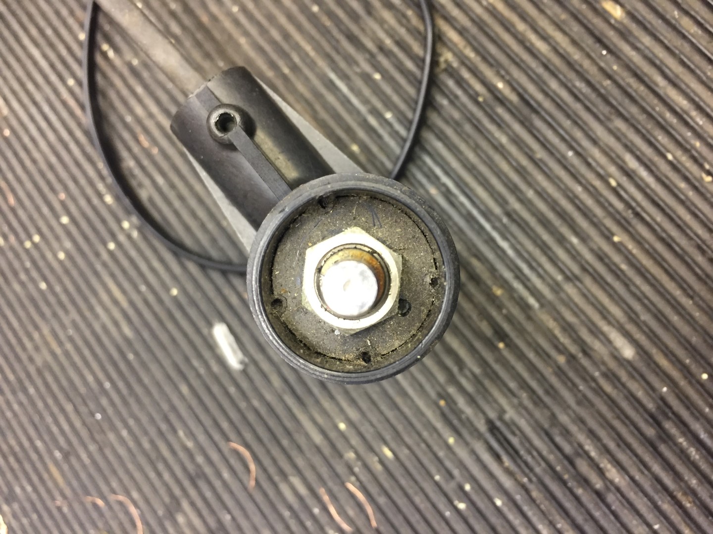
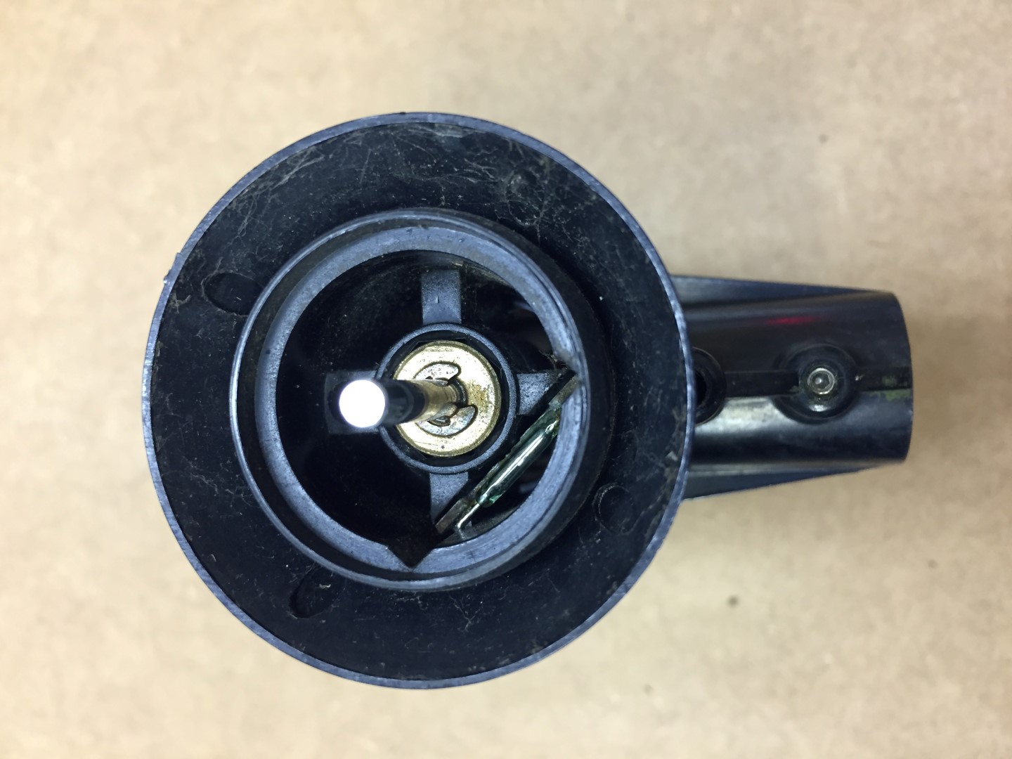
Removing the wind cups reveals the reed switch which can only be accessed by removing the pot.
Step 3
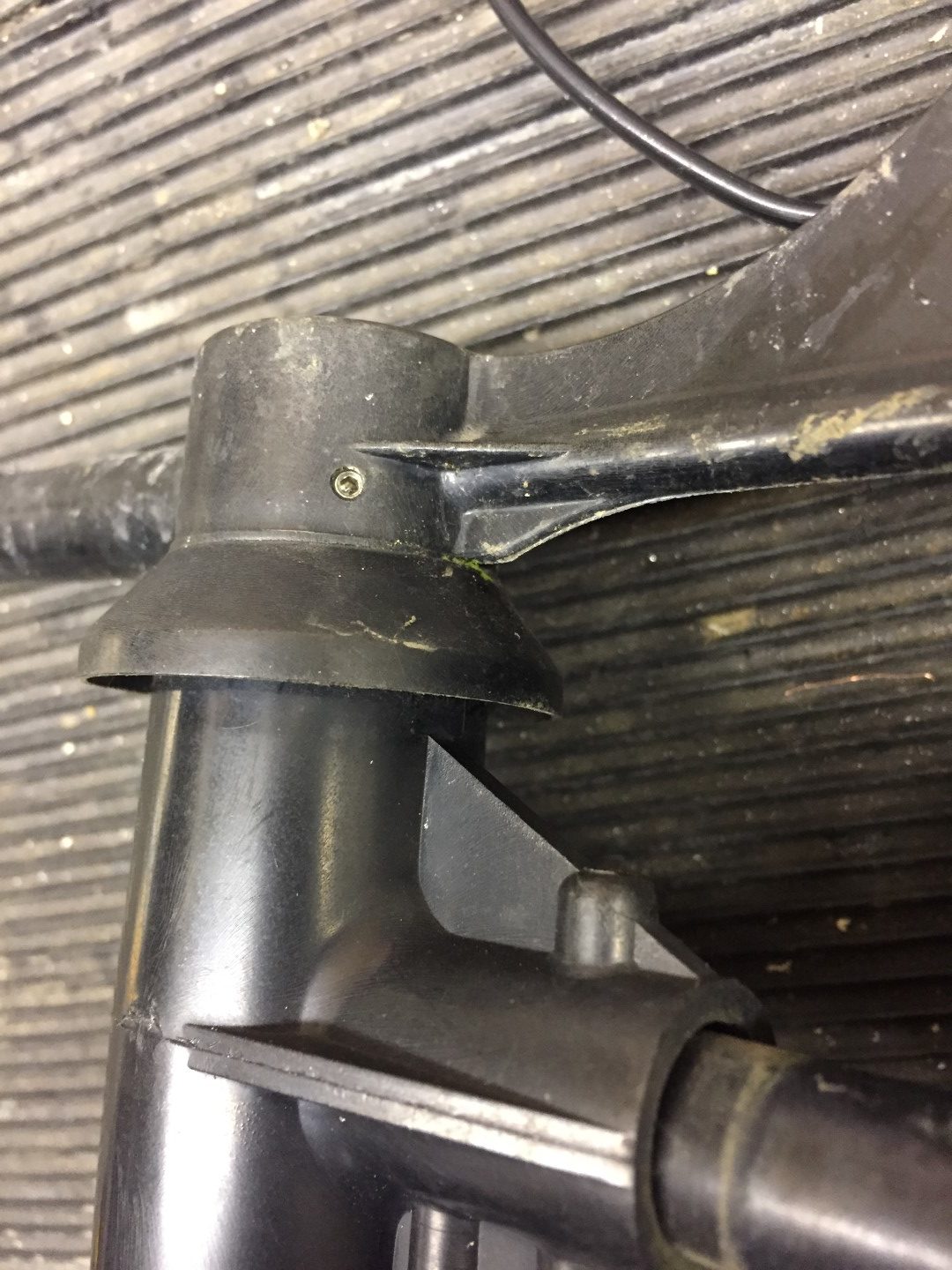
Breaking down the arm and releasing the cable, this is important when we come to remove the pot.
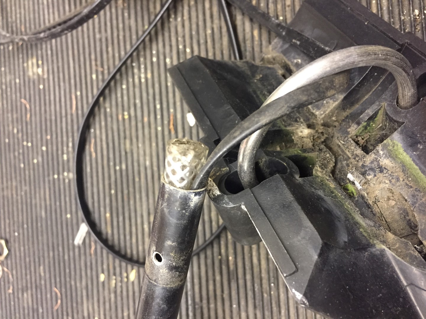
Undo the machine screw and slide this out, once the cable has been released from the in-built grips of the mounting bracket, the tube should slide out of the housing.
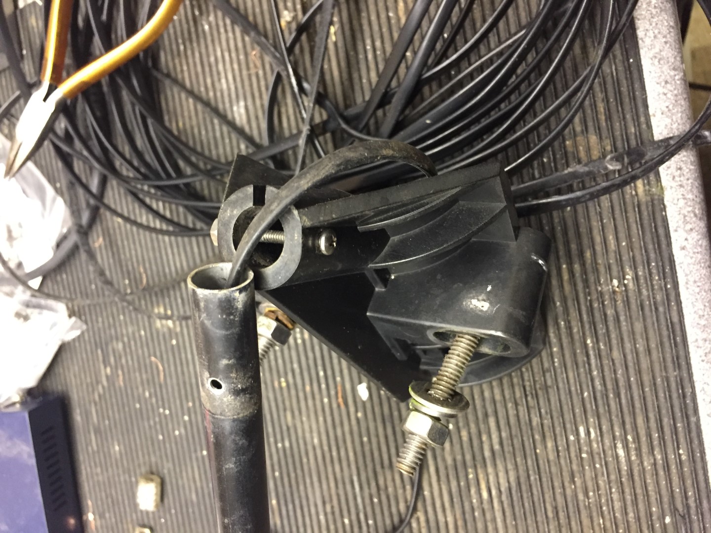
The cable inside the tube has a crude cable grip made from an off-cut of plastic hose, either use pliers or a wood screw in the center of the hose, and gently tease it out.
The next part is to slacken the two allen screws which hold the wind and direction body to the arm, once done, slide the arm down the cable to give you working room.

Step 4
Removing the pot, this is a push fit and held in place by hot melted indents, these need to be cut away with a sharp knife.
Once the indents have been cut away, the pot will pull out of the housing, NOTE – this is a tight fit, use pliers to hold onto the pot shaft and draw towards you, Warning – I pulled too hard and pulled wires off the pot as their is not much slack in the wires from the reed switch, it’s not the end of the earth if you do though as I cut them off anyway!
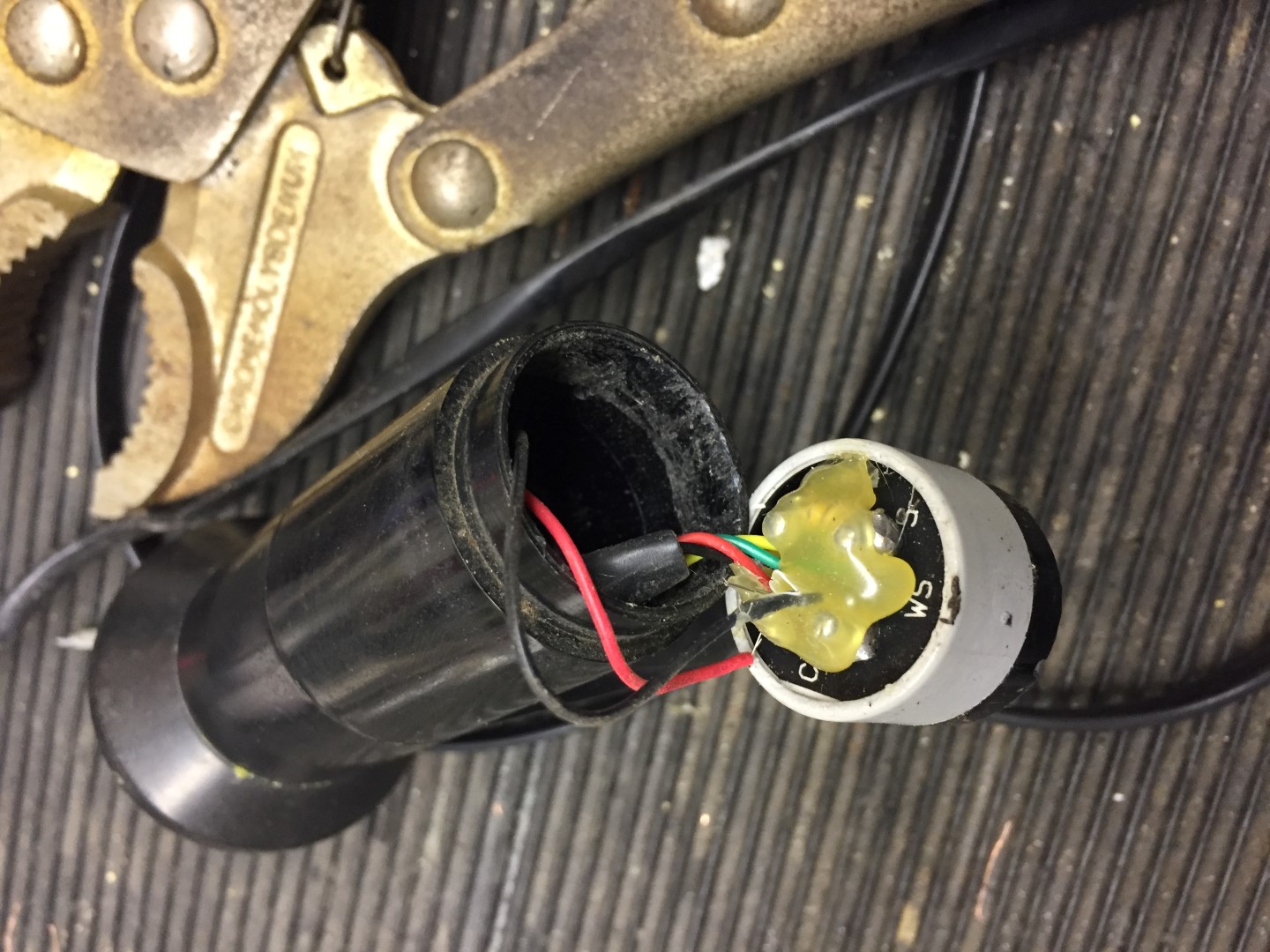
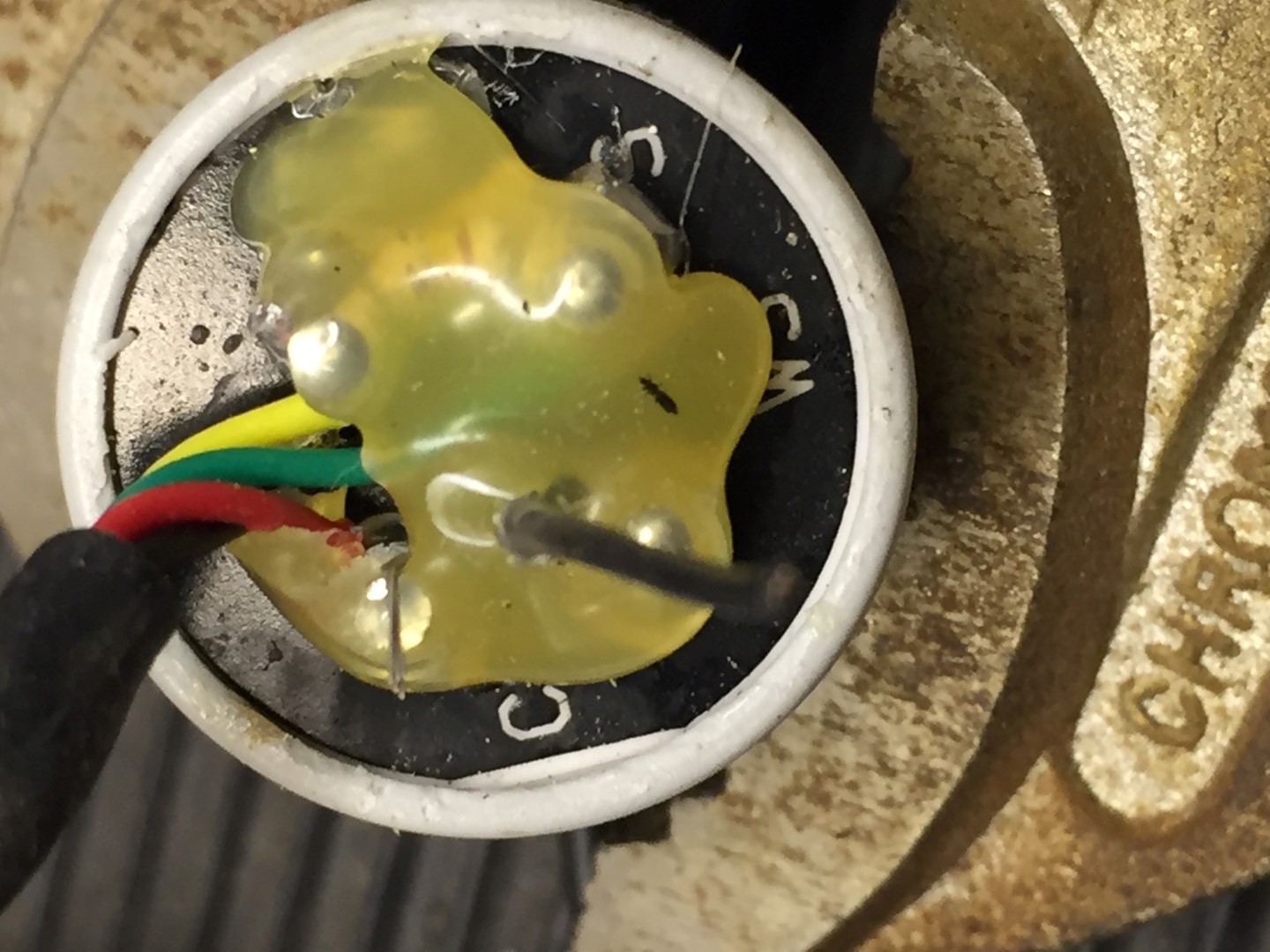
Step 5
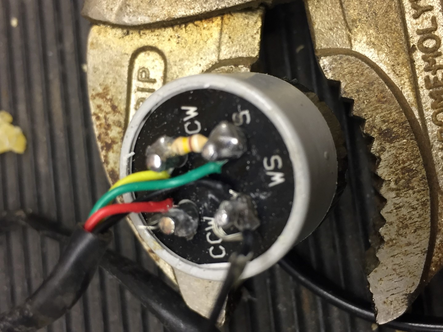
Remove the gunge from the rear of the pot and note which colour wires go where, the red and black fly lead go to the reed switch and these I cut, I also cut all wires to the pot and removed this so I could easily work on the reed switch and bearings.
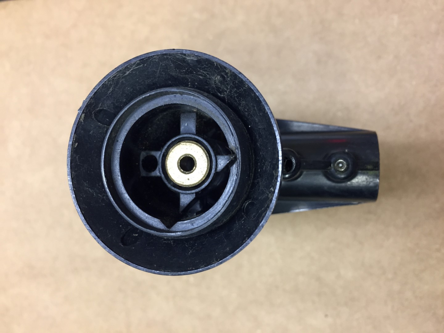
Step 6
The reed switch is held in place with the same gunge (hot glue?) as is on the rear of the pot, due to aging it had gone brittle, using a terminal screwdriver it was possible to break this up from inside the housing body.
Once glue is removed, the reed switch assemble will slide out.
Step 7
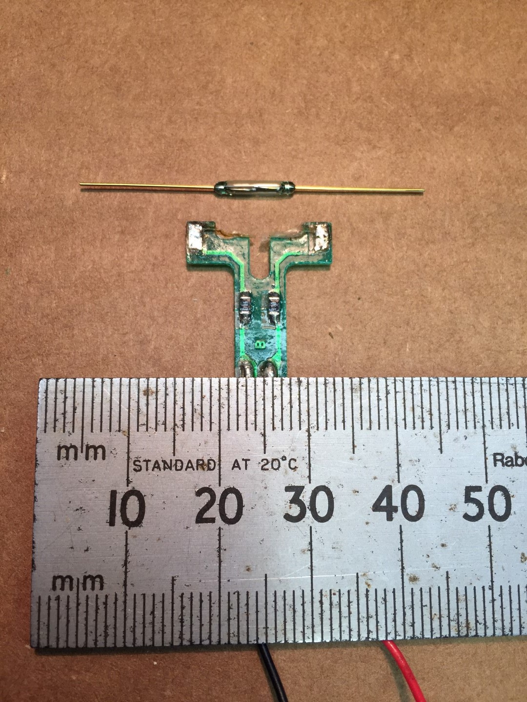
Reed switch replacement, the reed didn’t appear to be visually damaged, only slight rusting. Testing with a meter and magnet, the reed flexed but no electrical contact was made, checks on the circuit board tracks and resistors were OK.
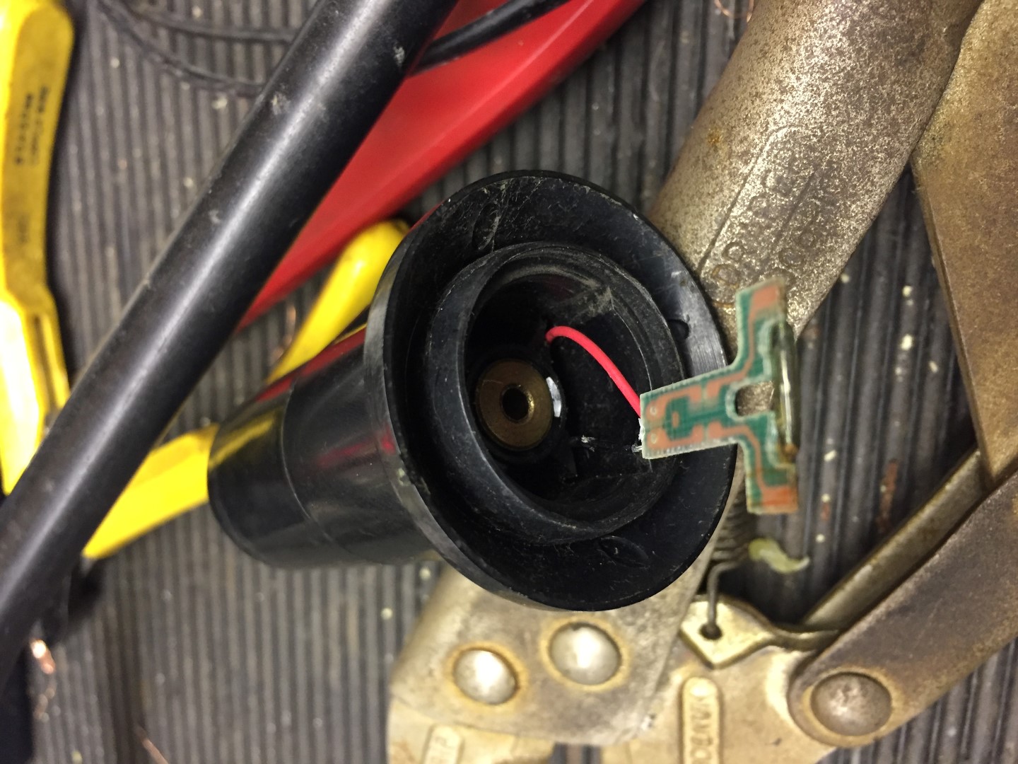
The zoomed pictures make things look easier to handle than they are, the picture below offers some scale.
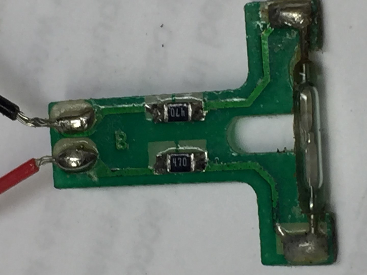
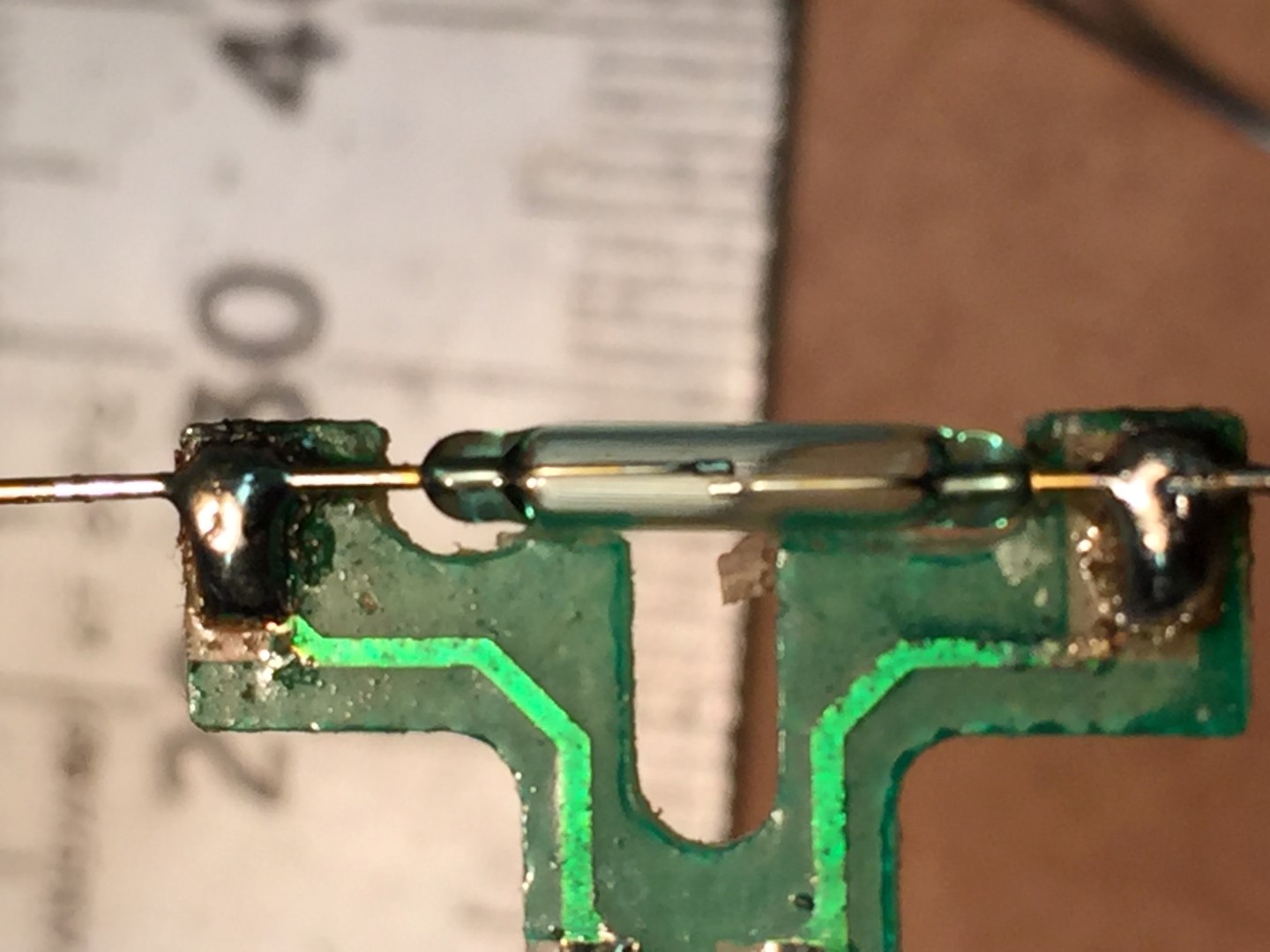
New reed soldered into position with the contact leafs horizontal to the orientation of the PCB, I also replaced the Red and Black wires from the PCB with more flexible ones.
Once the reed switch excess wire was trimmed, sliding the PCB into the housing body and getting it flush broke the reed.
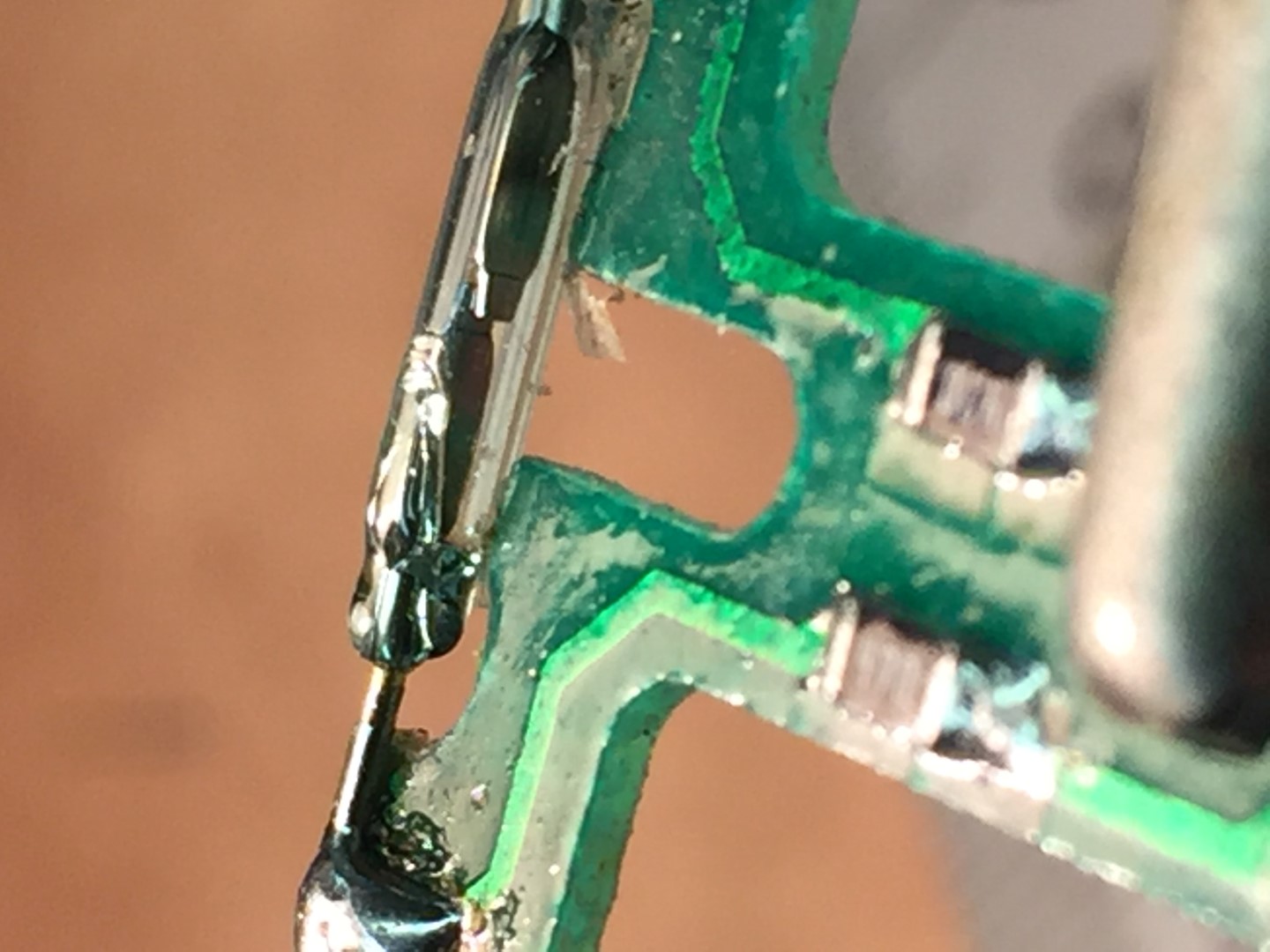
The cause was the reed needs sit,as flat as possible,inline with the PCB, I had used too much solder and this lifted the reed wires slightly off the PCB.
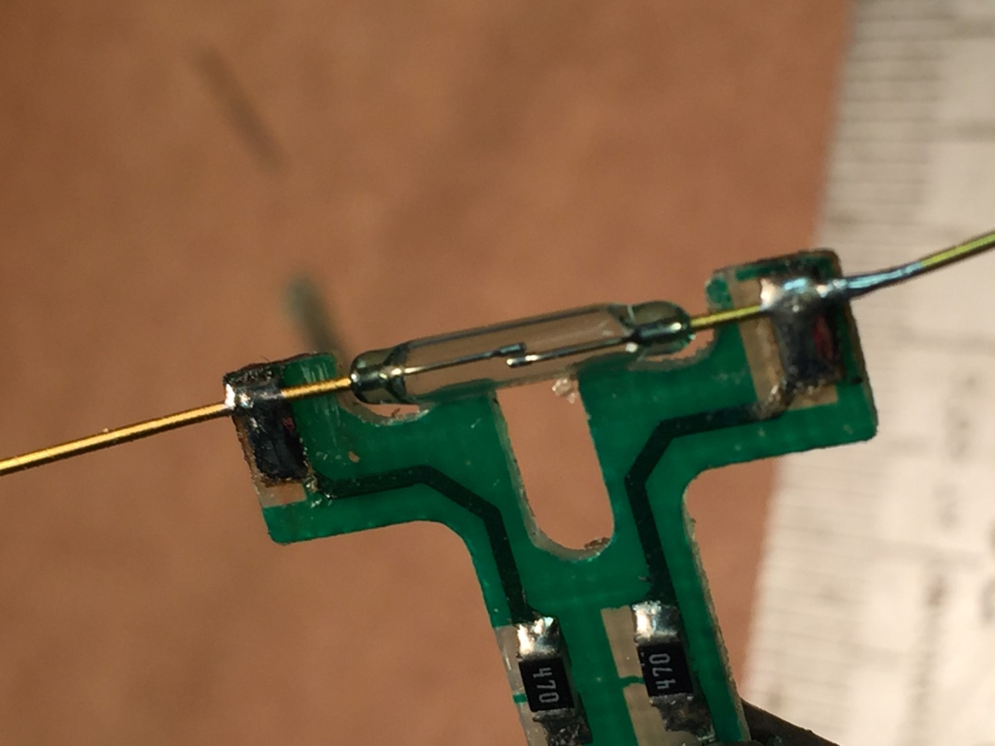
The picture below is the second attempt where I used minimal solder on the PCB pads and pressed the reed wires onto the pad before using a small amount of solder to connect to the pad. This seems to have worked and allows the PCB to slide into the housing and sit flush once the wires were trimmed.
After sliding the reed switch in the body, I connected a multi-meter on continuity buzzer setting, sliding on the wind cups and spinning them, this should cause the buzzer to sound once on each revolution.
Once correct operation is proved, remove the wind cups and reed switch assembly, I sprayed the reed switch with a protective coating and put them in a safe place until later.
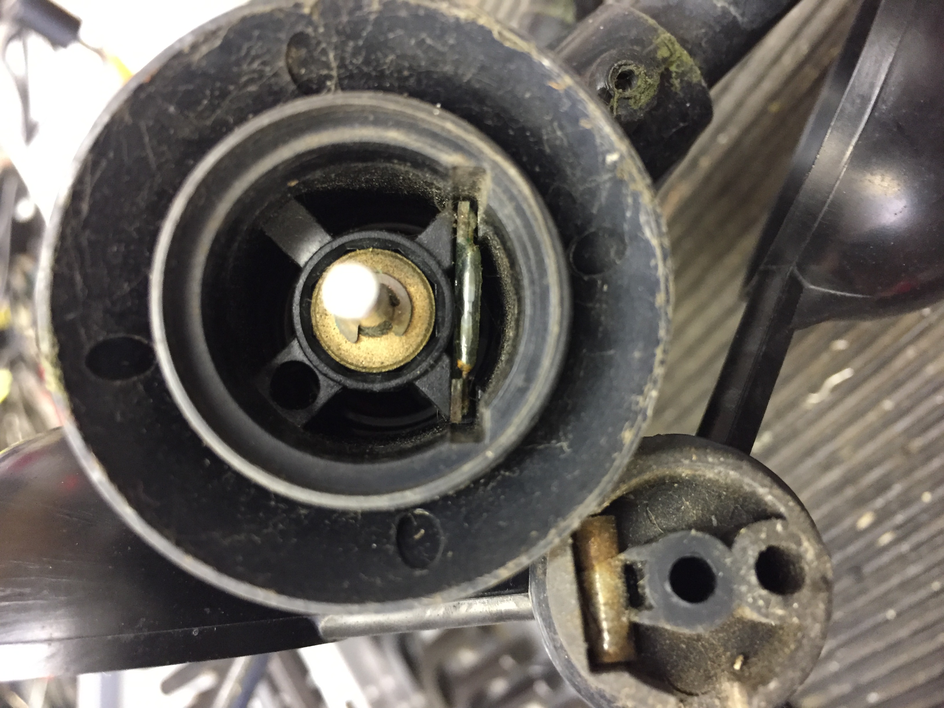
Step 7
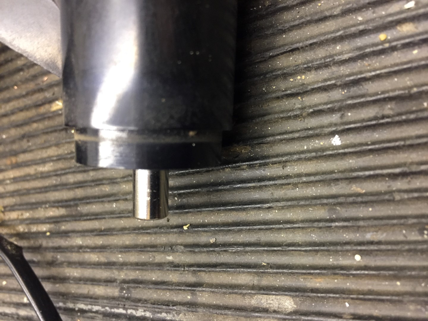
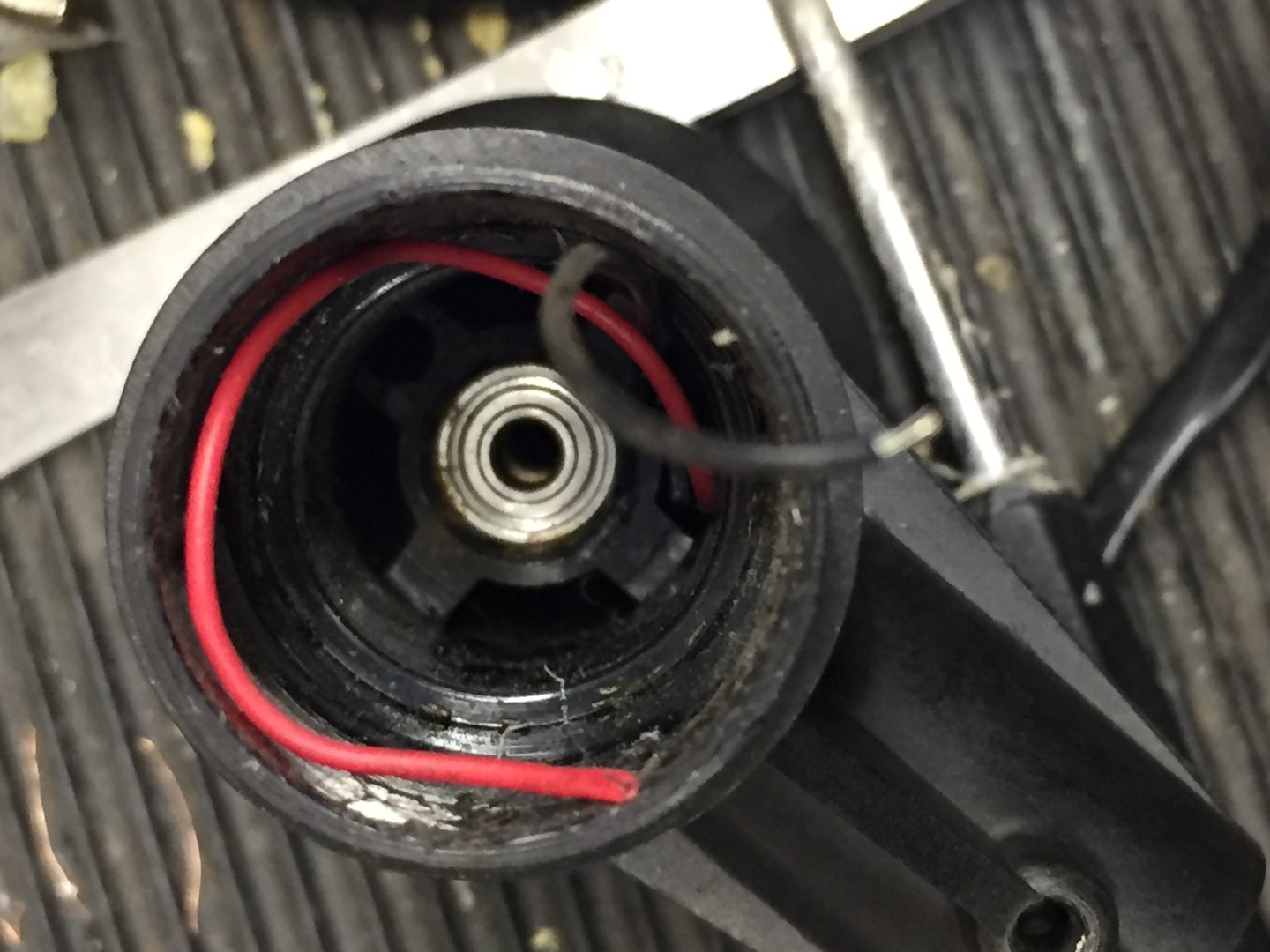
Replace the wind shaft bearing, first the circlip needs removing and retaining for later use, once the clip is off, the shaft can be pushed into the housing.
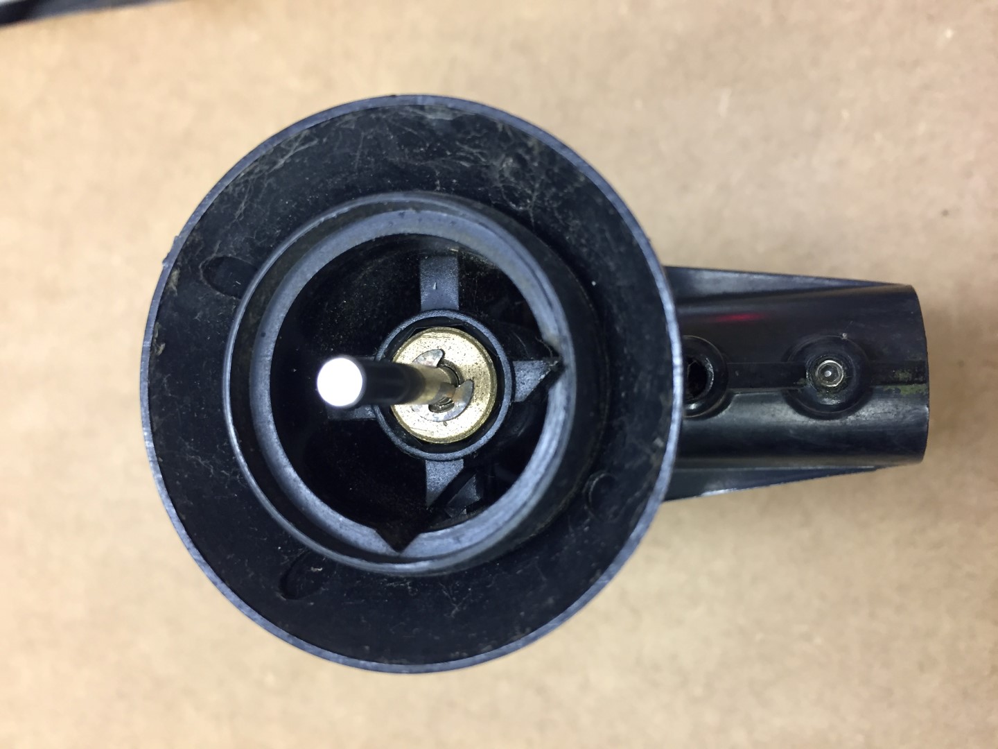
The shaft and black cap can now be removed.
My model has the brass follower looking from the cup side, other pictures I’ve seen show this to be the bearing with the brass follower inside the body, I reassembled in the same order as I took apart.
To remove the bearing, I left the brass follower in and used a terminal driver to go through the hole and using it at a slight angle, gently tap against the underside of the bearing, moving around the inside of the bearing and tapping to tease the bearing out of the housing.
The old bearing is in the bag and it is in good condition with only slight signs of rusting.
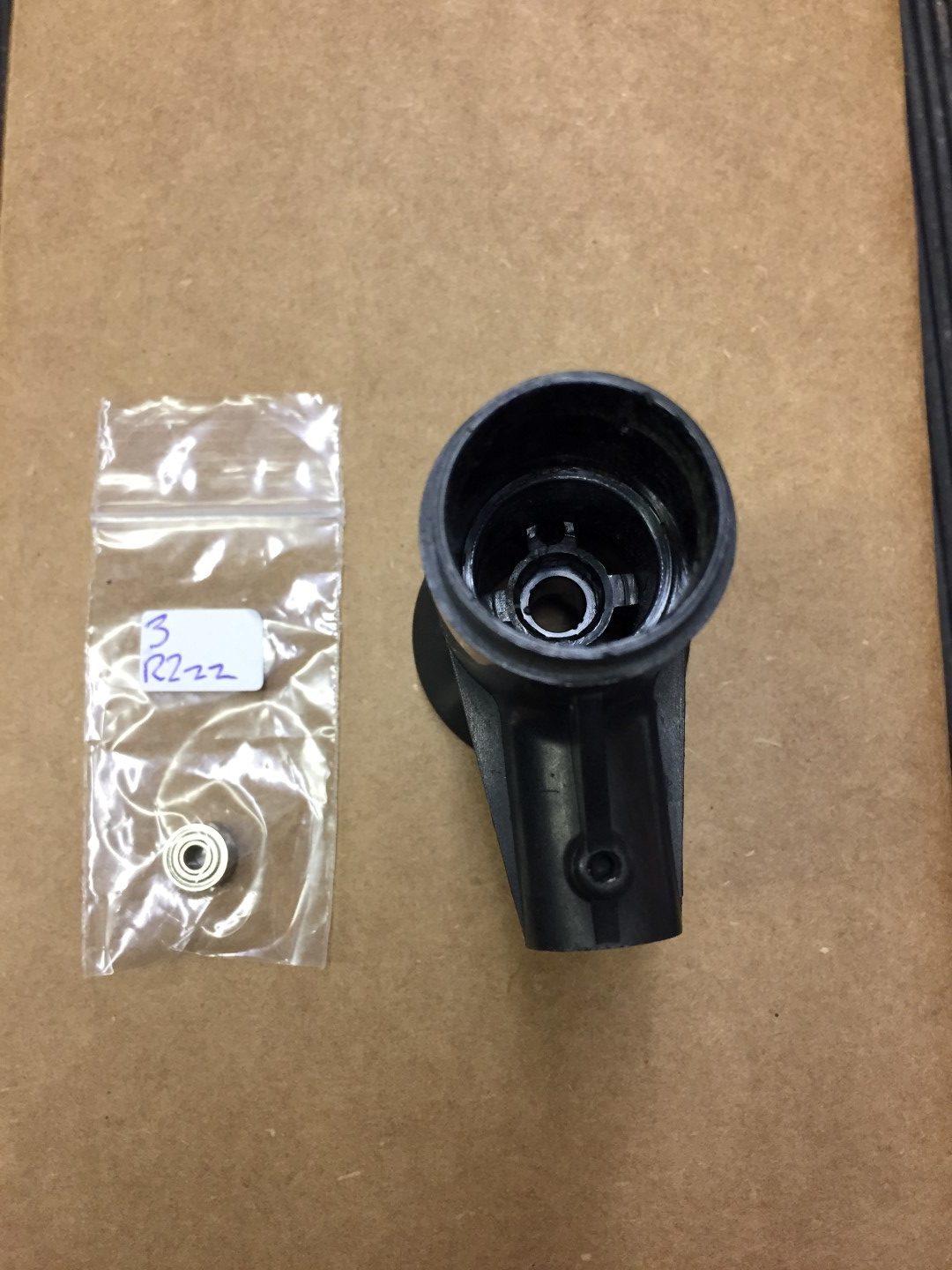
The new bearing simple pushed into the housing.
Step 8
Reassembly:
- Slide shaft into place and fit circlip, make sure the shaft spins freely, I applied a light oil to the brass follower only.
- Slide the reed switch into place and making sure that it sits flush, after putting the bearing protective cap on and I then used hot melt glue from inside the housing to secure everything in place.
- Checking that the cable is still threaded through the arm, pass the cable into the housing ready for soldering onto the back of the pot.
- Once with wires are back in place, I sprayed a protective coating on the pot and pushed it back into the housing checking that the marks I made at the start are aligned.
- I didn’t melt fix the pot, the protective costing will act as an adhesive.
- The arm was then re-affixed and secured.
- The arm cable grip was pushed back in, check that the fixing hole is clear for the machine screw when pushing the grip back in.
- Fix vane back on to pot, aligning grub screw with marking on shaft.
- Fix wind cups onto shaft.
Testing
I used a Glaxio Telecom Wall Box RJ11 which cost £2.69 from eBay as a breakout box for testing that the reed and directing pot are working:
My old 6410 is now refurbished and will be stored in the loft until the one in use packs up.
If you need any further information, please contact me.