Updated 29 September 2023
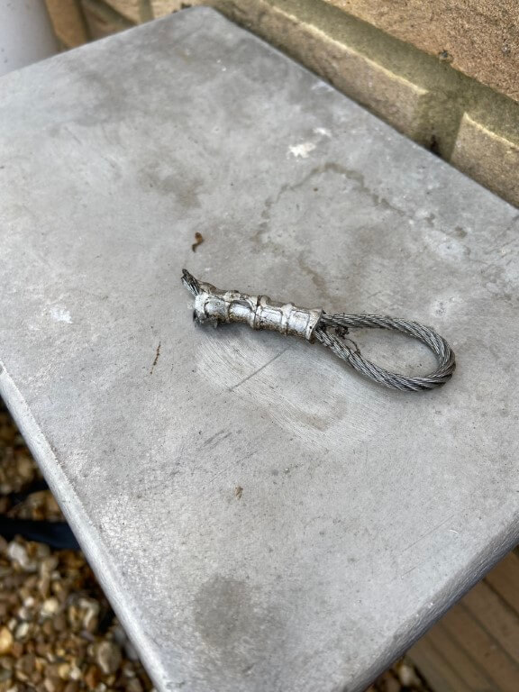
I had a senior moment when I tried to raise my electrically operated mast with the locking pin in, result that I snapped the wire rope !!
Well, what a nightmare and it was all of my doing.
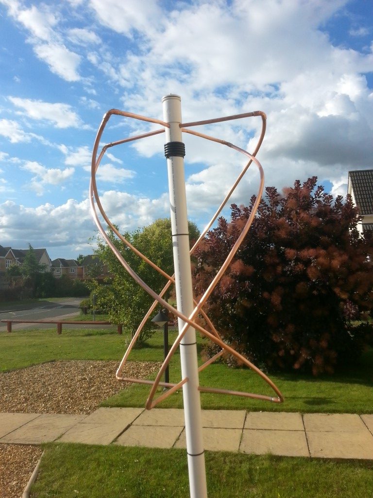
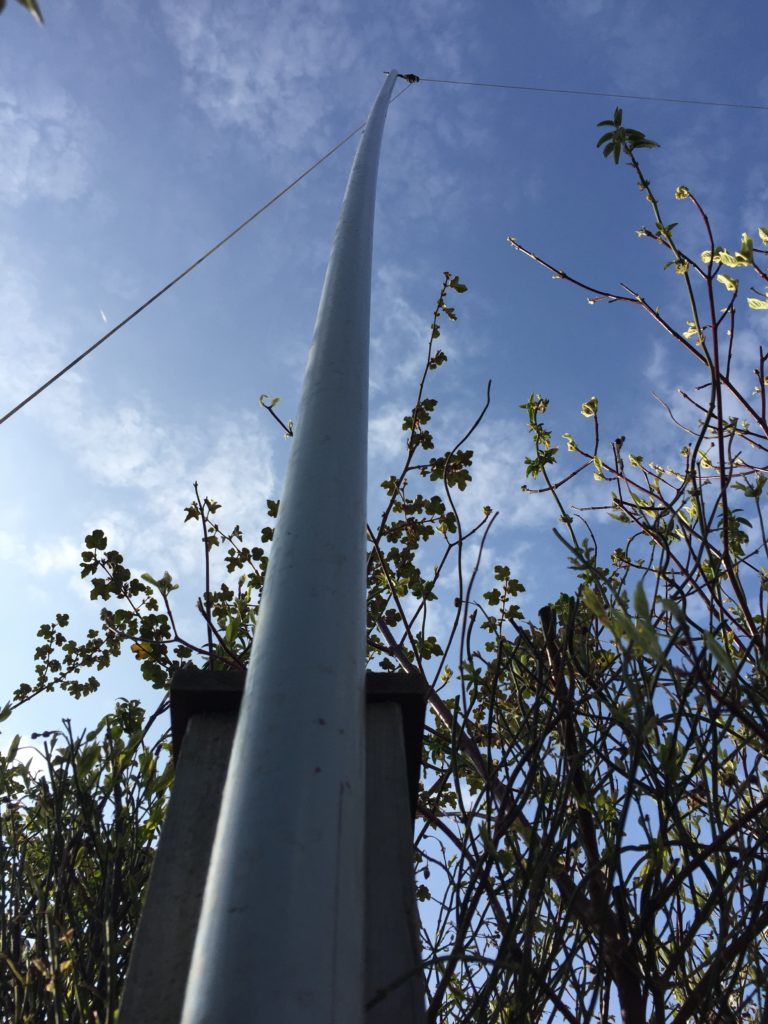
The design of my mast is that it has a single electrically operated winch cable which can either lift the inner section of the mast, or luff the mast down for maintenance.
I had built a logic control for the winch, but didn’t engineer in being stupid, so when I decided to lift the mast after a number of years of not touching it, operating the momentary UP (raise) switch didn’t do anything, and not thinking I put the control into safety override mode to use the remote control winch hand control, pressing the ‘UP’ button, the winch motor started but sounded strained, which I put down to stiction of the mast, then ‘PING’ the cable snapped, it was at this point i realised that the inner mast pin was in place stopping it lifting.
So the predicament I have found myself in was that the mast can neither be raised or luffed down for repair, the only solution was the jack the mast up in-situ and replace the cable, not an easy task.
Equipment
The existing wire rope was 4mm diameter, so I took this as an opportunity to install 5mm, I bought 20m but used 19m, this was from GSProducts and cost including a wire clamp was £24.77.
The wire rope needed ferrules to crimp the end where it fits inside the inner box steel mast, so I needed these and a crimping tool, both of these were from The Wire Rope Shop costing £86.20.
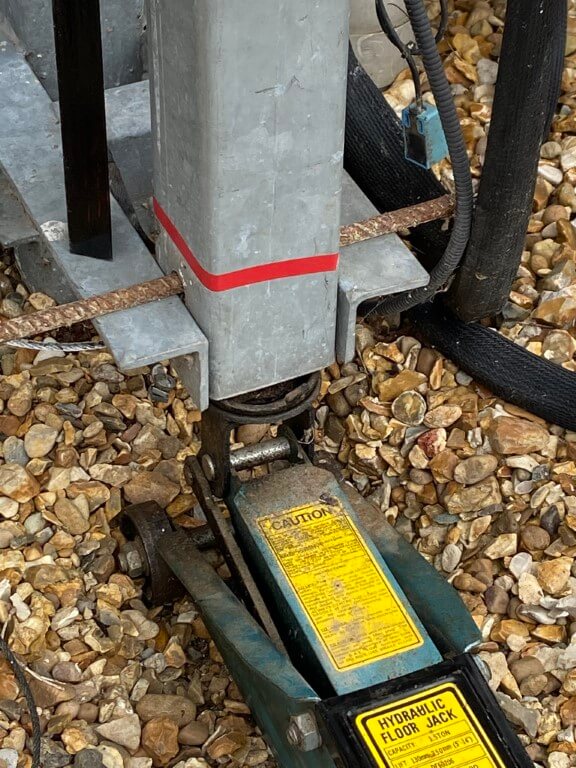
The mast weights approximately 150Kg and will need lifting just under 600mm, I bought a Farm Jack from Amazon which cost £79.99.
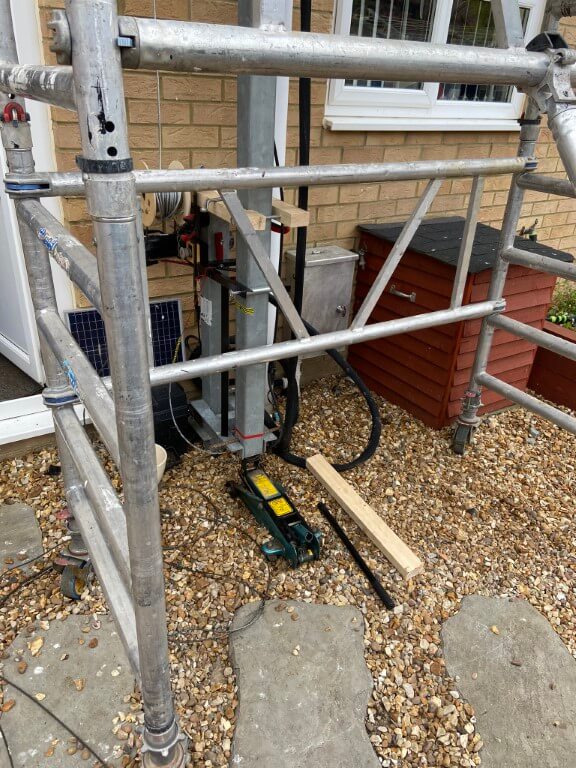
Finally I needed a tower scaffold, I used a MiTower Plus from HSS (code 81216) costing £129.56 including delivery/collection for 7 day hire.
Not a cheap mistake!
How
First job was to fabricate a metal support which the mast was lifted on to:
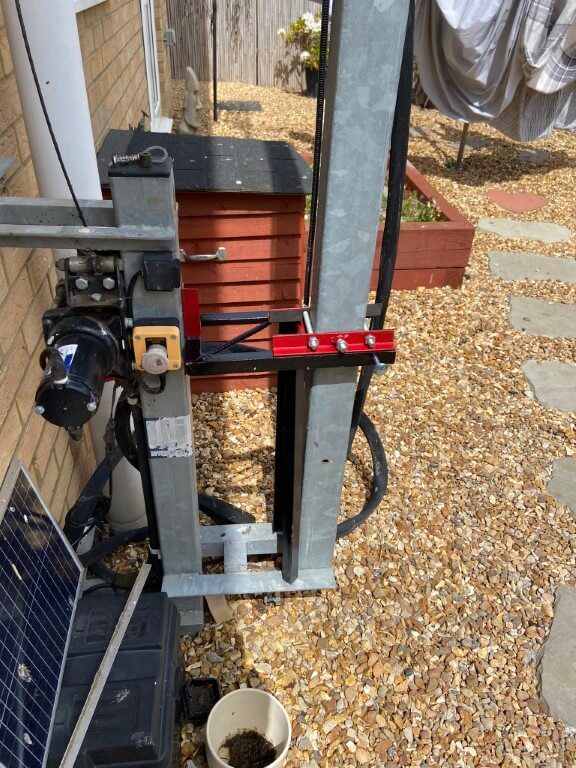
The idea behind this was that the masts pivot bolt would be removed enabling the whole mast to be lifted so that the hole in the mast which you can see in the picture, will be jacked above the black frame, where the red bracket will be clamped to the outer mast, and then lowered gently onto the frame to support the weight.
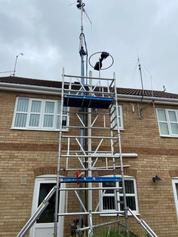
The scaffold went up easily enough to enable me to comfortably work on the mast, access was important as I needed the thread a replacement wire rope inside the mast, I also had to unbolt the top mast cage from the inner section steelwork, enabling the inner box section can be accessible at the bottom of the mast.
Using a car jack the masts pivot pin was removed and with a piece of steel rebar through the pivot hole, the mast rested until the next stage.
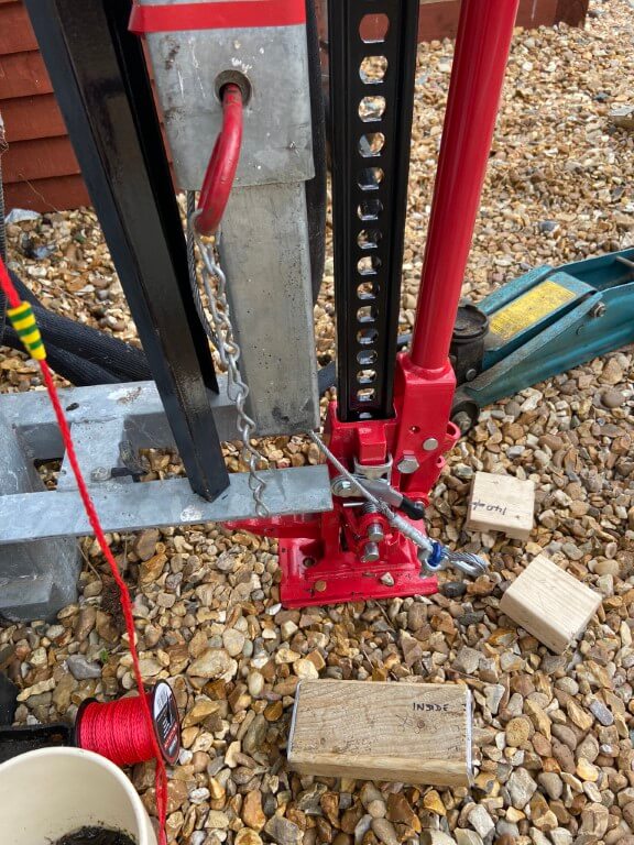
Using the Farm Jack to take the weight, the mast inched up to a height where a 260mm wooden block could be put inside the mast.
The mast was clamped and the Farm Jack was lowered, this was a mistake, the Jack simply slammed to the floor, fortunately the clamp held the masts weight and the block was inserted and we used a car jack for the rest of the lifting and lowering process but returned to the Farm Jack to lower for the main mast drop.
For future reference, the Farm Jack needs a downward force acting on it in order to lower in a controlled way, as we had removed the weight of the mast from the jack by clamping it, the Jack dropped.
With the mast supported, it was time for the next stage and that was to remove the bottom bolt from the mast top cage and begin the process of getting the cage box fixing to lower inside the mast.
This process was a bit tricky as it involved controlled lifting and lowing until all the bolts were removed and the cage assembly was sitting neatly inside the mast, unfortunately the inner mast was stuck inside the cage box.
A few lifts and rapid drops of the inner caused it to finally drop onto wooden blocks and we could get on with the repair.
This picture shows the new steel wire rope with two crimped ferrules and a eye bolt, the rope is around a galvanized thimble, this was later modified to fit as in its current form, it was too big to go inside the 60mm x 60mm inner box section.
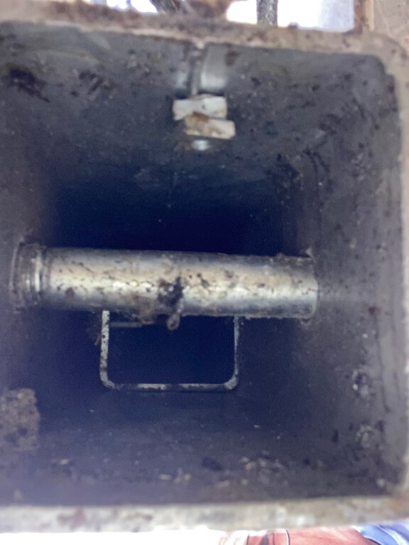
For clarity, the wire rope comes down the inside of the mast where it enters the inner mast through a hole 50mm up from the bottom of the mast, spacing of the inner section from the outer section is maintained by two sets of bolts further up the mast.
Reassembly
This was the most stressful part!
The inner mast section needed to be raised so that it sits inside the cage box, but no matter what we tried, the inner box could not be centralised and no way could the rotator assembly be manually lifted due to the weight and the fact that I would have needed a higher working platform.
My solution was to drill holes in the outer mast walls where the inner mast naturally was leaning, the holes were 9mm and I tapped them to accept grease nipples, hence they will server a purpose afterwards.
Once the holes were drilled, I used a couple of screwdrivers to manipulate the inner mast and on the second attempt, the inner slide perfectly into the cage, much to my relief as I didn’t have a plan ‘B’.
Finishing Off
All bolts back in and mast greased, I decided to replace the two mast limit switches and check the wiring, good job I did as one for the sensor wires had eroded through due to moisture ingress.
Glad its all back together and working now, but it was a lot of work and money for a lapse in concentration 🙁
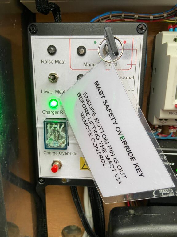
Control Modification
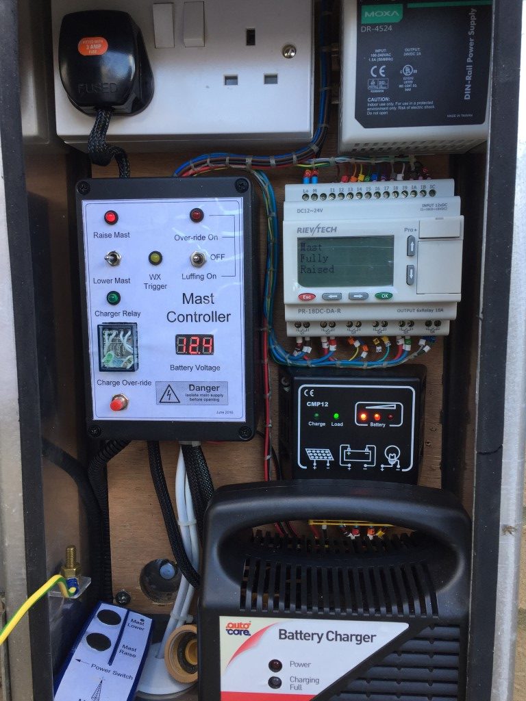
In an attempt to stop and make me think, I’ve modified the control unit to include a key-switch with a warning notice attached to remind me not to be a dick!
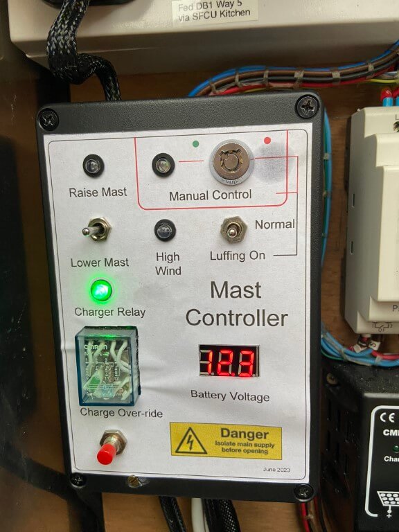
Mast controller now has a key-switch and warning RED flashing LED which illuminates if the control is set to either Luffing or Manual Control, the latter will only be enabled if the key is turned to the red dot.
Hopefully these measures will work 🙂
Update
I added overcurrent detection to the winch motor as a belt and braces approach to avoid repeating my original mistake causing the winch rope to break when set to manual control.
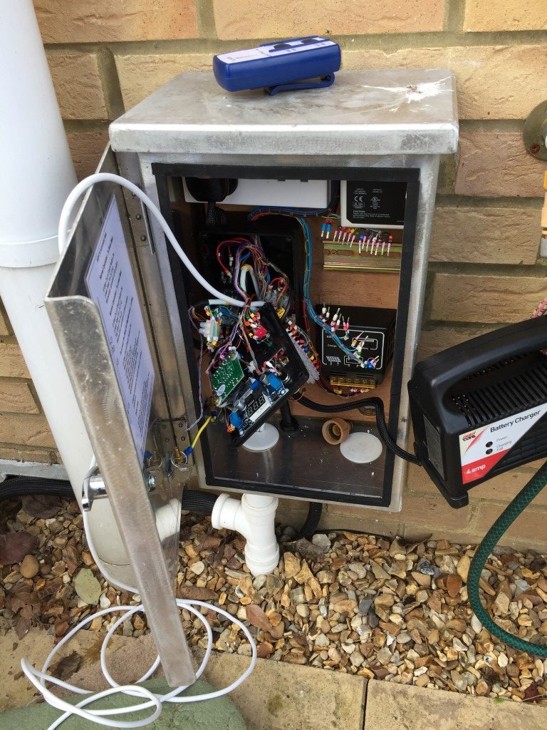
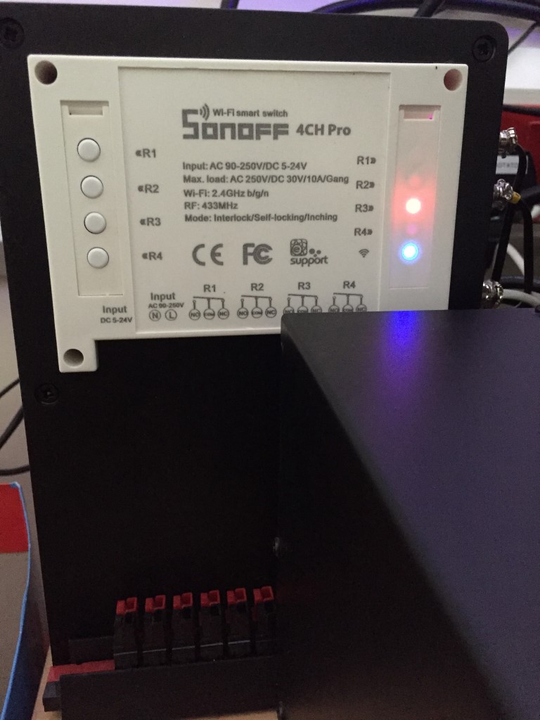
My system uses a 12v car battery as the power source to the winch relay control and motor which is located in a battery box local to the mast.
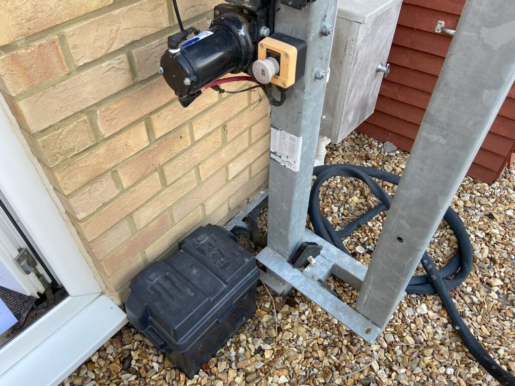
A 24v signal is sent to a relay in the battery box from the main controller and this in turn enables 12v to be sent to the motor controller for manual or wireless control, the project was to add a second layer to the relays control circuit.
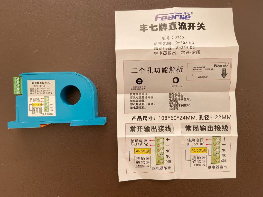
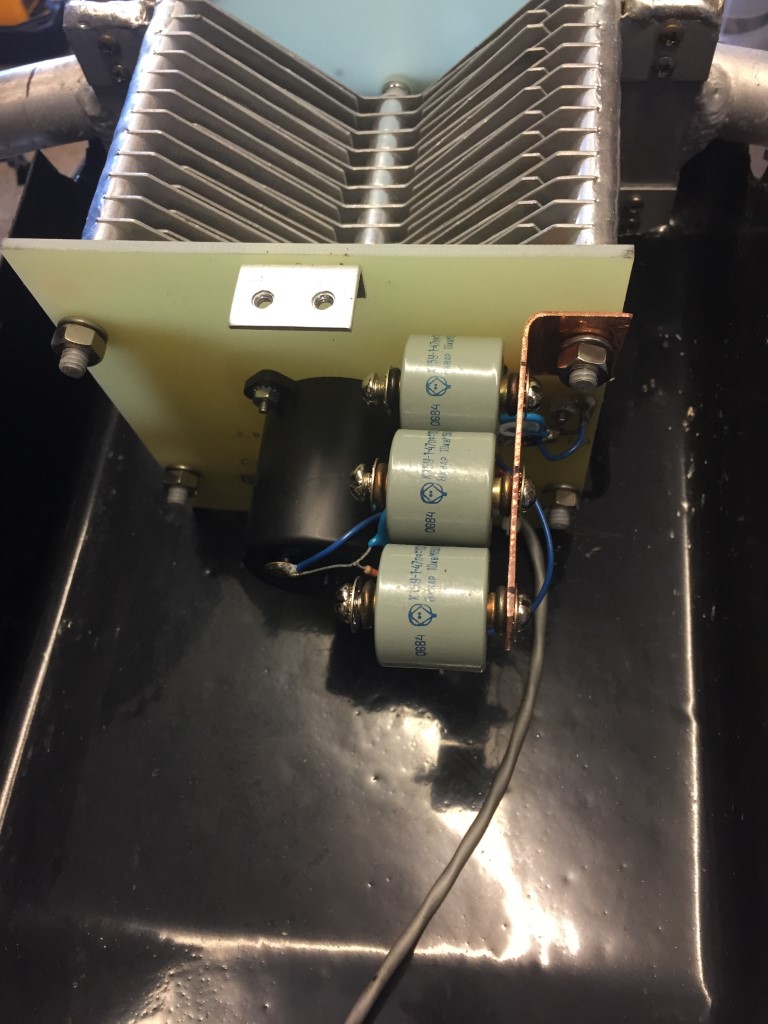
Using a clamp on ammeter I already knew the motors current draw when winching up, so I bought a 0-50A current relay from Aliexpress for £12.00.
With power applied and the battery positive cable passing through the current relay, I trimmed the potentiometer on the device so that it is just set below the tripping threshold.
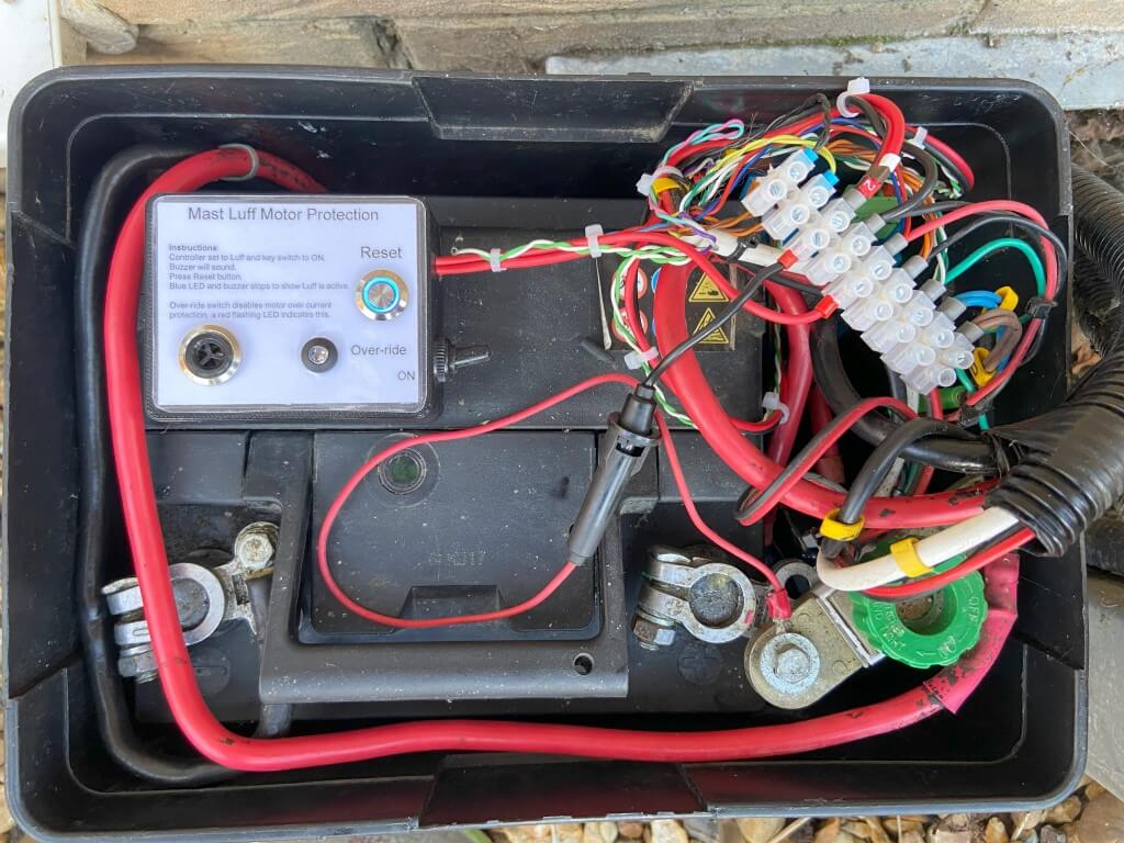
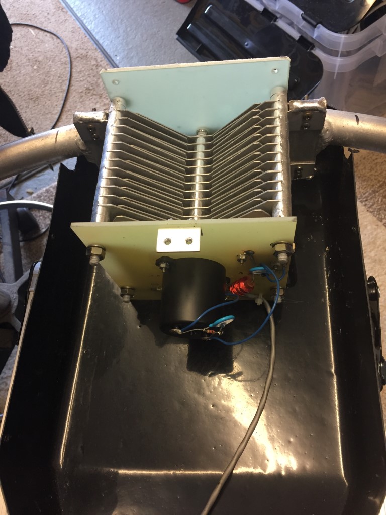
Bit of a messy picture showing the protection device in place with the blue led lit around the reset button indicating that the luffing relay is energised and the mast motor control is ready.
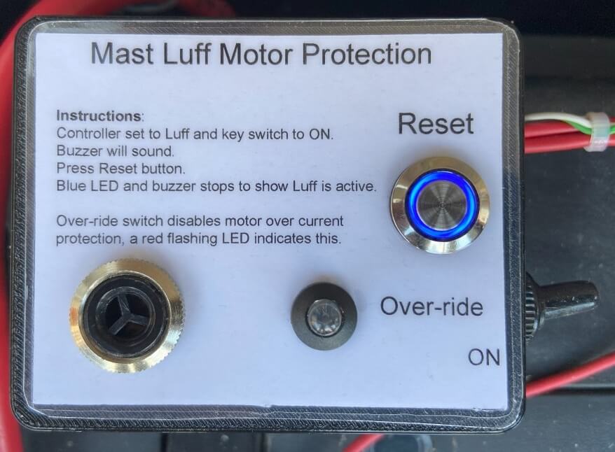
The circuit of the protection is straightforward, when the controller is set to Luff, a 24v signal is sent to a relay, the positive goes through the Normally Closed contacts on the current relay onto the Normally Open relay contacts of the motor controllers supply, therefore this relay will not latch until the relay contacts are shorted, in this case with the reset button.
When latched, the blue led will light and 12v applied to the motor controller, should any of the following listed things happen, the relay will drop out and remove power from the motor controller, stopping the motor until manually reset:
- Luff signal removed by controller
- Overcurrent relay contact open on detection of excessive current draw
In order to remind me to reset the protection relay when set to Luff, a buzzer will sound, this activates when the relay is not latched and is supplied by the Luff signal voltage from the main controller.
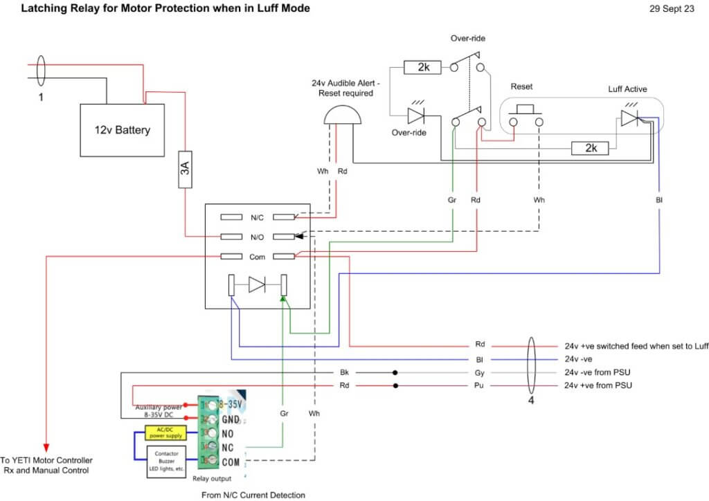
I did include a motor protection over-ride switch and flashing red led to show when it is on, this simple bypasses the current detection relay and will hopefully not be needed.
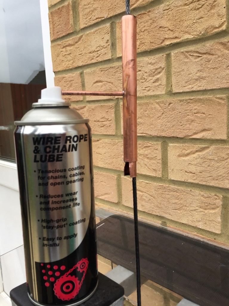
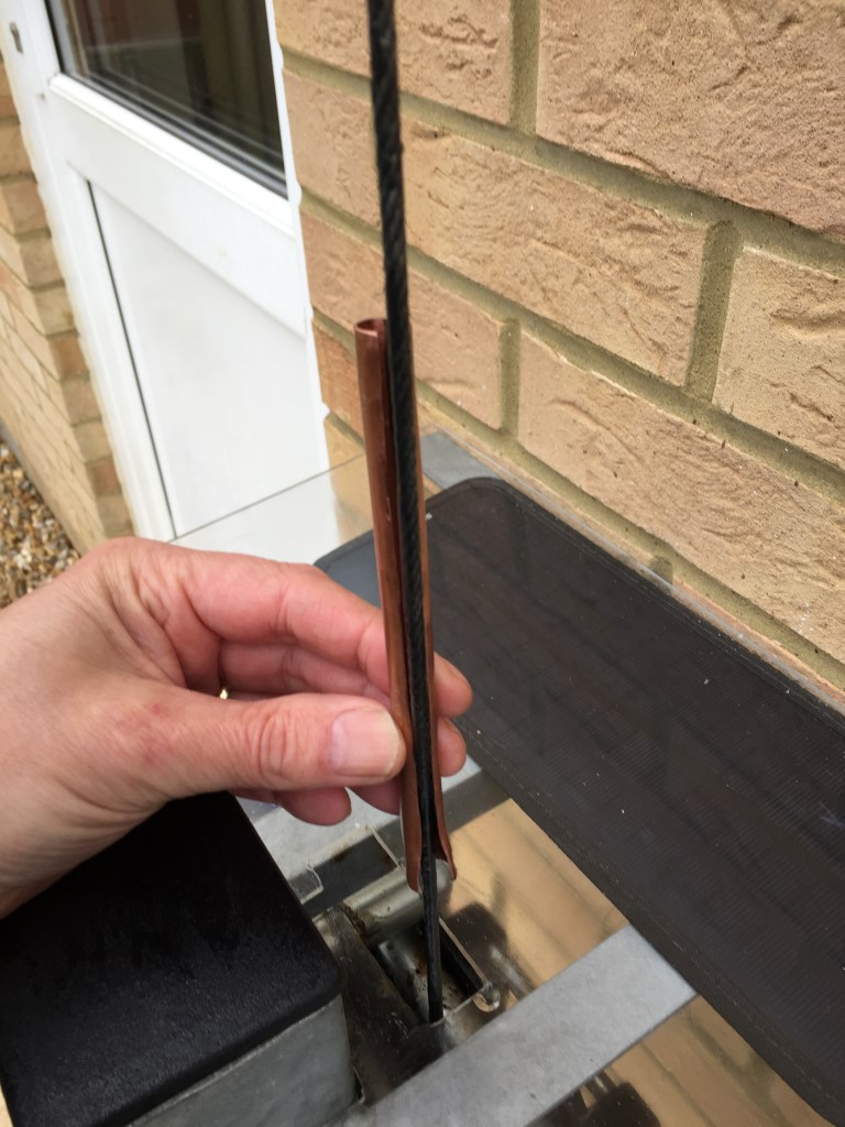
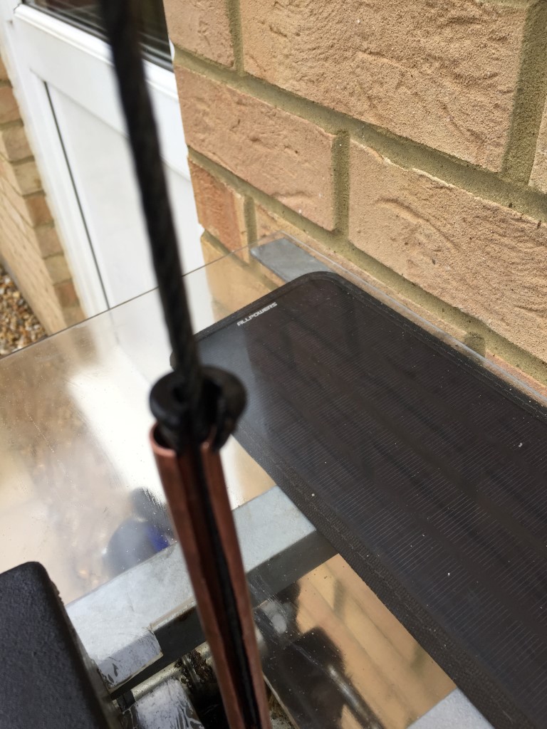
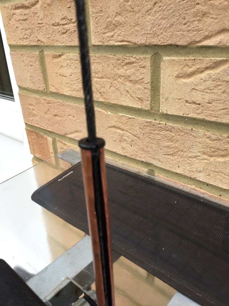
 Noting the alignment, the 10mm pipe is pushed inside the 15mm pipe, the 4mm pipe protuding inside the 15mm pipe ensures the 10mm pipe can only fully slide in if the slot aligns, The lip on the 15mm pipe holds the grommet in place:
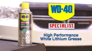
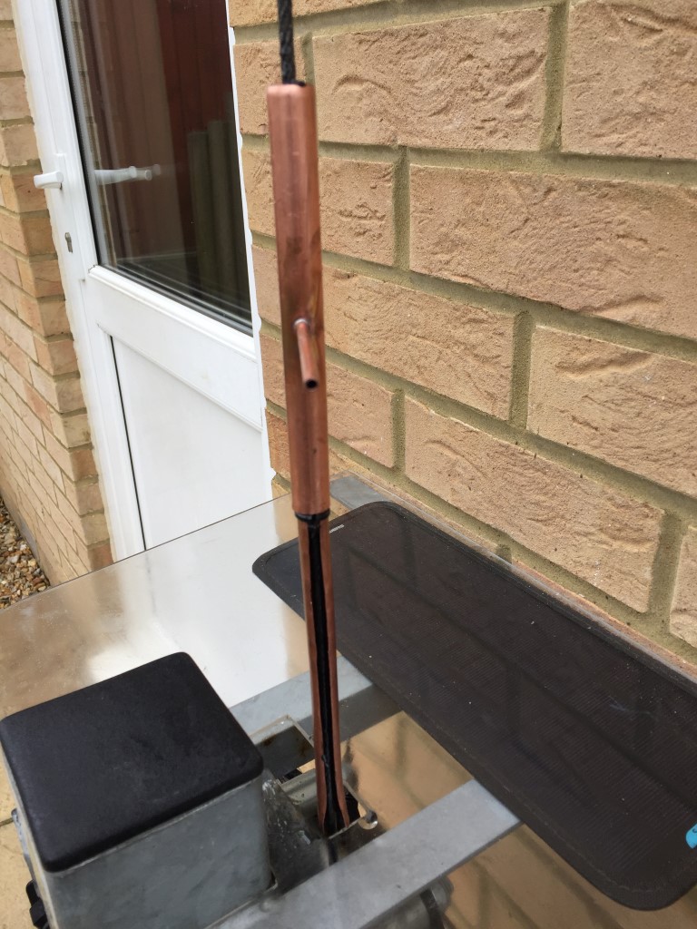
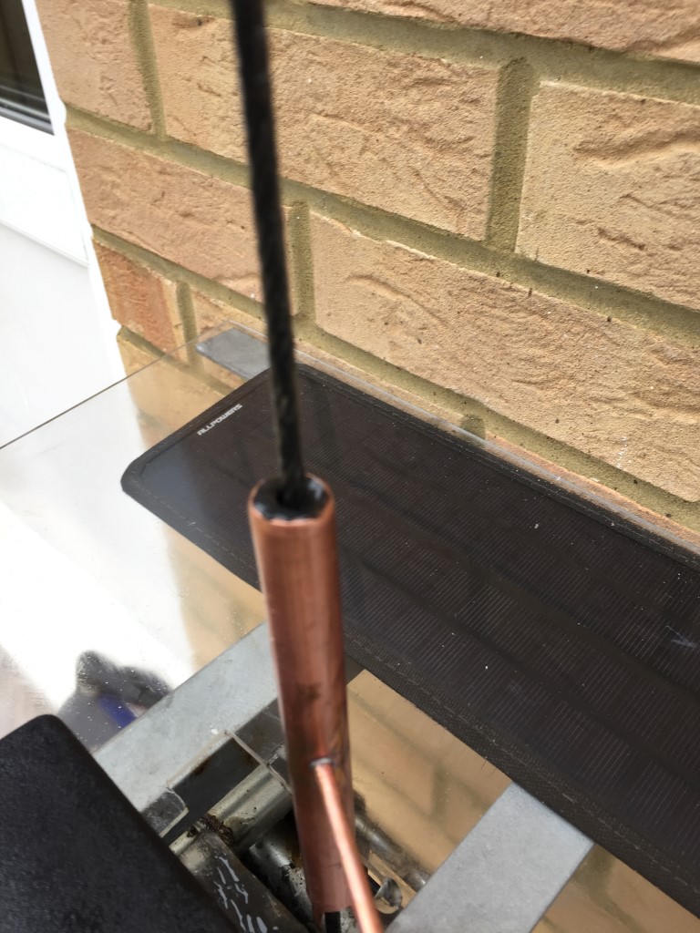 The finished product works quite well and gives an even coating to the wire rope, the length of the 4mm pipe was to allow the spray can to rest on a bracket, so I simply raise the mast and hold the spray button down 🙂