Category Archives: Ham Radio

SG-237 Tuner Control pt1

Updated 4 April 2022

As I want a relatively discrete antenna arrangement for my radio ham interest, I have opted for a single random length wire with automatic tuning being dealt with by a SG-237 tuner, Part 2 of this blog will go into the fixing details of the antenna and hardware.

I have made a tuner control unit out of a single gang blank faceplate, although this is not required for the basic installation, it will give me some control and confirmation indications at the shack end of power and that the tuner has finished tuning.

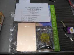
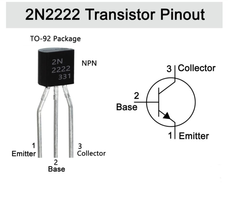
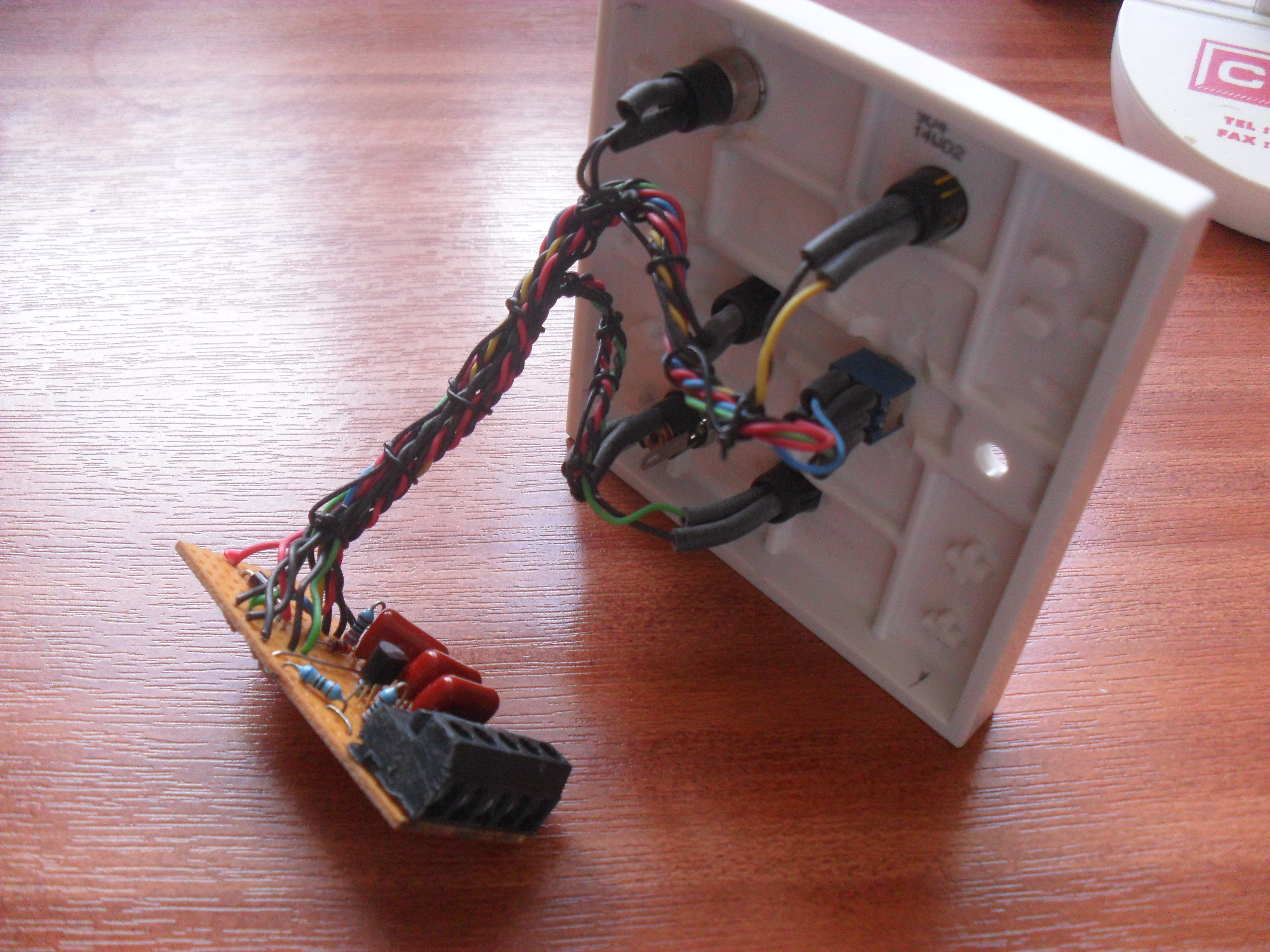
The schematic I followed with the exception of the polarity protection diode and Antenna Available ON led, is within the manual available from SG Tuners, I used an small offcut of veroboard to make the unit and this will be inside a backbox, the faceplate displays the lights and access the controls.

board v2

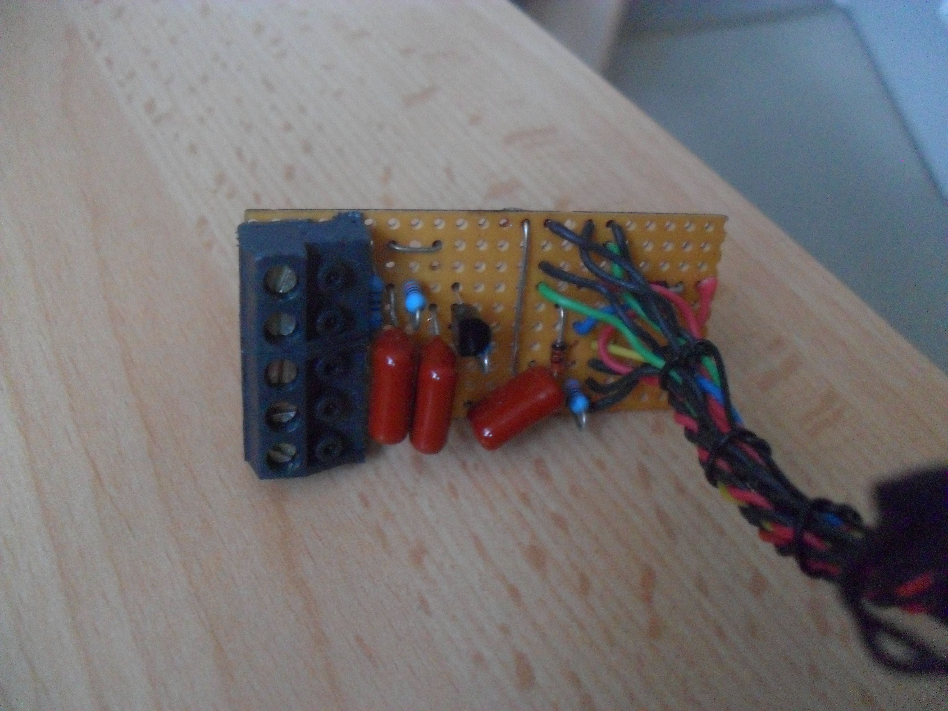
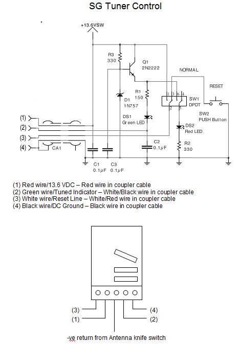
The veroboard layout is shown here.
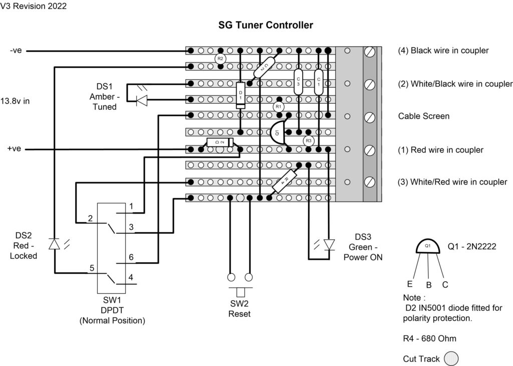
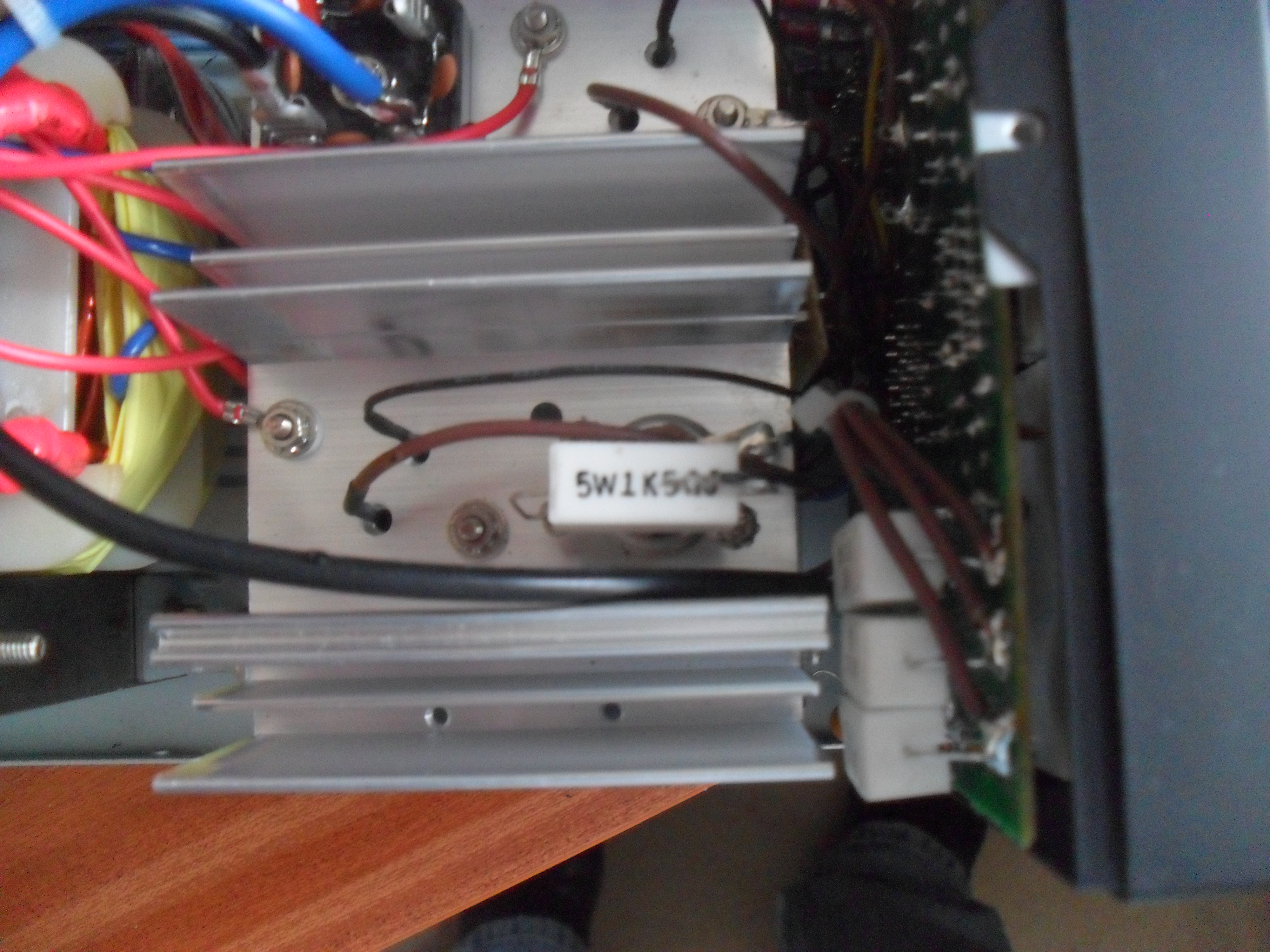
This is the unit fully assembled but not yet labeled, holes were drilled will a hss bit on a slow speed, letting the drillbit do the work with little pressure, I bought off ebay a Dremel copy, and used the grinding bit to gently open the holes to the right size and also to grind down the faceplate support ridges:

Virgin Faceplate
SAM_5040

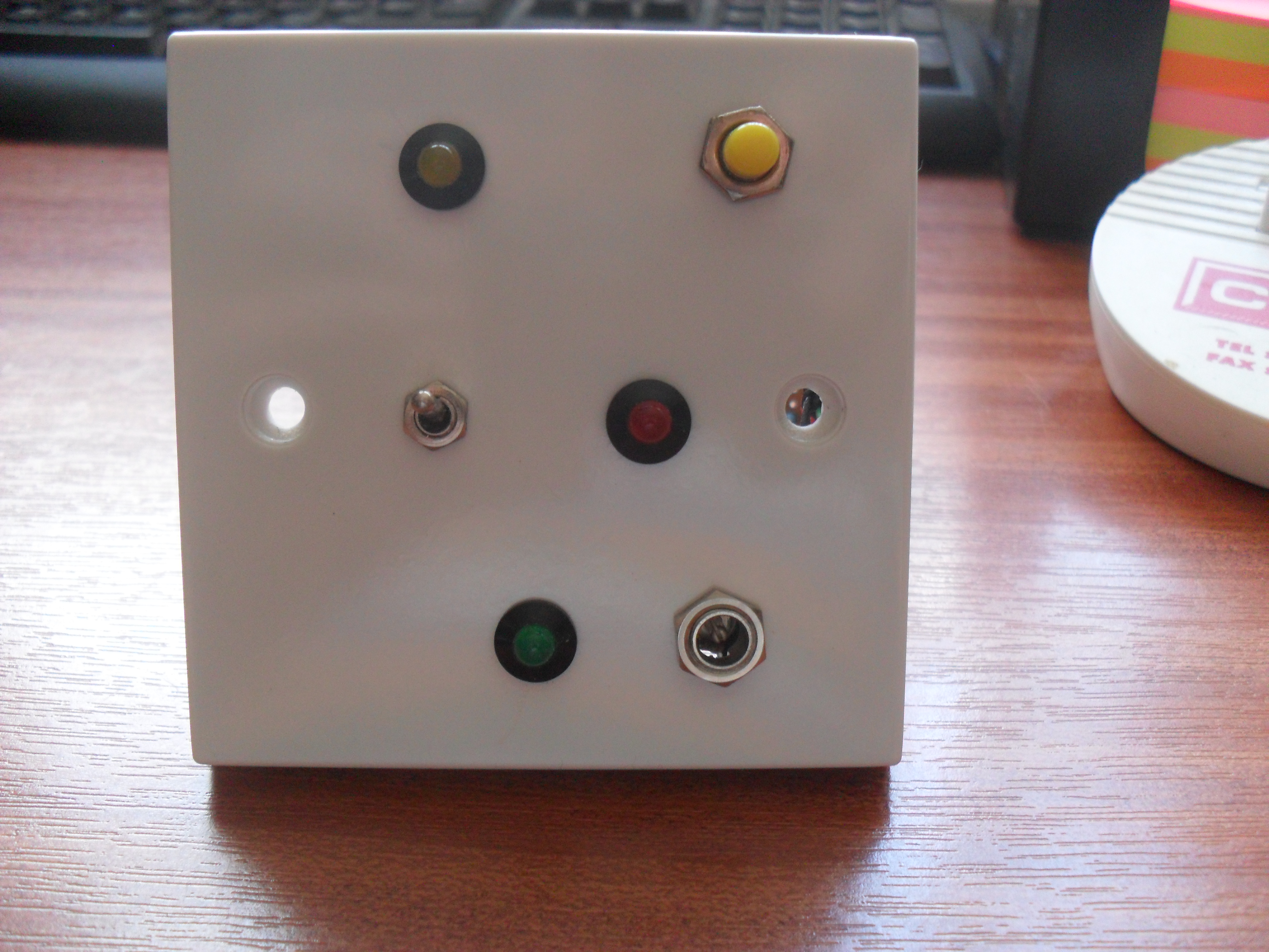
Labeled unit ready for installation, the label is made in Word or Visio to the right dimensions, printed to plain paper and cut slightly oversize, the reverse of the paper then has double sided self-adhesive tape applied, the front of the label then has a clear self adhesive covering applied (the sort of clear covering you would use for school books), I used a sharp knife, steel rule and cutting mat to cut just inside of the second outer boarder of the label, I printed a double border in case I made a hash of cutting it the first time, at least I could have another shot.

Once the label was ready, I striped down the faceplate, lined it up and carefully stuck it to the faceplate, to cut the holes, I held the faceplate to the light and used the knife to starburst the holes before going round the edges to clean up.

faceplate v2

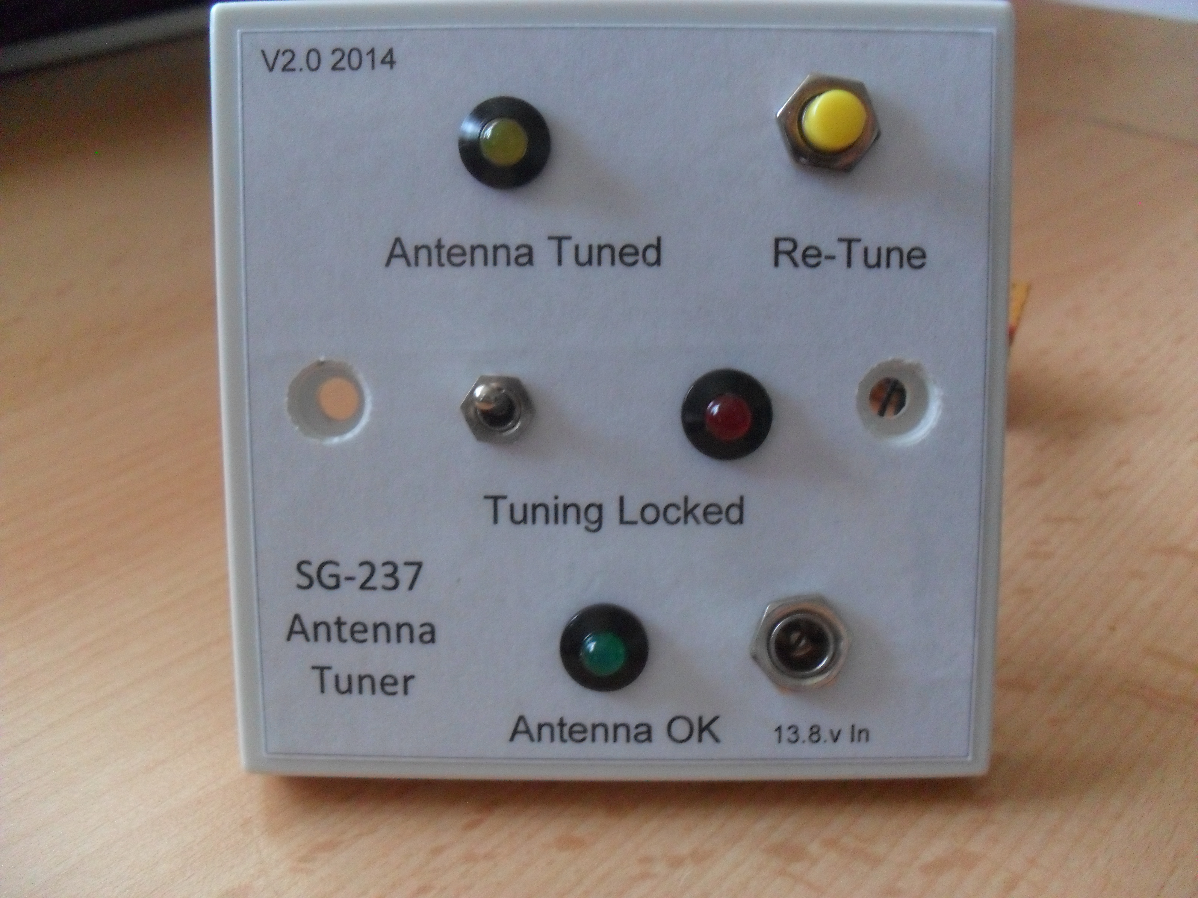
I have added an led which will light when the longwire is NOT to ground, the transfer will be done by a mechanical knife switch, the switch is a double pole double throw, one contact pole will switch the antenna wire from the SG-237 to ground, whilst the other pole will switch the Anntena Available led, credit goes to Bill O’Neil, KW8KW for a simple but effective solution to what could be a costly problem.

INSTALLATION IN SHACK

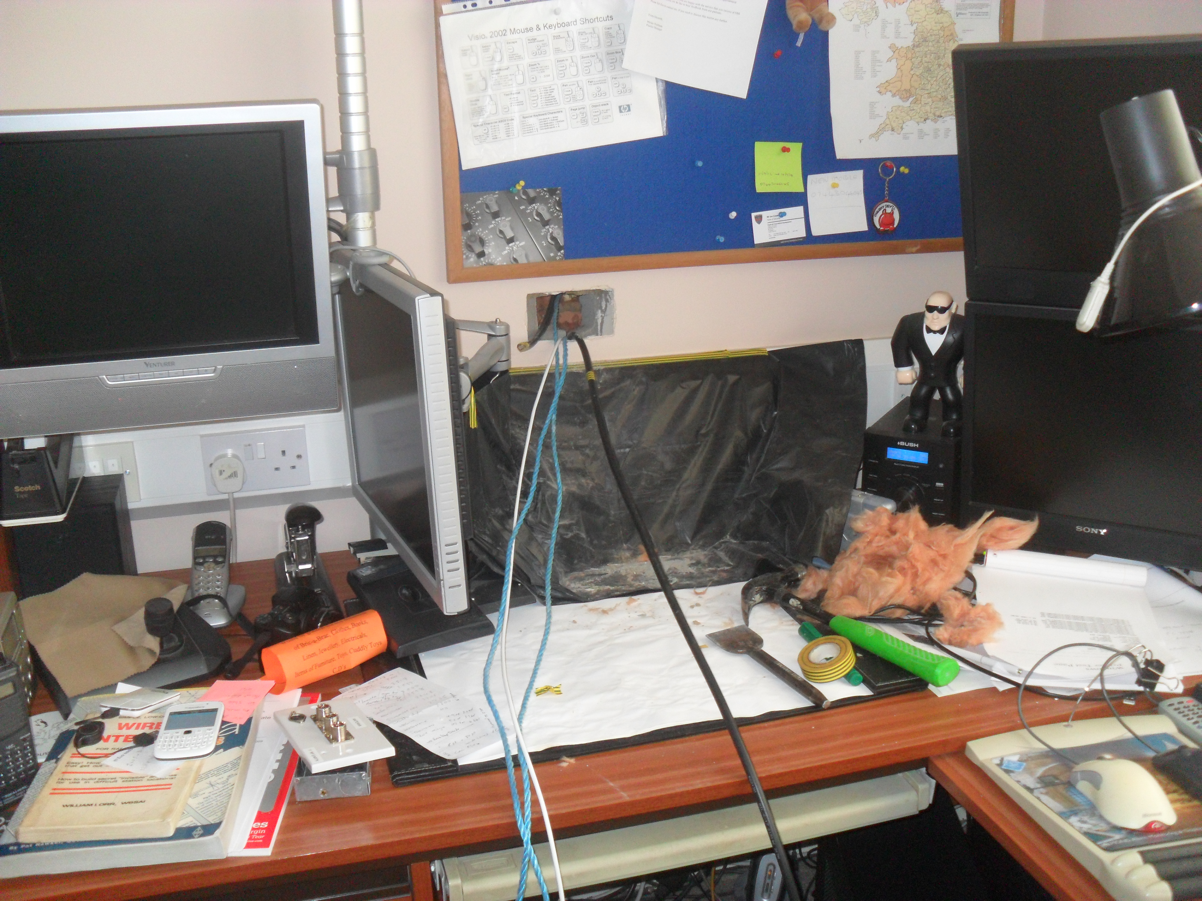
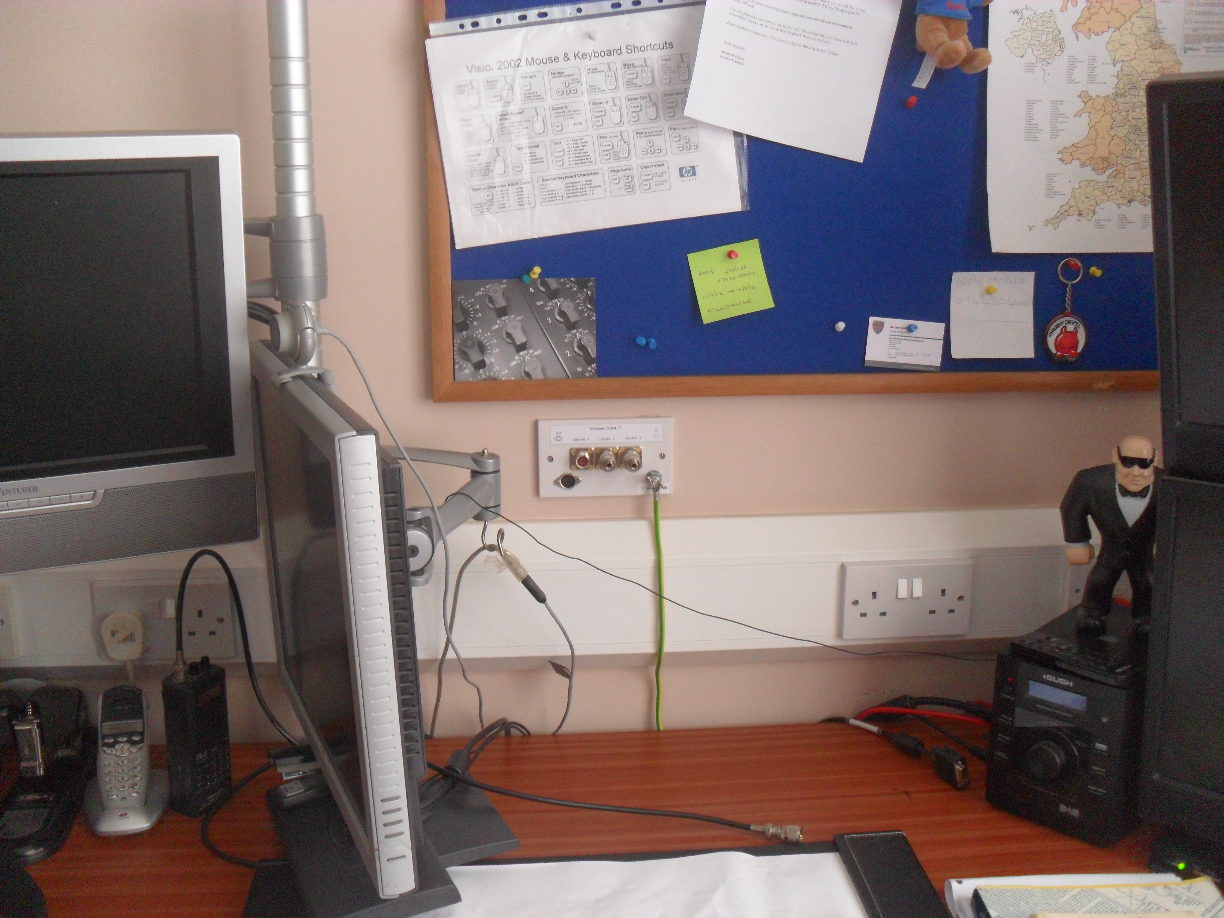
I opted to fit a double dry lining box and to have once side blanked as a spare for future use, the positioning of the tuner control was important as I did not want the display obscured by the PC monitor.

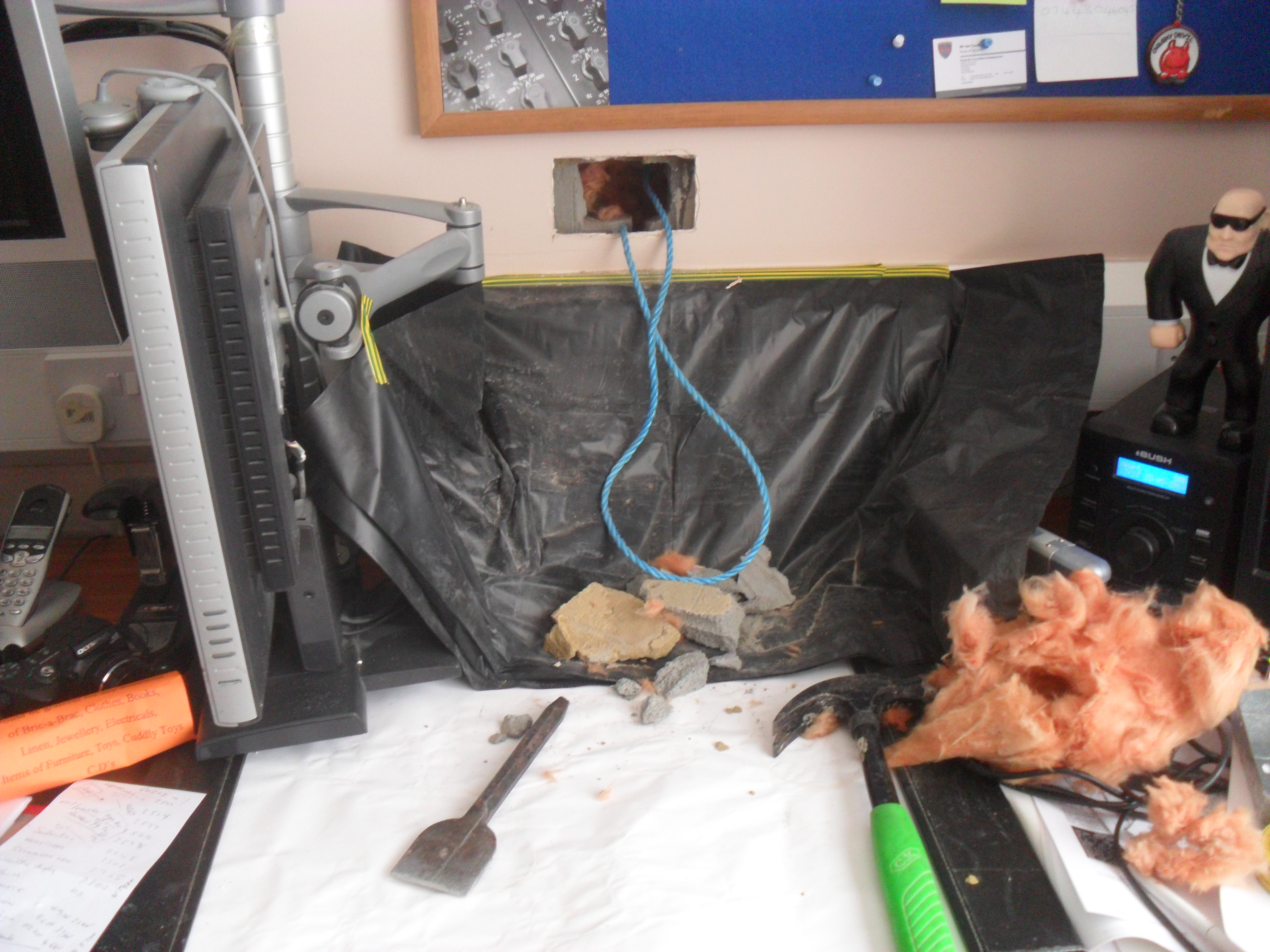
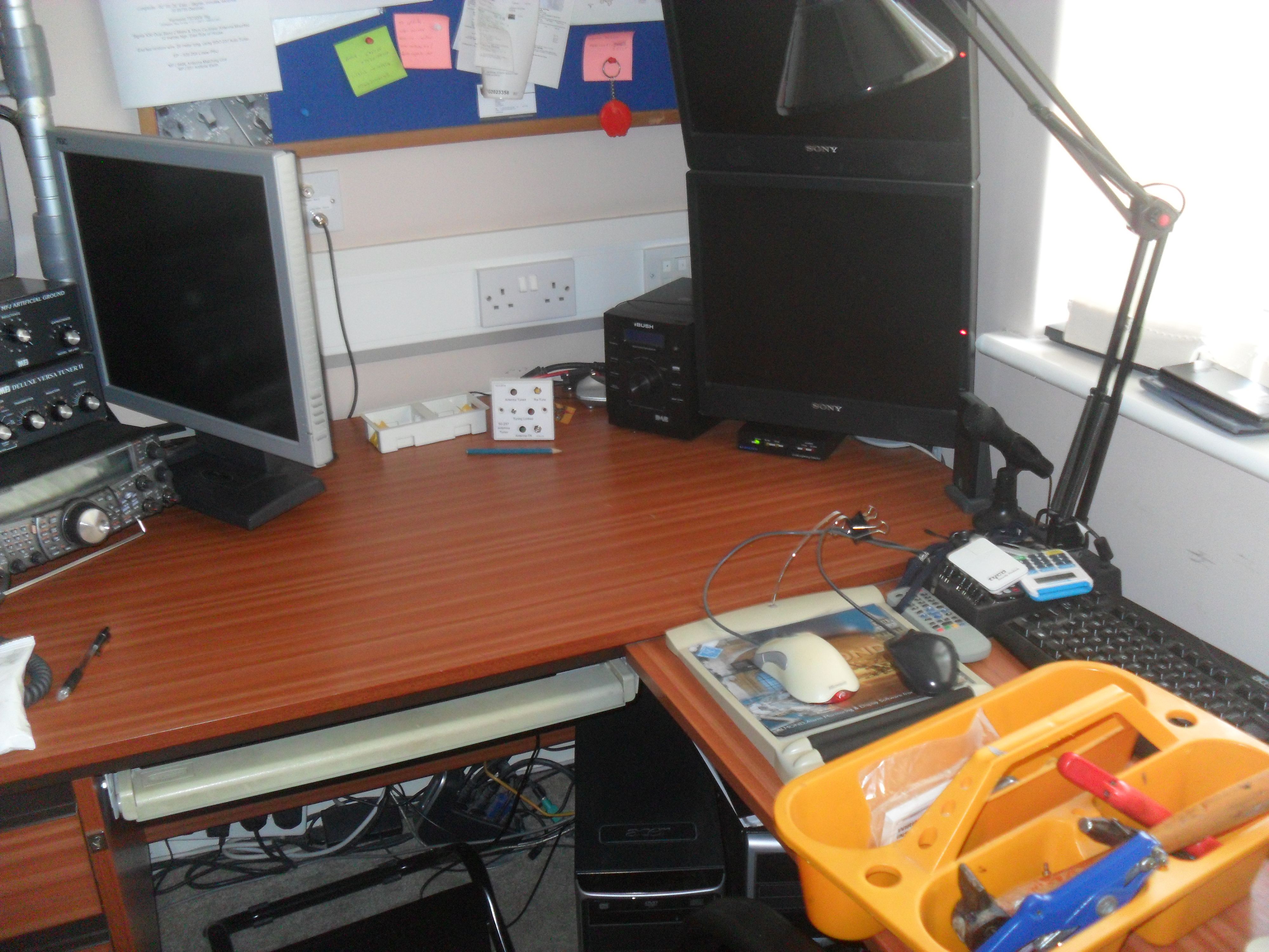
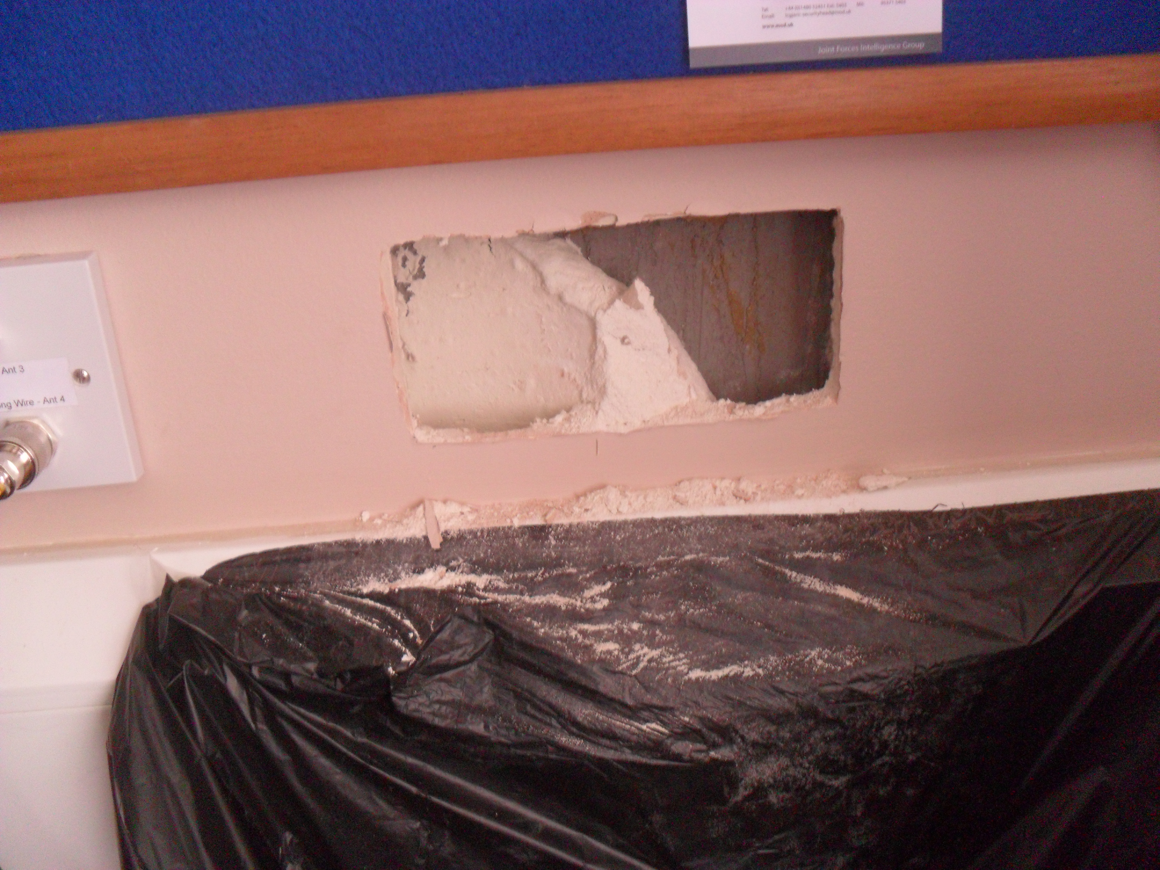
I started by clearing the area:

Preparing

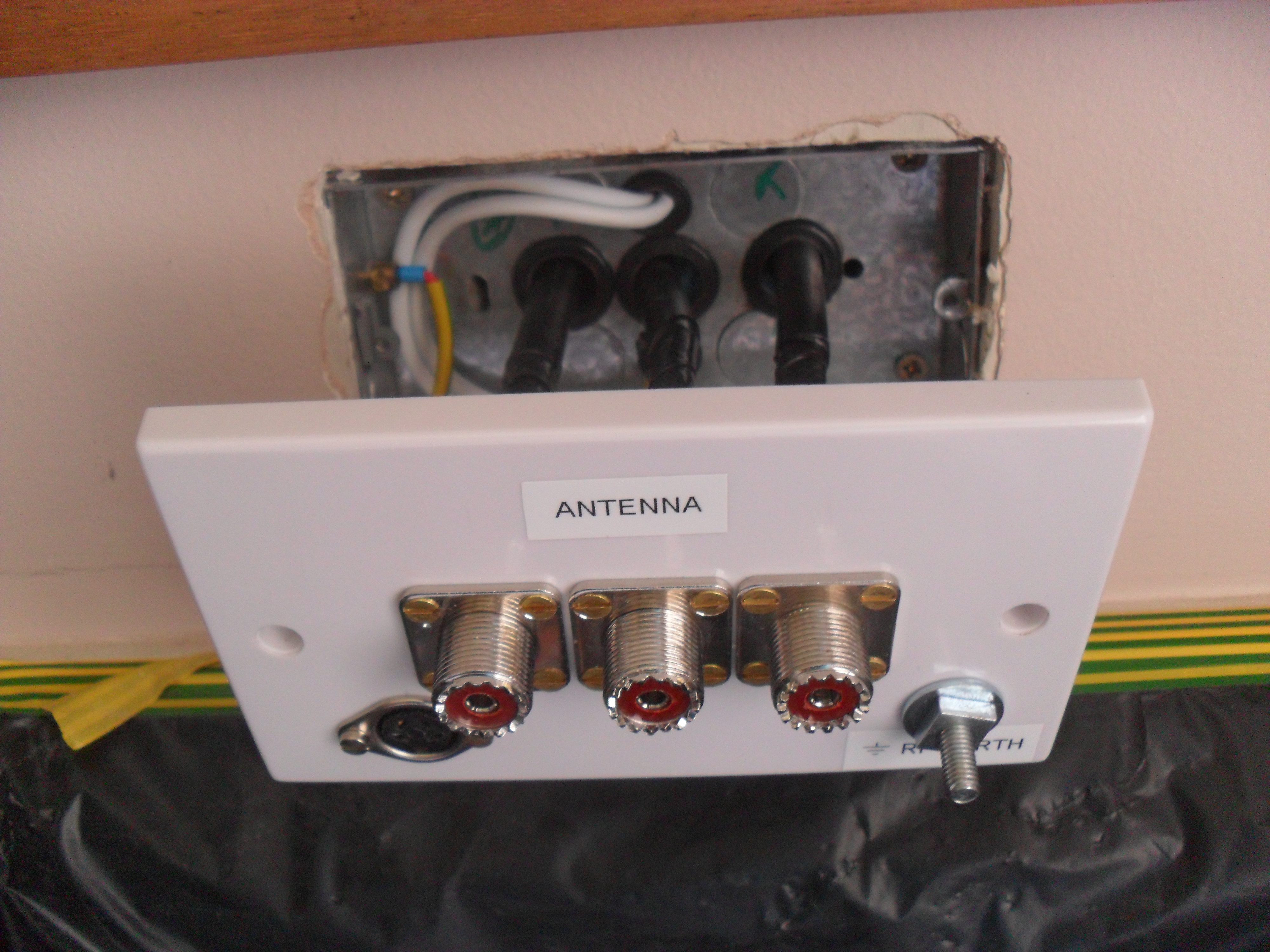
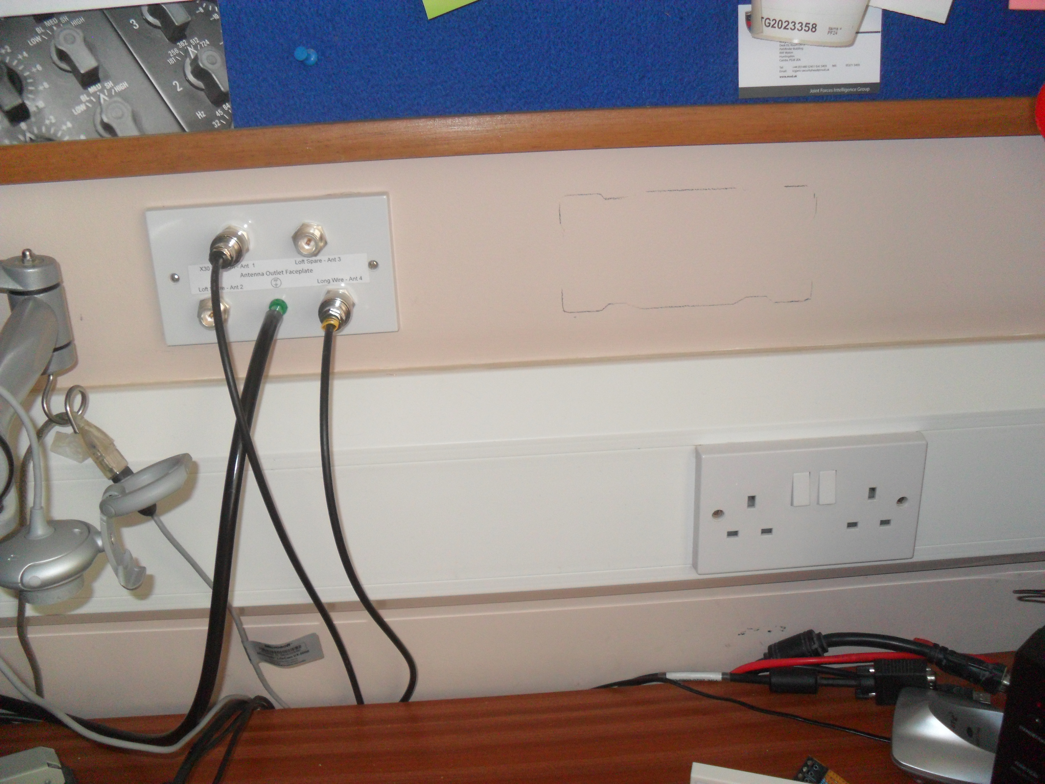
Offered the backbox to the wall and leveled it with the existing antenna faceplate:

Wall Marked

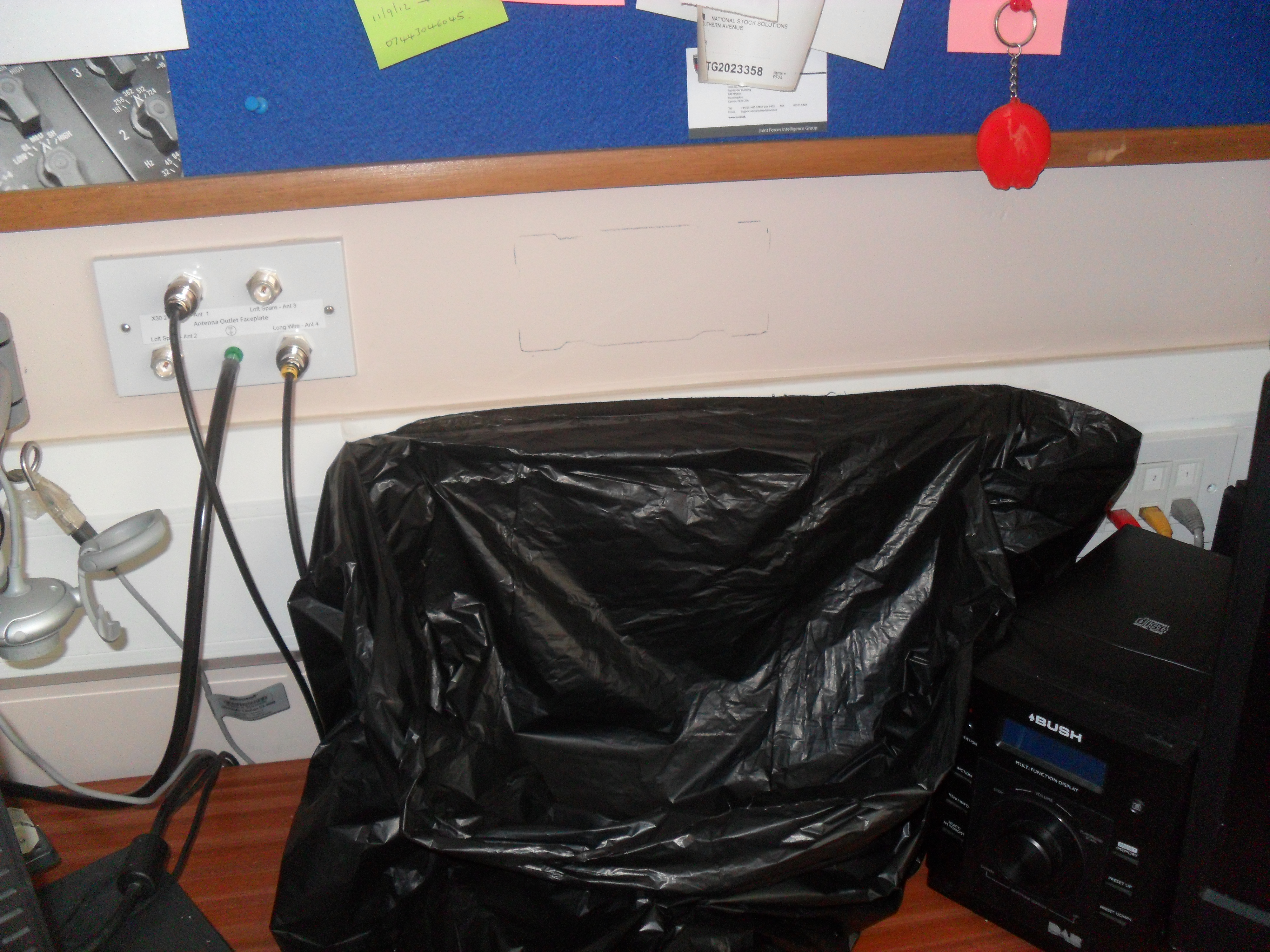
Bin bag opened and taped to the dado trunking ready to contain the majority of the mess:

Bag in place

Using a sharp utility knife I scored the plaster board along the pencil markings, repeating this a number of times until the blade cuts through (the finishing lining plasterboard is quite thin for my internal walls, so it was quite easy), you can use the alternate method of drilling a hole at each corner and cut the hole with a plasterboard saw or similar.

board knife cut

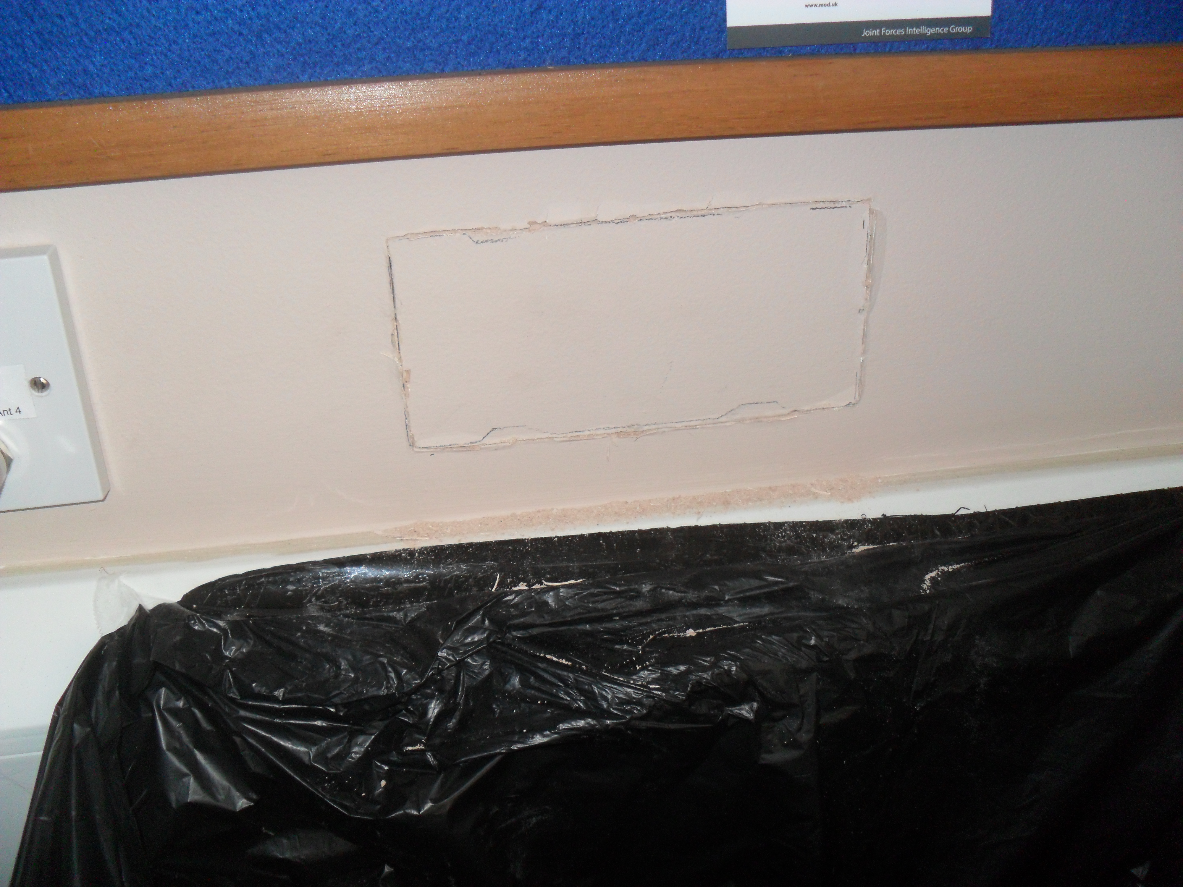
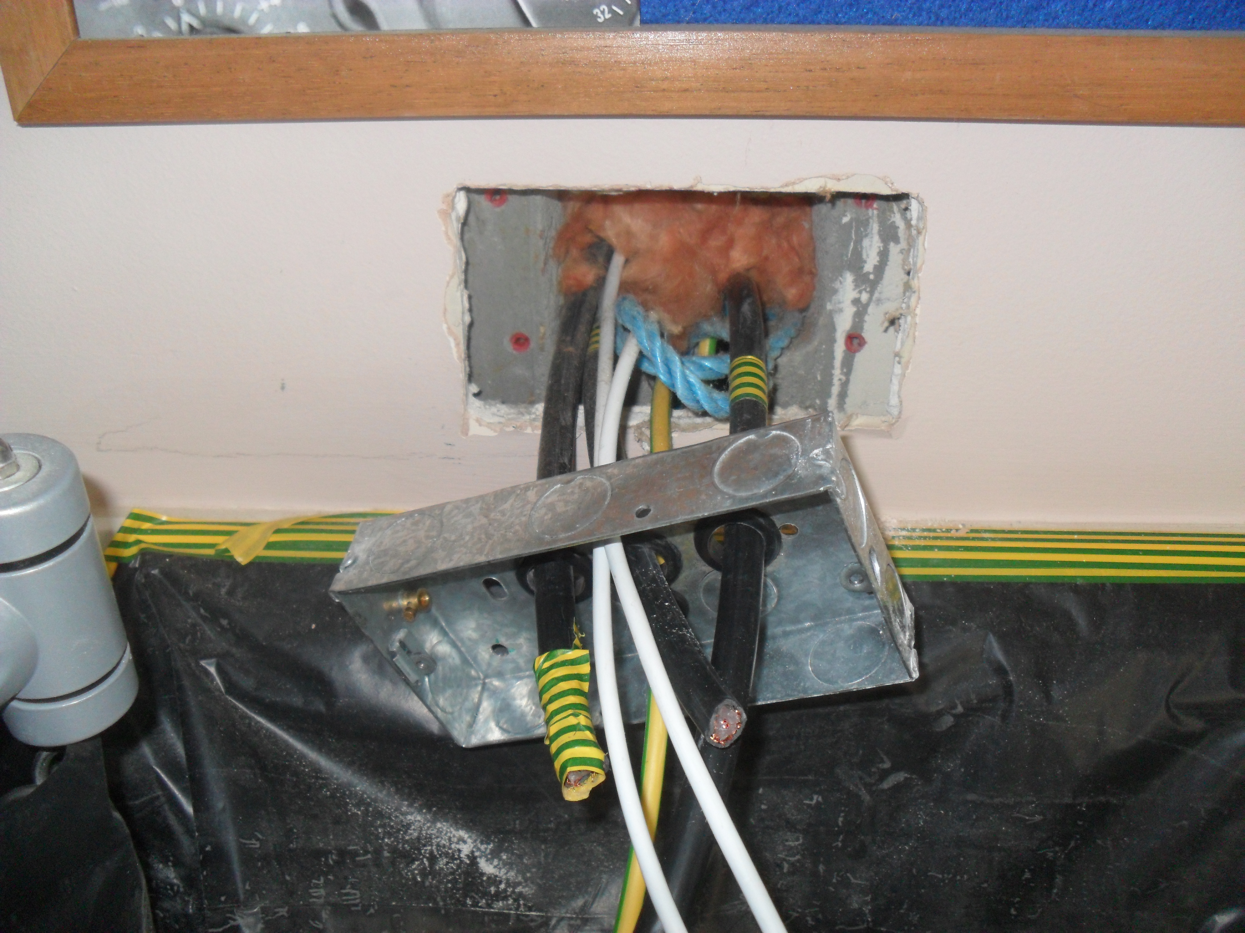
I knew by tapping on the plasterboard that the fixing adhesive was right in the middle of the hole, to break the cut board out, I split the board worth a chisel and took each piece out, I try not to let the pieces fall into the cavity between the wall and the board, the adhesive was removed using a bolster chisel, notches in the breeze block were needed to allow the fixing wings of the dry lining box to be fully pushed back to clear the plasterboard:

wall exposed

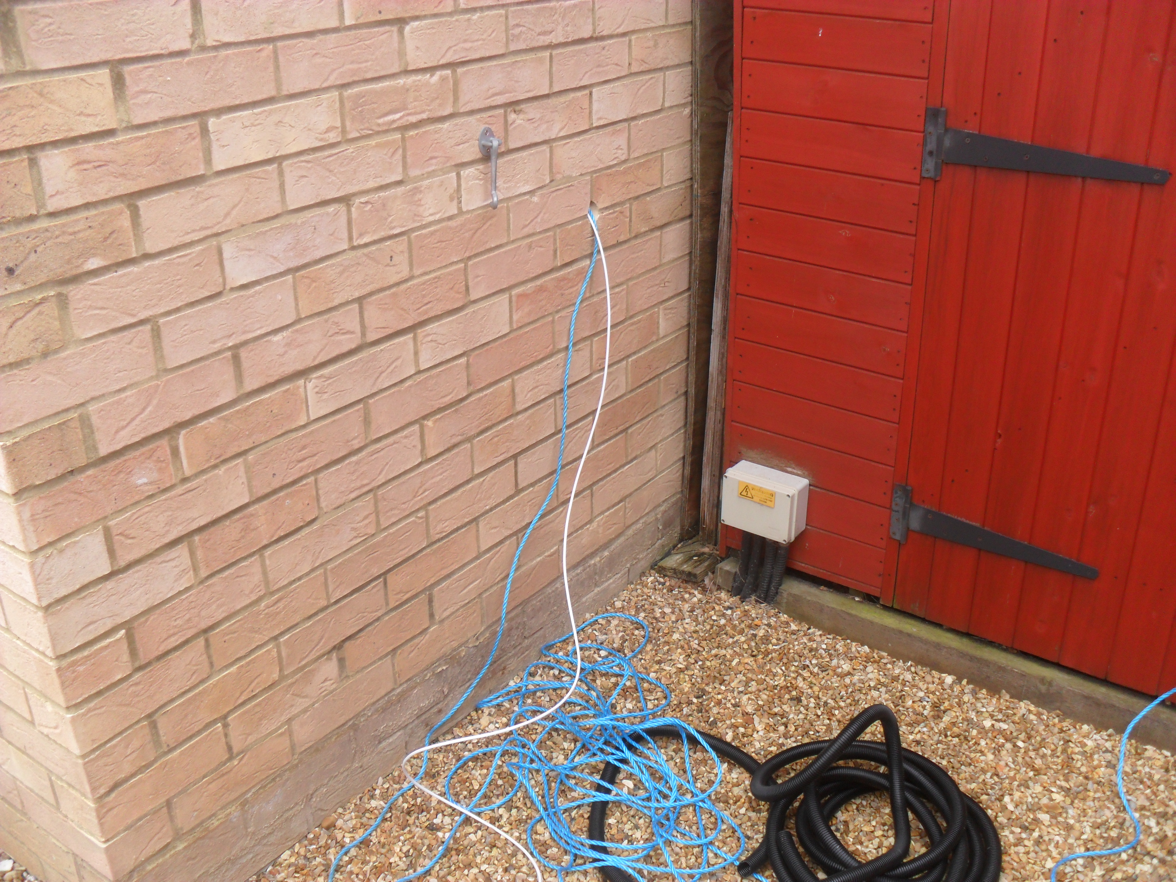
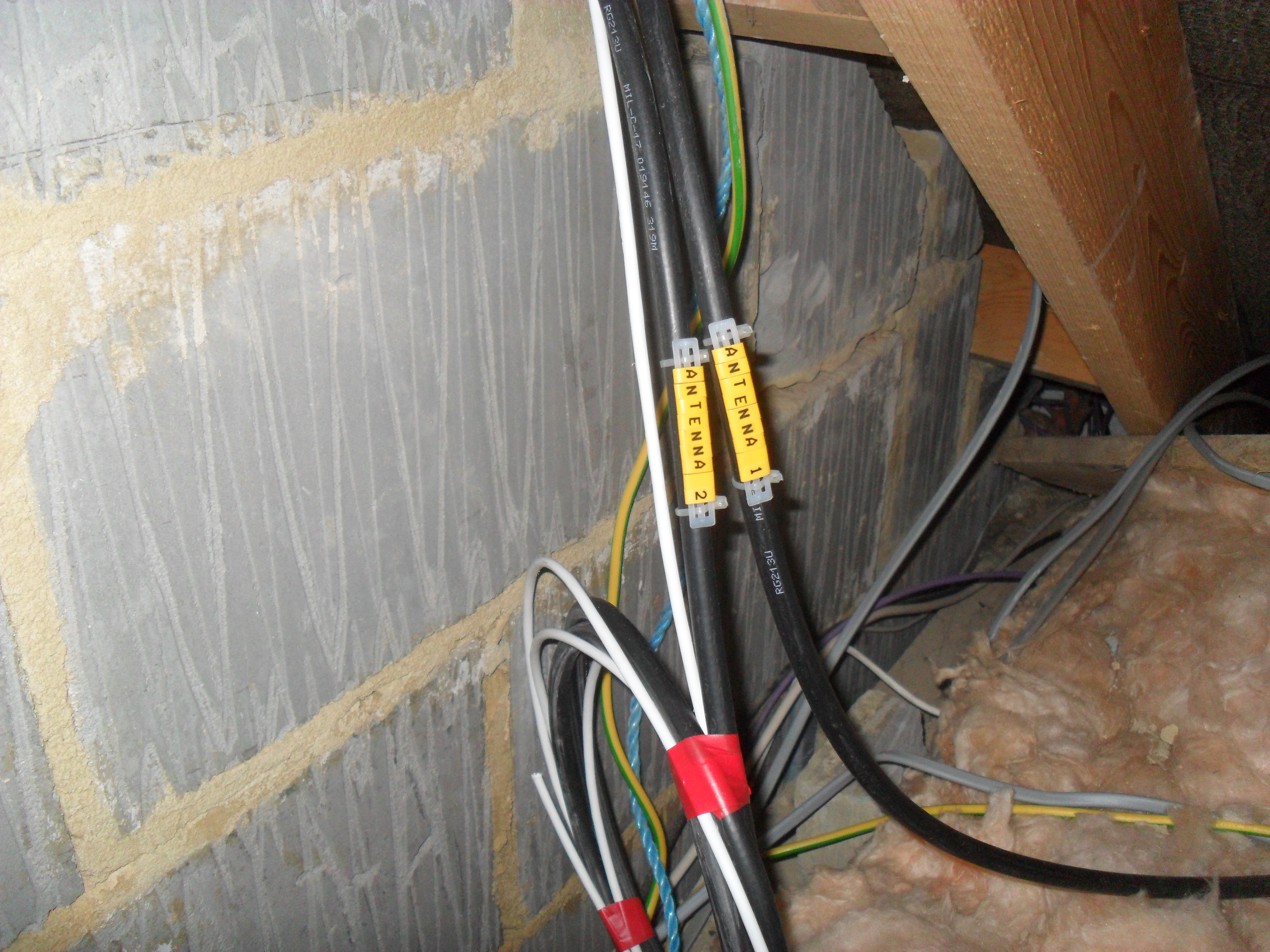
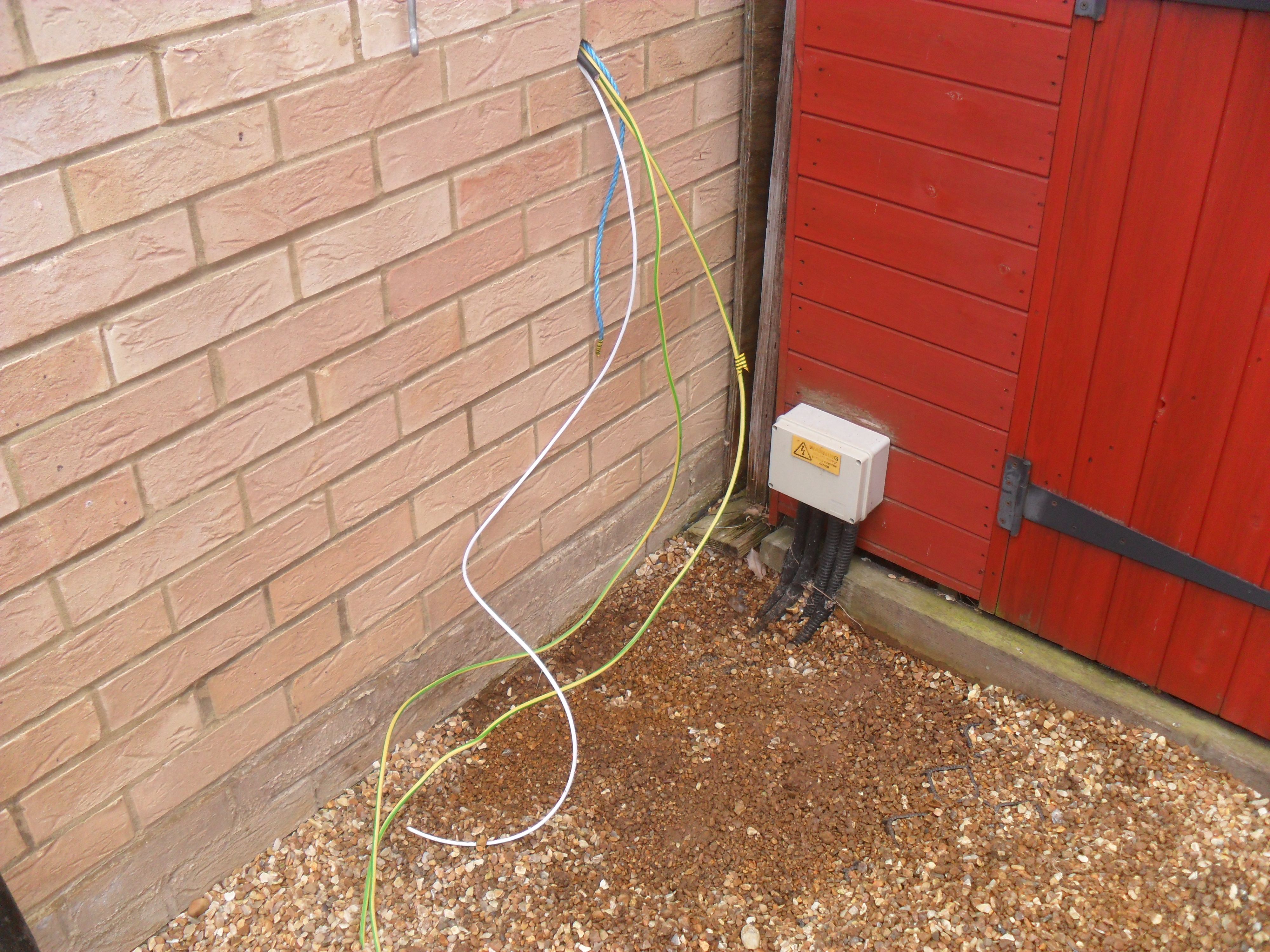
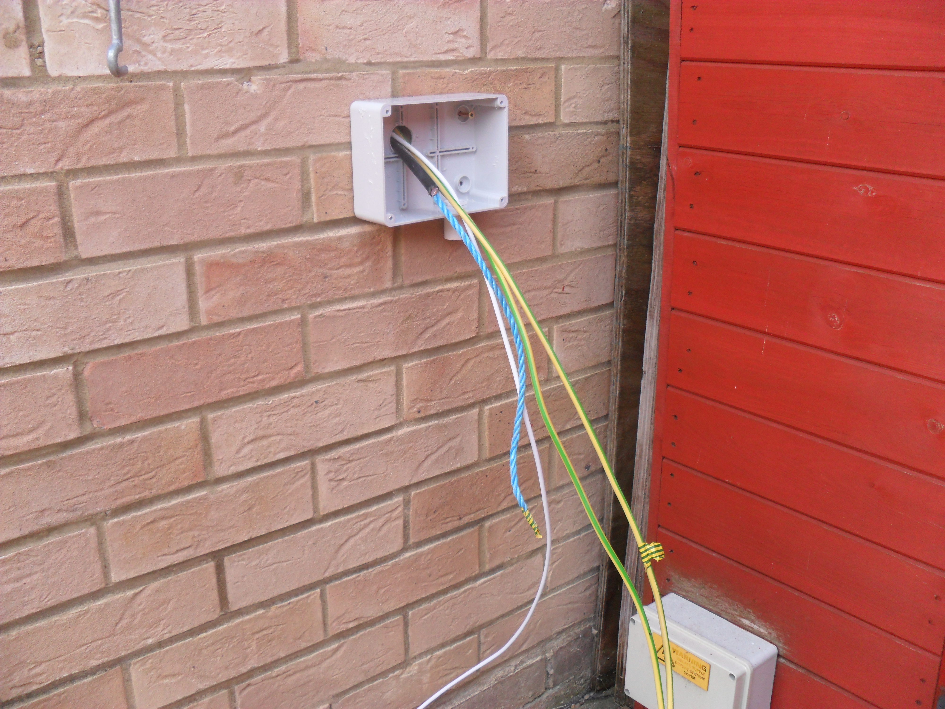
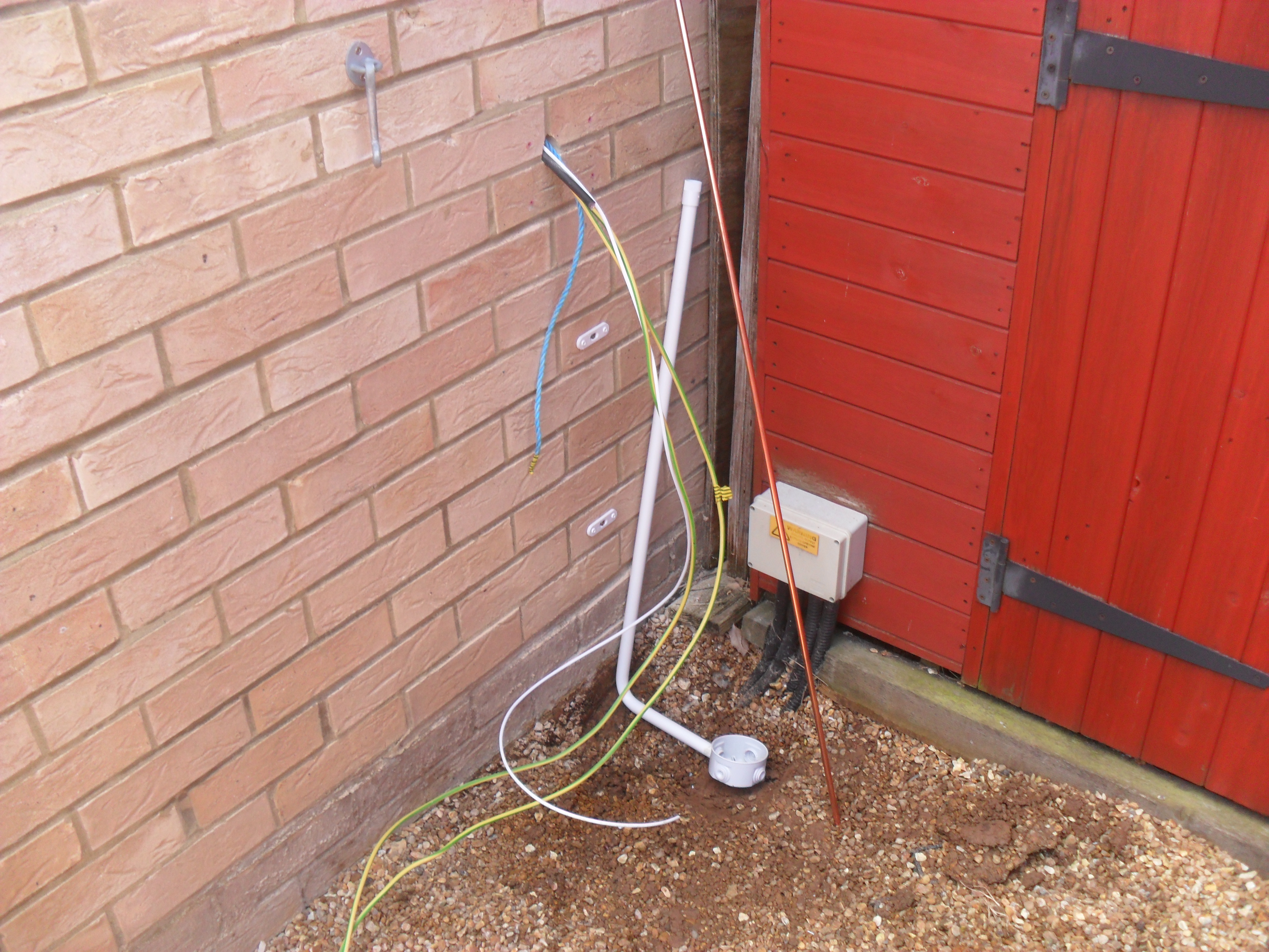
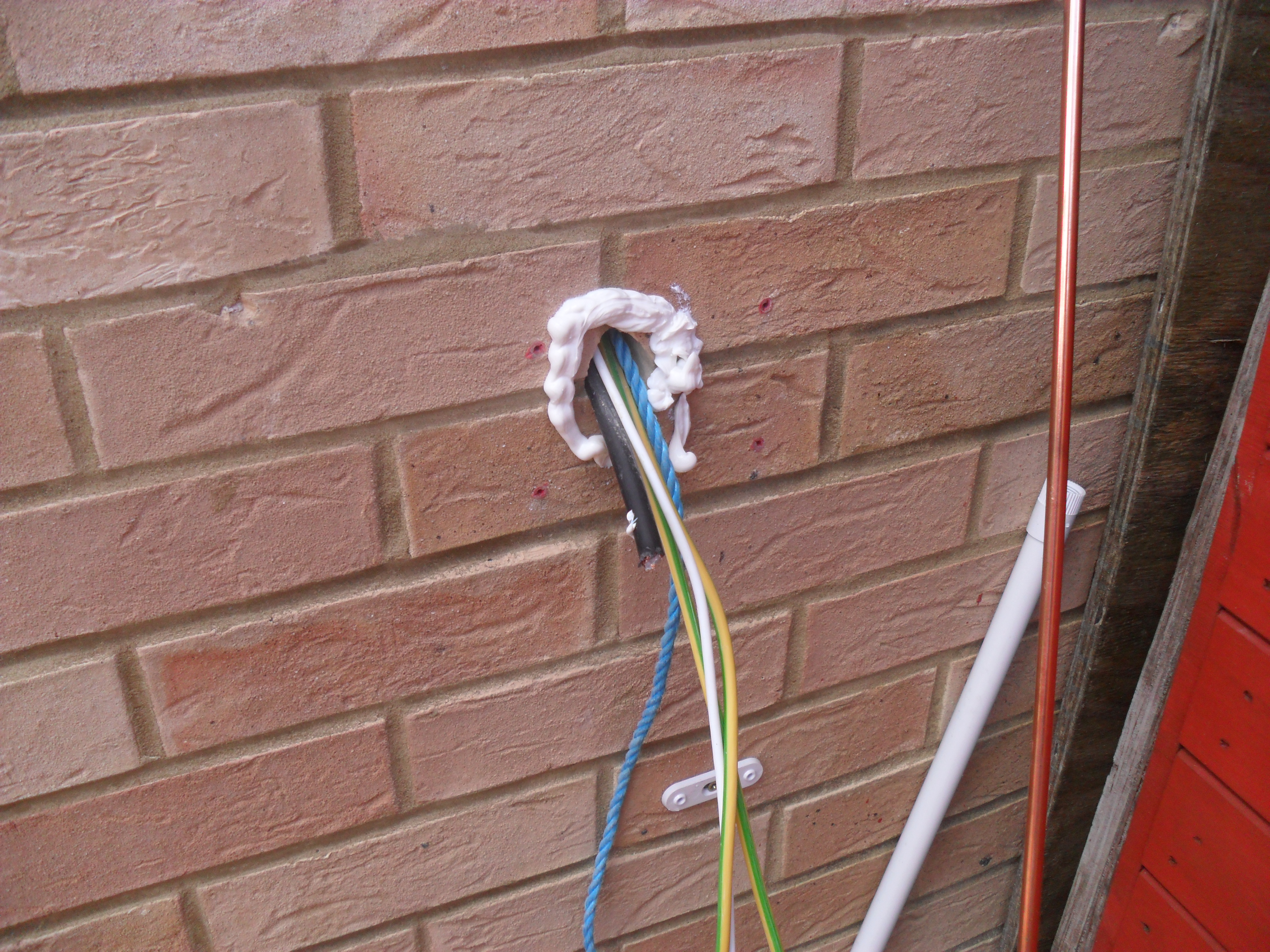
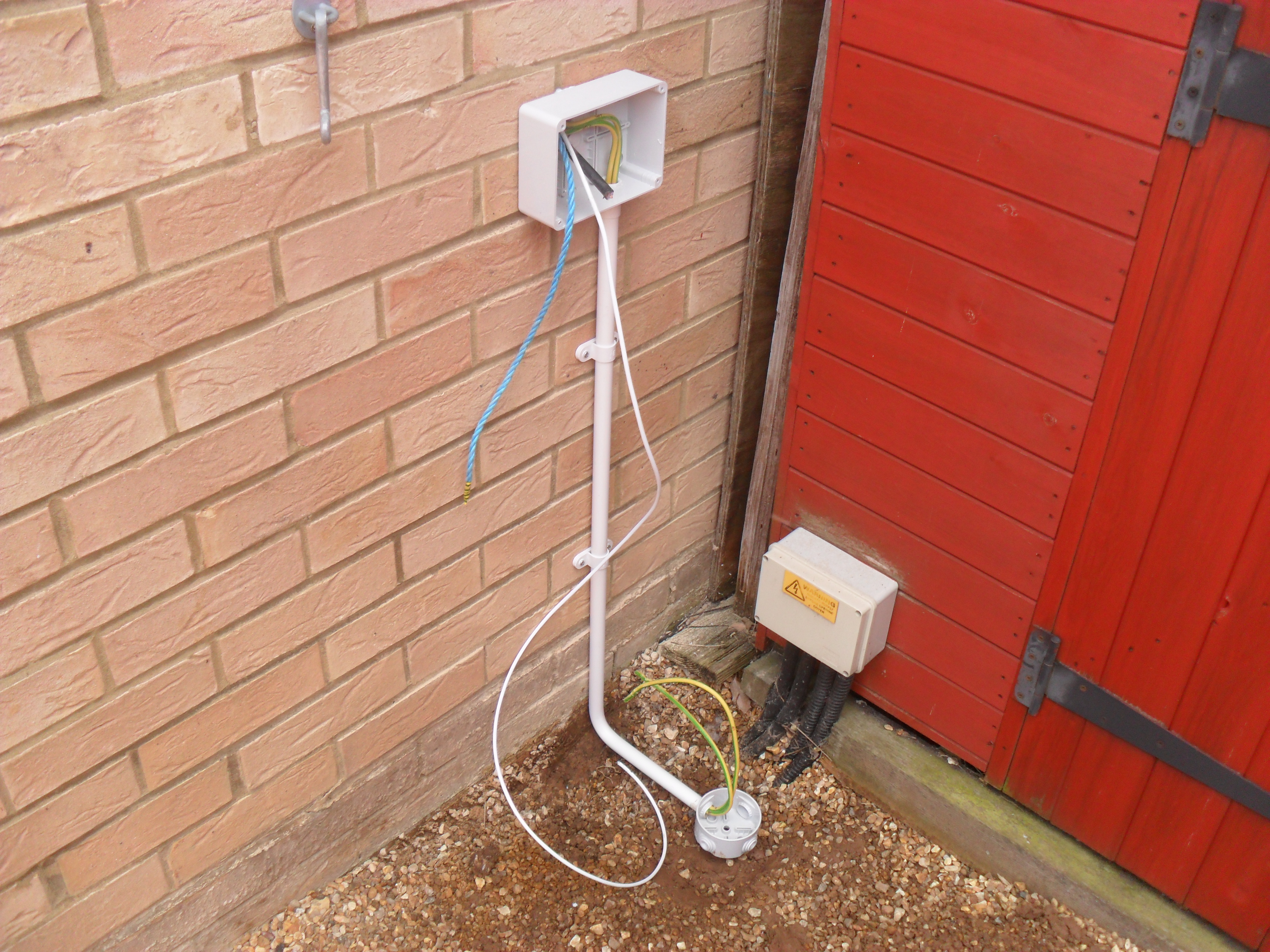
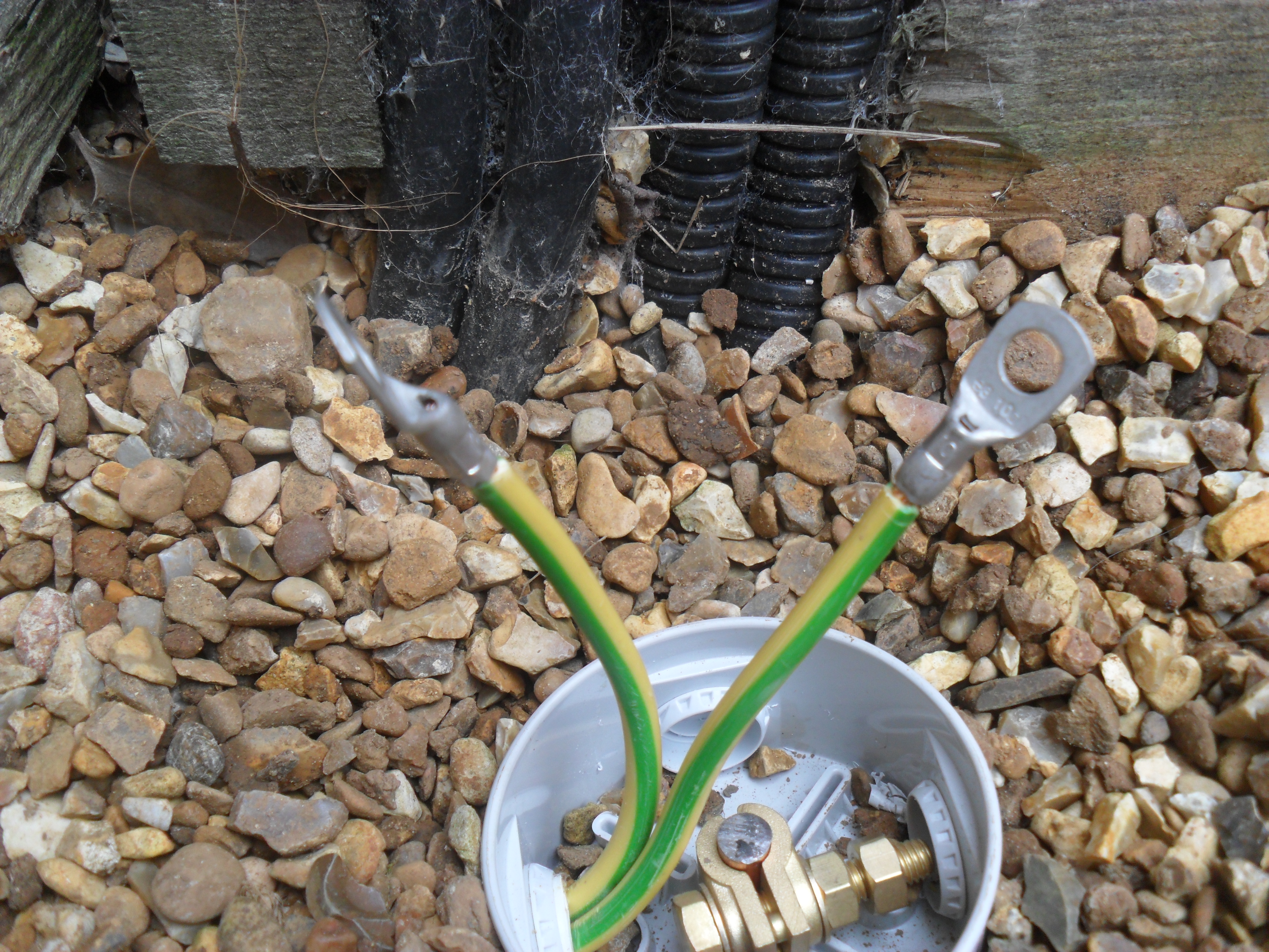
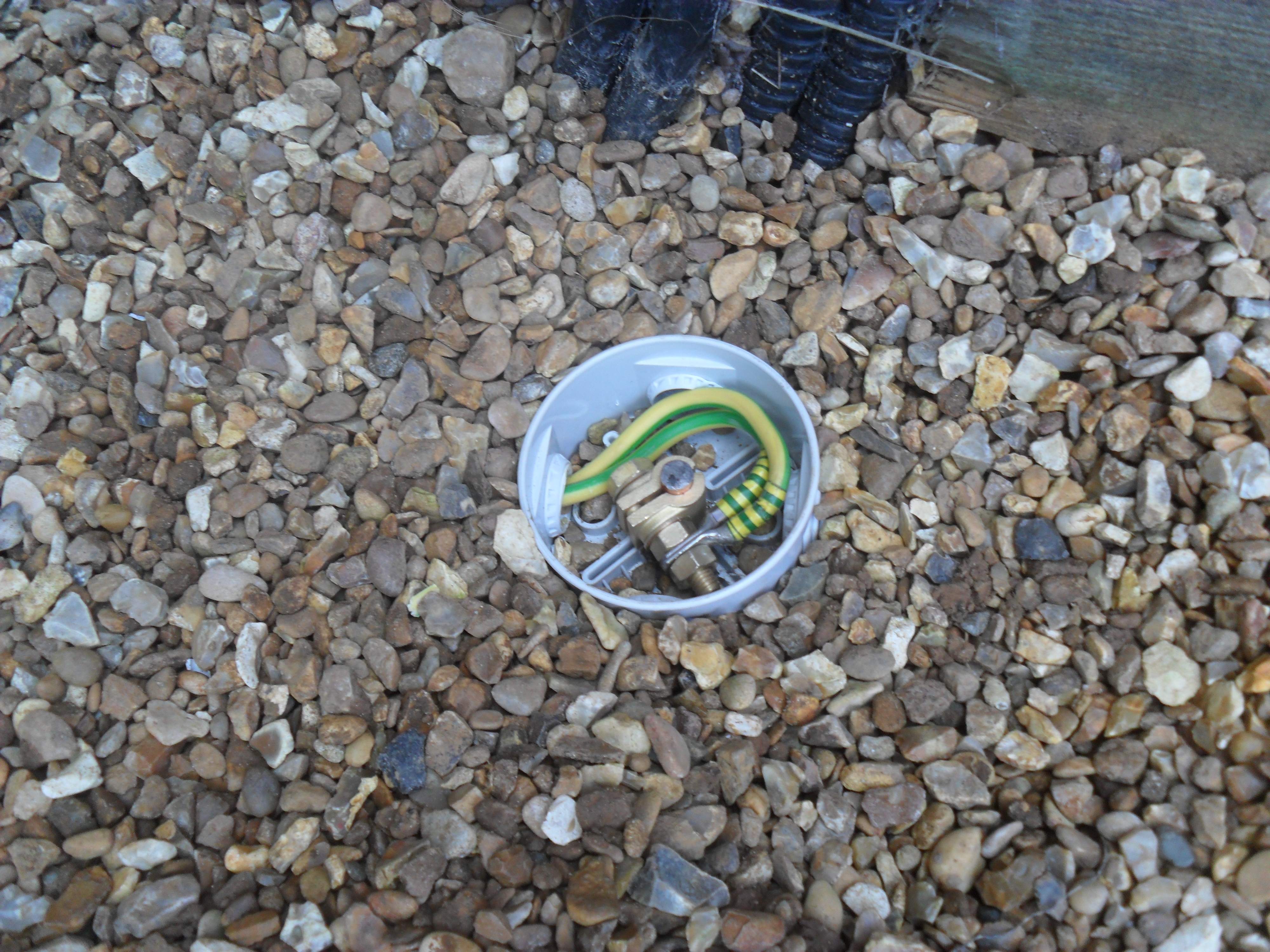
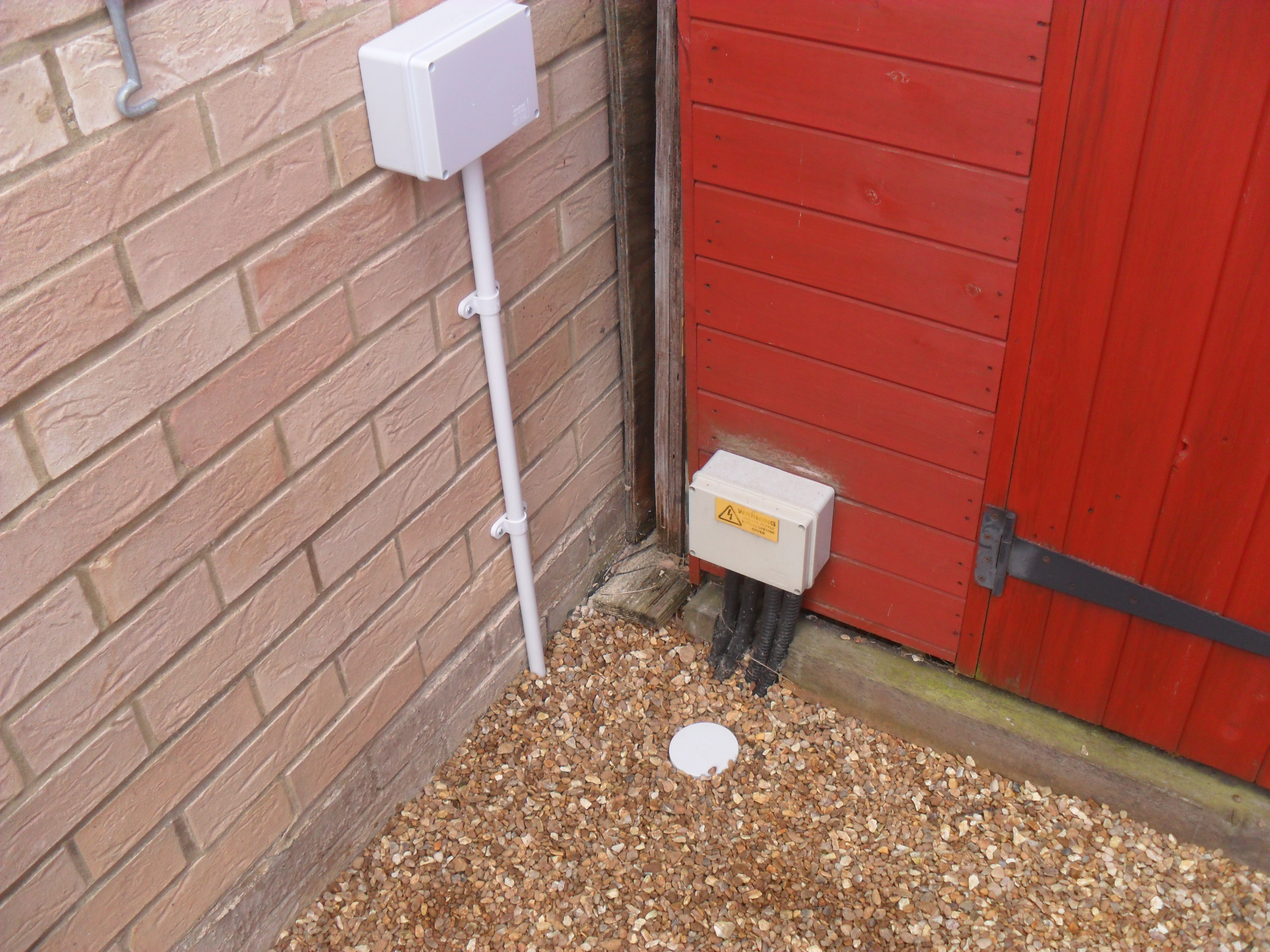
The control cable to the SG-237 tuner was put in place when I was drawing the antenna cables:

cable fished

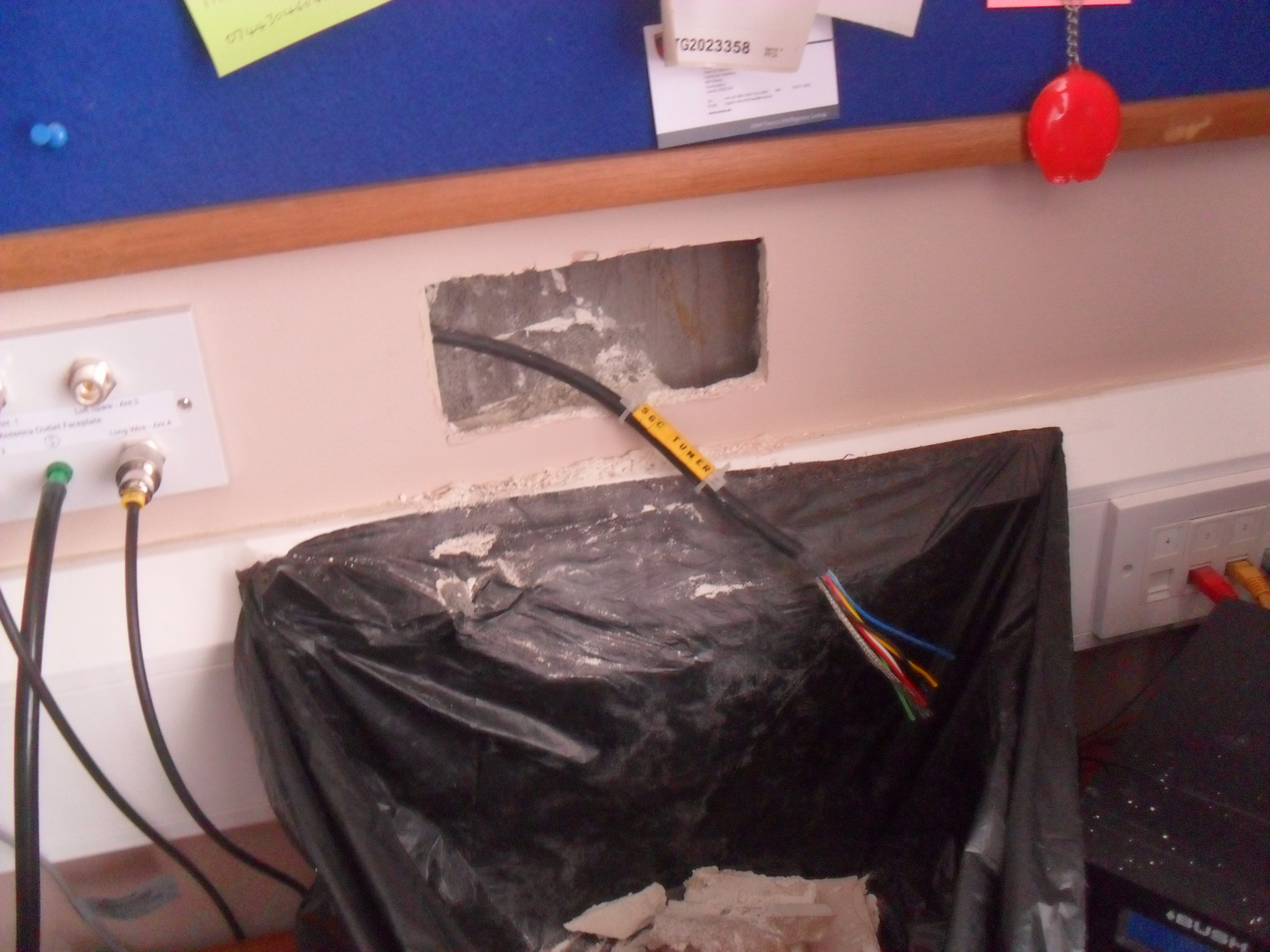
Drylining box in place with cable conductors pin crimped:

box in ends made off

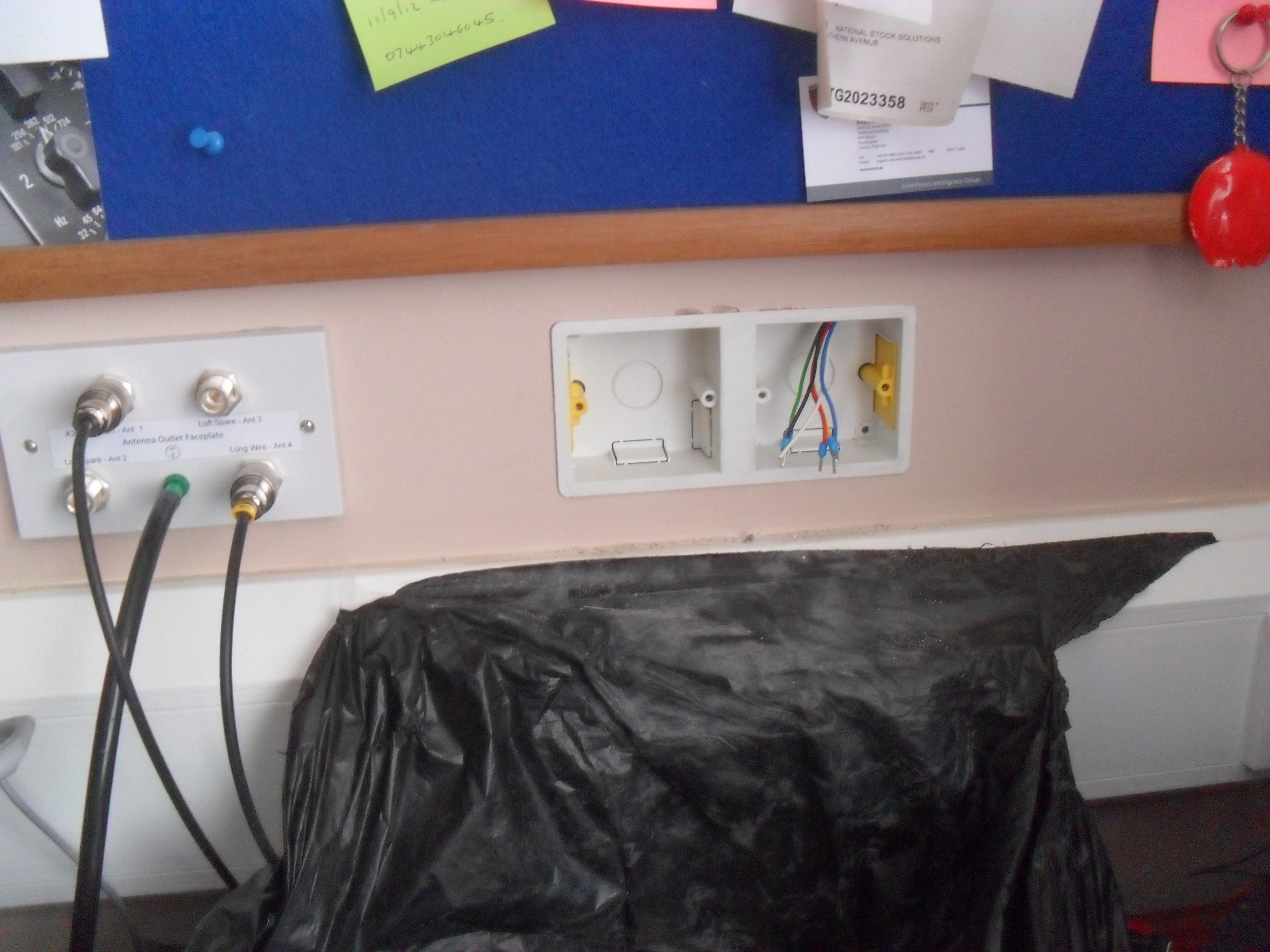
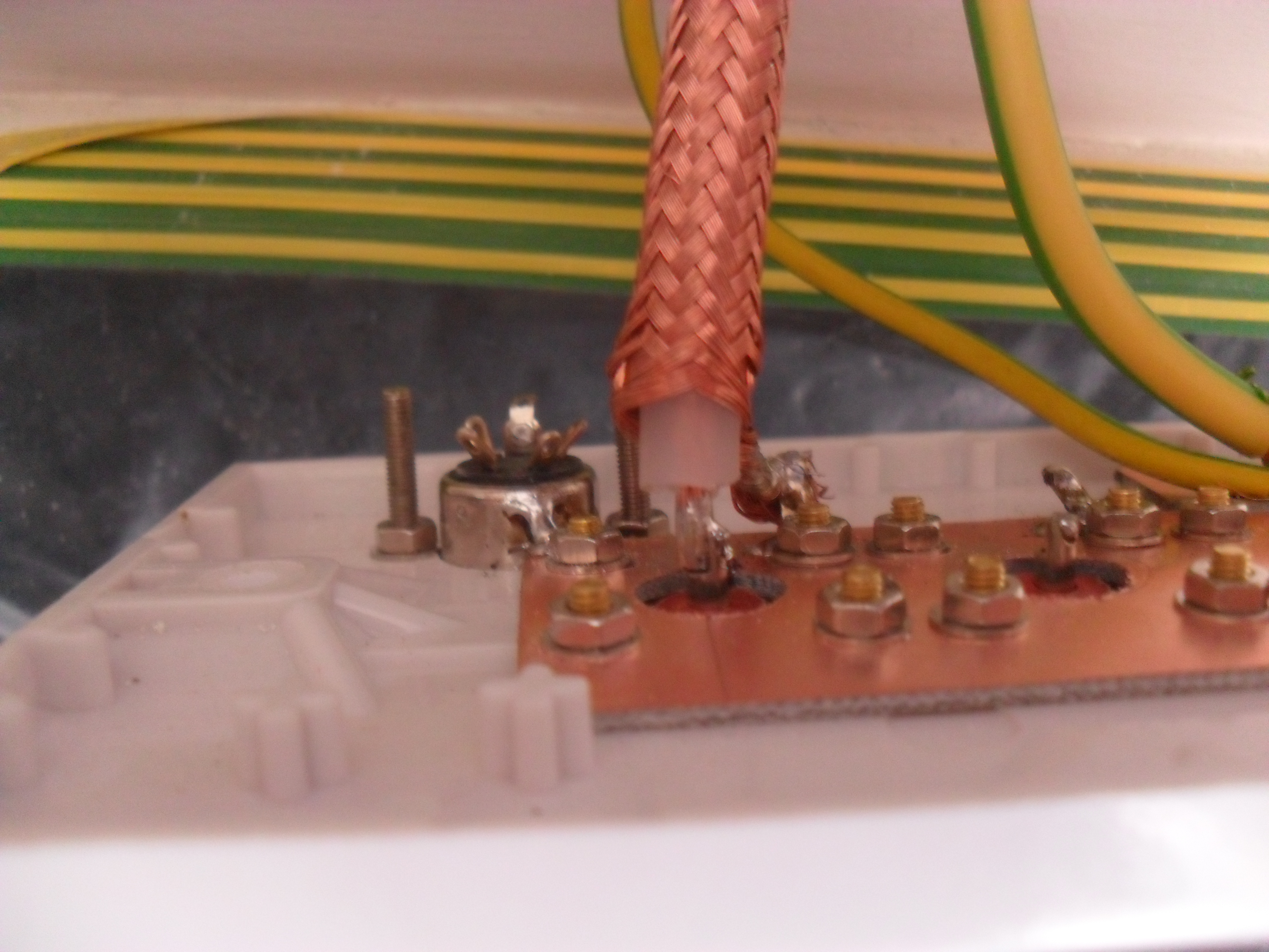
Cable connected to veroboard:

connected to veroboard

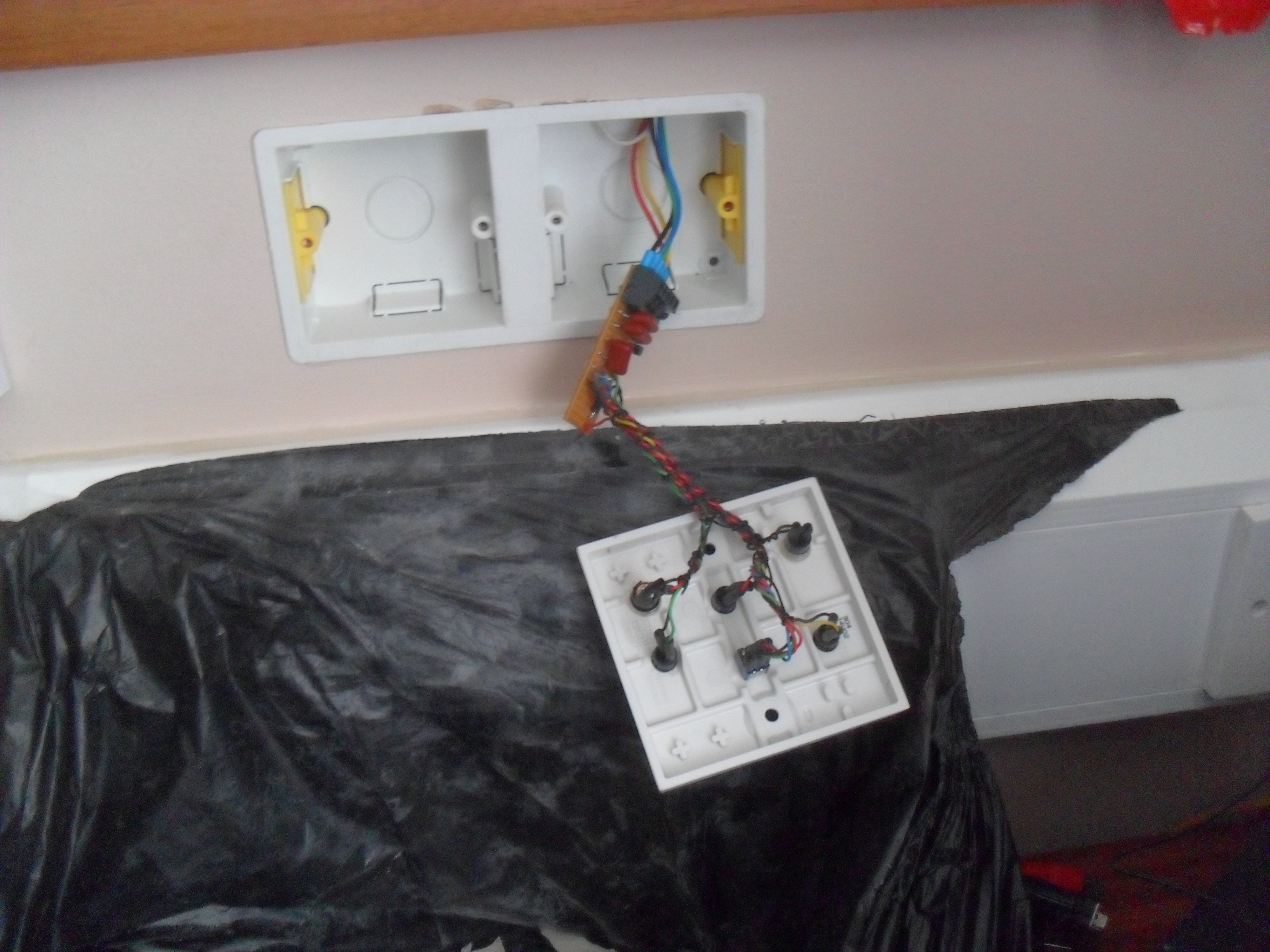
Veroboard sized to fit within rear of backbox:

vero in backbox

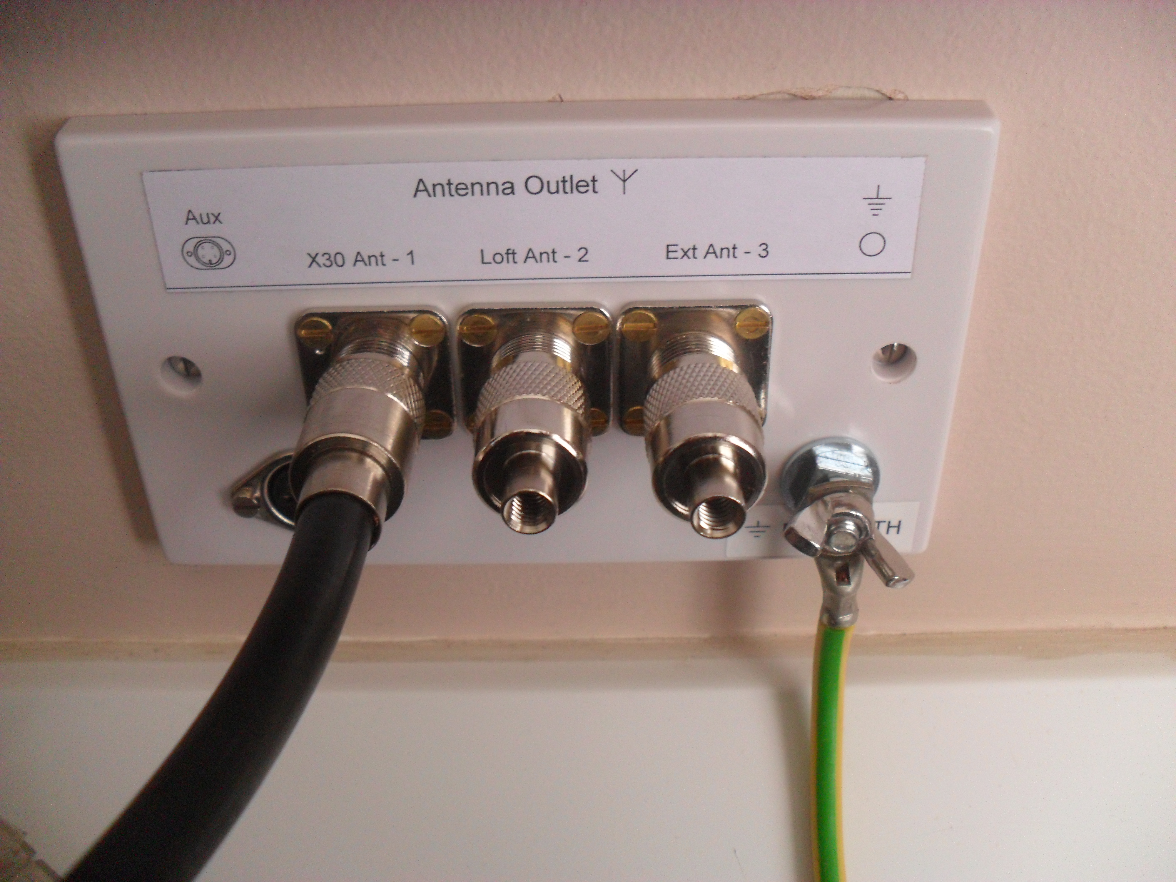
Faceplates screwed on and area cleaned up:

faceplate on

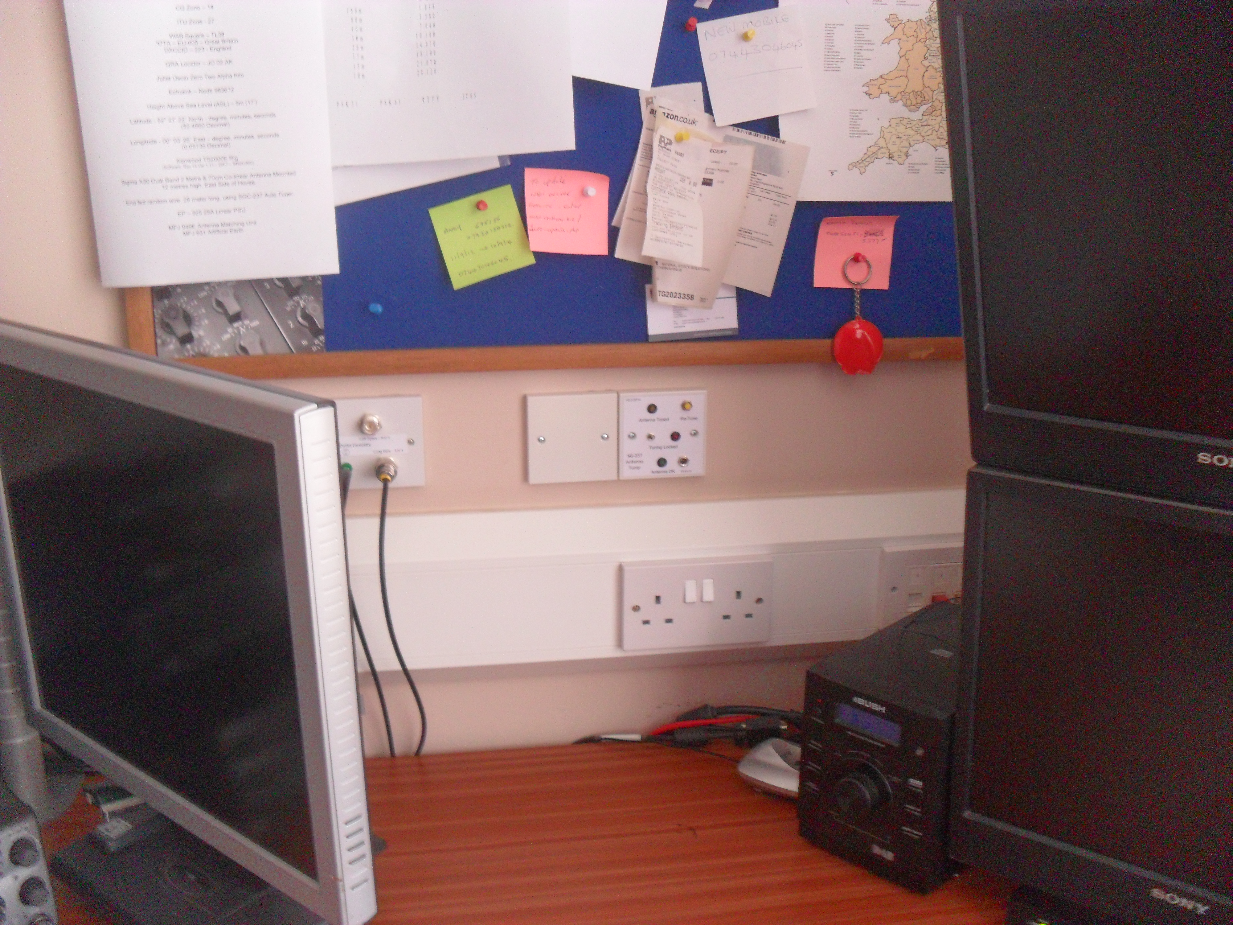
Job done, 12v wall wart PSU plugged in all ready for Part2 hardware and long wire installation.

back together

Click for part2

Intermediate Call Sign

Received my Radio Ham pass confirmation today, logging into the OFCOM website, I have the new callsign of 2E0DDI, I don’t think I’ll change all my details on QRZ.Com and other forums just yet from M6EID as I’m considering taking the advanced license test in the next few months.

My Humble Radio Setup

I have hopefully finished battering the credit card (well for now), and have the radio and ancillaries, the next purchase will be the external aerial, but I will do another page on that.

I decided on a Kenwood TS-2000 multi-band transceiver as this will give me all the flexibility I believe I require, this is powered by a EP-925 PSU with an output current of 25A and a peak of 30A. All the reviews on this power supply were right in that it is really noisy when the cooling fan kicks in, I have done the mod which is all over the internet and is simply a 1.5K resistor in series with the thermostat, this ‘fools’ the cooling fan circuit and has the fan running at a very low speed all the time, should the thermostat open due to high temperature, the fan will go to full speed and full cooling.

SAM_5009

I also bought a Signalink mainly in preparation for PSK31 when I get the aerial sorted, I will also explore all other data modes when I get the chance, the Signalink is configure to Radio Ham Deluxe program and works really well, again I copied others in downloading Skype so I can remote into the TS-2000 from a laptop, currently my license allows me to do this only from within the house as it is still classed as being attended, a full license holder can use this in remote mode away from the house.

I imported a MFJ-949E Antenna Matching Unit, this is not connected to anything yet, but looks nice 🙂

SAM_5012

Passed Intermediate Test

Undertook the Intermediate License radio amateur Test under the watchful eye of Cambridge University Radio Club who kindly allowed me to take the test with them, even though I’m not a member, or for that matter ever got past going to a comprehensive school!

The test comprises of 45 multiple choice questions on all aspects of the syllabus, once the test is over, the invigilators provisionally mark the paper straight away so you know if you have passed or not.

I got two questions wrong, and although you do have to wait for official confirmation, I’ve passed….Yeah.

Started on Ham Infrastructure

After a bit of surfing I decided on installing a Diamond x30 antenna, this has been fitted to a 9′ cranked offset pole, I have mounted this next to the soil vent stack so that the bracket and supporting pole are partially obscured from my immediate neighbour on my right, that said, the assembly doesn’t look that bad and cable management in the form of 50 x 25 trunking dropping from the soffit blends in somewhat.

x30 antenna
x30 antenna

I used RG213 cable, this will terminate in a double gang faceplate housing 3 x SO259 sockets, one socket is for the x30, one will be for a spare outlet in the loft and third will go to an external aerial which I have yet to decide on, cable routes have been found to outside down the cavity so that it ends a neat install, this route will also carry the stations RF earth.

Draw rope to attic via 30mm hole

This shows the draw cord disappearing into the cavity ending up in the loft, I used a 30mm core bit at an angle of about 60 degrees to make the hole in the wall, once drilled, I used two lengths of 16mm trunking lid fixed together to get the right length to push up through the wall insulation. Fishing the trunking lid out in the loft is a two person job and a used a walkie-talkie with my better half, to get at this in the loft meant I had to take half a breeze block out as well as the skin off the back of my hand!, once captured, I affixed the draw cord and pulled the trunking lid out, pulling the cord down the cavity.

2014-05-23 01.07.39

First wire to be drawn into the loft was an 6 core 7/02mm signal cable, this is looped out at the breakout faceplate and will allow me to add peripherals such as RF relay, rotators or powered equipment.

2014-05-23 01.08.33

As my walls are ‘Dot and Dab’, meaning that the breeze block walls instead of being directly plastered, have blobs of plaster board fixing cement all over the place with the plaster board sheets being pressed against this and levelled, the board is then given a finishing skim of plaster, to make sure you don’t make a hole directly over a blob of fixing cement, tap the board with your hand and you will hear the sound change form ‘hollow’ to ‘solid’ as you work your way around the area of interest, if you have no option but to make your hole where it sounds solid, good luck!, I found a hollow spot in the region where I knew the draw cord was in the cavity, marking round a double metal backbox, I kept scoring the plasterboard with a utility knife until the cut board came out exposing the breeze block, using a 8mm drill bit, I chain drilled and then opened the hole with a bolster chisel. Using a brazing rod with a hook formed in the end, I managed on the forth attempt to hook the draw cord.

2014-05-23 02.16.16

The image shows the RG213 from the x30 antenna and the longer RG213 which has been pulled up from outside, this will be looped, and pulled into the loft space.

2014-05-23 03.33.23

Backbox ready to be pushed into position, the cables you can see are three RG213 (x30, spare to loft and outside), signal cable looped from outside to the loft and a 10mm earth cable which goes to multiple earth rods, I earthed the x30 antenna bracket with a separate 10mm cable, also terminating at the earth rods.

2014-05-24 00.54.08

RG213 soldered onto the faceplate bulkhead SO259.

2014-05-24 04.11.37

All antenna cables soldered and for good measure I shielded the connections with bonded copper tape.

2014-05-24 04.11.46

Faceplate being eased into place.

Modified face plate

All secure, newly labelled faceplate with DIN socket for the signal cable, this will be used for a future requirement.

loft cable markers

Cables identified in the loft.

SAM_4943

Ground for earth rod being prepared, this area does not get the sun and with the gravel on top, the heavy clay is always wet, so an ideal spot, I did have to be careful of existing cabling and the drains with run close to the wall. The rods and enclosures came from www.tlc.com.

SAM_4944

Loose fit of the enclosure allowing measurements to be made for the conduit.

SAM_4946

Conduit bent and saddles fitted, in the picture is the 4′ copper coated steel rod.

SAM_4947

Silicon sealant around the cable exit, the enclosure will be screwed against this making a good water resisting seal, this sealant dries clear.

SAM_4949

Hardware fitted and earth cables ready for termination.

SAM_4956

10mm lugs crimped and ready to be soldered for good measure.

SAM_4958

Connected to the rod clamp.

SAM_4959

Lidded up.

SAM_4961

Even Barney couldn’t find it when covered.

SAM_4963

Inside the enclosure cables are labelled, I might put an earth block in here connected to a external antenna surge suppressor at a later date.

2014-05-25 21.57.52

This where the faceplate lives in relation to the office, as you can see it is absent of radio kit as I do not own any yet, but I’m working on it!

2014-05-25 21.57.26

Office put back together and faceplate covered by PC monitor, now the route to the loft and outside is established, modifications or extensions to the cabling can be done relatively easily.

The next stage is the addition of multiple earth rods, so please keep checking back.