Category Archives: Ham Radio

Study – Never to Old

I’m currently studying for the Advanced License exam which I would like to attempt in December 14, the sites that have training material freely available are:

BRATS
Chelmsford ARS

To test progress Hamtest have online mock exams, sample RSGB papers can be downloaded from here.

A superb downloadable program for your PC is available from G3KZB called QADV, this is a great program to assist learning as it has a huge range of sample questions allowing you to view your strengths and areas for development.

If you know of any more, please let me know using the contact form.

SWR of Inverted ‘L’

Their is a great saying that ‘if it ain’t broke don’t fix it’, I was reading about the optimal (link to random length article) length of antenna wire, my overall wire length is 30m rather than at one of the optimum lengths specified in the link, one of the indicators apparently was if the auto-tuner tuned to perfectly, then it is not optimized for all the bands that the tuner can tune to.

According to the article, my antenna length should be 25.6m, so I loped 4.4m off the end and gleefully went to the shack to see what a dramatic change this will have made, well it used to tune on 80m and now it doesn’t 🙁

The ladder came back out as did the soldering iron and heat shrink, I now have it back to as it was and I won’t make that mistake again!

The table shows the results of the SG-237 tuning a 30m inverted ‘L’ wire at 6m above ground:

SWR Tuned Readings
SWR Tuned Readings

Lesson learned or is it now Lesson identified.

Pt 4 Longwire Installation – Final

This is the final part in the installation journal, the first bit was to mount the end bracket which secures and terminates the antenna wire to the side gable at the front of the house, I used the ‘T’ from a galvanized TK type bracket, the one used was 24″ in length and secured to the masonry by 2 x 10mm expanding shield anchors.

To fit the insulator to the ‘T’ bracket I bent a small length of M6 threaded stud bar round a scaffold pole, to enable the insulator to slide of the exposed threads of the stud, I slid the braid from a length of coax over it and secured that with helleman sleeves at each end.

2014-09-13 04.38.46 (Medium)

The existing TV pole and brackets were removed and the ‘T and K’ brackets were replaced, as were the securing fixings and pole brackets, this TV Pole also support the Weather Station anemometer and Direction sensor, so this was the reassembly order:

Nipped the pole up in the bracket and inserted the wind & direction sensor and pole into the top of TV pole and secured with machine screws, the pole was then pushed up slightly to allow me to add a log periodic TV aerial, the reason for replacing the existing TV aerial was to reduce windage loading on the pole.

The cables for the sensor and TV aerial drop within the pole exiting at the bottom before using conduit to pass through the wall.

Below the aerial is a bracket which secures a small length of pole at 90 degrees to the main pole, this has pulley’s which enable me to lower the insulator for maintenance.

2014-09-13 04.38.17 (Medium)

The pulley parachord is secured with a halyard:

2014-09-13 04.38.31 (Medium)

Couple of pictures which show different views of the antenna wire up:

2014-09-13 04.37.34 (Medium)

2014-09-13 04.37.57 (Medium)

2014-09-13 04.39.04 (Medium)

SAM_5184
The mod to this arrangement will be to replace the parachord with Dacron cord as I believe this is a more robust cord against the elements including UV.

Pt 3 Longwire Installation

Planning permission was granted today (10 Sept 2014 –  Ref:N9ZIWLHE01U00 ) for the installation of the 6m pole and longwire, in preparation I had mounted the 100mm x 100mm post and drilled the holes ready for the fixing saddles, this is a photo journal of the antenna install, this will be updated as each part is added.

Saddle secured to post using 10mm stainless steel stud, on the reverse of the post is an additional saddle to spread the load on the studs and to prevent any ‘pull-through’.

2014-09-08 19.12.05 (Medium)

Pole secured to post using two saddles at 600mm centers, pole raised to insulate it from ground.

2014-09-10 06.57.12 (Medium)

Paracord threaded down the inside of the pole and secured, this allows the insulator to be lowered for maintenance, the slack is pushed up inside the pole.

2014-09-10 06.57.02 (Medium)

Tension on the wire is applied by the shock cord fixed to a hook, to reduce friction wear on the cord it is threaded through a galvanized pulley.

2014-09-10 06.57.34 (Medium)

Side view of the pulley arrangement showing the shock cord fixing at the insulator and the clamp used to loop the flexiweave antenna wire.

2014-09-10 06.57.42 (Medium)

View of completed antenna post, eventually the bush will grow to ‘soften’ the post.

2014-09-10 07.00.37 (Medium)

Post up and antenna wire ready for high level fixings.

2014-09-10 18.20.39 (Medium)

Click for part 4

Weather Display and PSK Digital Master 780 Macro in Ham Radio Deluxe

I dabble with PSK31 within Ham Radio Deluxe Digital Master 780 (DM780) software, one feature I was particularly interested in was the ability to set various macros to automatically read and insert text for transmission from a file.

Weather Display is the software I use for my weather station and is unbelievably flexible in what can do, in my case I have it set to generate a text file of current weather conditions (temperature, wind speed, direction and rain fall) every 10 minutes.

Configuration – Weather Display

Setup >> Log Files
Main Log Setting switch – ON

Custom Log Settings >> Produce a custom log file is ticked
Update Frequency >> 10 minutes

Open explorer >> wdisplay folder >> webfiles

Within webfiles locate customtext and edit with the information you wish to send as the weather macro in DM780, I have this:

The temperature here is %temp%C with an average wind speed of %avgspd%mph from the %dirlabel%, Chatteris rain today%dayrn%mm

As I only have one customtext file set, I simply saved the changes without renaming the file.

The weather tags within the % determine the information that Weather Display inserts, a full list is in a text file named testags is within the webfiles folder.

What does all this do?

The result of all the above is that an existing text file named customtextout in webfiles is generated and overwritten every 10 minutes with the information previously requested in the customtext file.

Ham Radio Deluxe – DM780 Macro Setup

With DM780 open, Tools >> Macros

Double click on existing unticked macro – WX to edit
Right hand side of the screen is a tab called – Text from File – clicking on this inserts –

Weather here is temp is File-contents-go-here

I changed this to –

<his:callsign> de <my:callsign>
<his:firstname>
<file:\\HEWLETT-NN43CTX\webfiles\customtextout.txt><eof> k <stop>

Data from my weather station: www.chatteris.biz

Click OK to save the Macro ensuring that the enable box is ticked and exit from setup, the Macro called WX should show in the Info pane.

Note – As the Weather Display program and Ham Radio Deluxe are on separate computers I had to give the webfiles folder share permission on my home network, this is why the link to customtextout starts \\HEWLETT-NN43CTX\, if both programs were on the same PC, the path would be –

<file:C:\wdisplay\webfiles\customtextout.txt><eof>

If you need help, contact me via the contact form.

Updated 15 Nov 2022

73

Home Made 300w Dummy Load

Decided to make a dummy load as per the design of Ham AI4JI and incorporating ideas from a YouTube upload.

Link to AI4JI web site, this includes how to make the unit and also all the documentation showing how to take and interpret measurements in order to determine power output.

This YouTube video shows how to make a similar dummy load, the bit I took from this was the use of copper pipe.

https://www.youtube.com/watch?v=Gn0HaZMYzro

This is how mine turned out:
2014-09-05 19.40.07 (Medium)

Parts & Cost

Ebay for the following –

1 litre Empty Paint Mixing Tin ÂŁ3.75
2 x 500ml White Mineral Oil ÂŁ15.50
BAV21 250v Diodes (pack 10) ÂŁ2.67 inc P&P
20 x 3w 1k 500v Metal Oxide Resistors ÂŁ5.70

Radio Rally –

1 x SO239 Socket – Chassis Mount – Nut Fixing ÂŁ1.00

Shack –

1 x 0.01uf 2kV Ceramic Capacitor
200mm offcut of 28mm Copper Pipe
Red & Black Terminal Posts

Total Cost – ÂŁ28.62

The Mineral Oil was the most expensive part of this build, I could have used engine oil as the coolant but taking the overall costs into consideration, under ÂŁ30 for a 300w capable Dummy Load is not too bad.

NOTE– 12 October 14 – Even through I sealed around the terminal posts and antenna outlet socket on the lid, I have found that the mineral oil is so viscous that it ‘wicks’ up the wires and finds the smallest escape, even when not in use.
At first I thought I must have overfilled the can somehow, but their is a 10mm gap between the top of the lid and the liquid level, so capillary action must be the cause just to let you know.

Pulley Arrangement – Longwire Pole

Thought I would share how I have configured my pulley setup to allow the longwire and insulator to be lowered from a height of 6m for maintenance.

All parts used with the exception of the pole itself were via eBay.

Starting with a galvanized steel 6m scaffold pole –

SAM_5127

8mm hole drilled approximately 30mm down from the end of the pole, this distance is to allow the end cap to fully locate.

SAM_5129

Stainless steel eye bolt complete with stainless steel pulley secured through pole. The pulley has a detachable bracket which allowed me the fix it to the eye bolt.  I have used a spring washer to reduce the chance of the eye bolt working loose, the blue sleeve is used to protect the threads.

SAM_5130

The next part was to install the cord sleeve, this allows the cord (7 strand 550 Paracord Parachute Cord Type3) to drop within the pole to reduce any wind noise and also to keep the elements off the cord. The sleeve is made of 6mm copper pipe which I have ‘flared’ the end and the cord slides through comfortably.

SAM_5134

Sleeve slightly bent to allow a reduced cord angle.

SAM_5133

Cord threaded through the pulley and sleeve before poking out of the top of the pole, I used cable rods to push the wire down inside the pole and pulled through the slack.

SAM_5135

This is the finished article with the post cap fitted, again to remove a cause of wind noise.

SAM_5136

SAM_5138

Close up of pulley corded.

SAM_5139

The next in the antenna saga will be fixing the pole to the post.

Pt2 SG-237 Tuner and Long Wire Installation

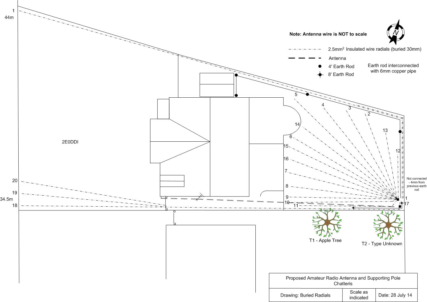
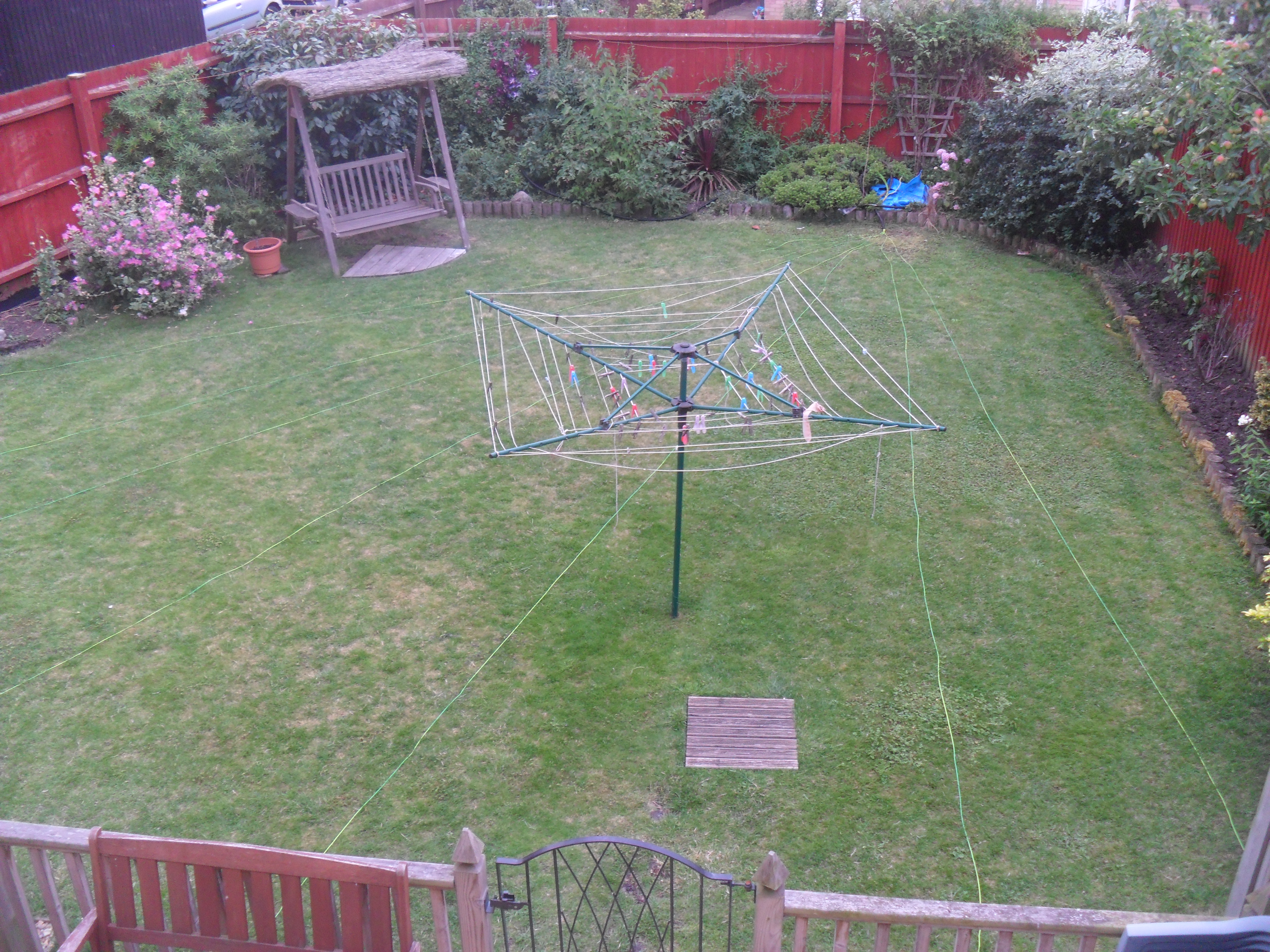
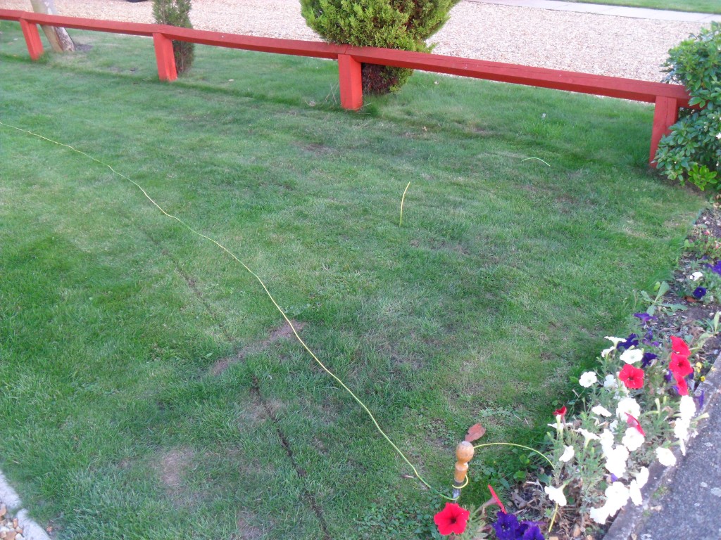
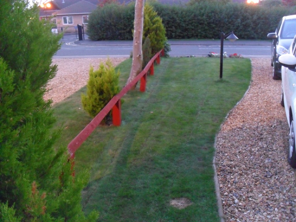
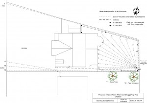
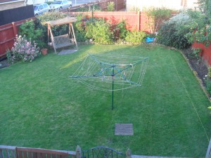
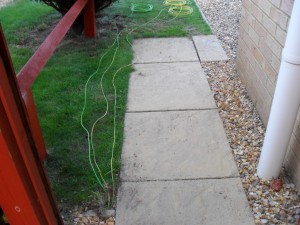
Installation of the radials for my antenna started by laying them out to get the correct spacing, the first lawn picture shows 7 wires, the total in the lawn was 15 in the end, additional radials extend to the front of the house, the SG Tuner guidance says to extend the radial past the length of the antenna, hence the radials on the front lawn, the layout plan shows the dimensions to fit my plot:

11 Farriers Gate_Radials

Wires dry laid ready for cutting in:

initial wires layout

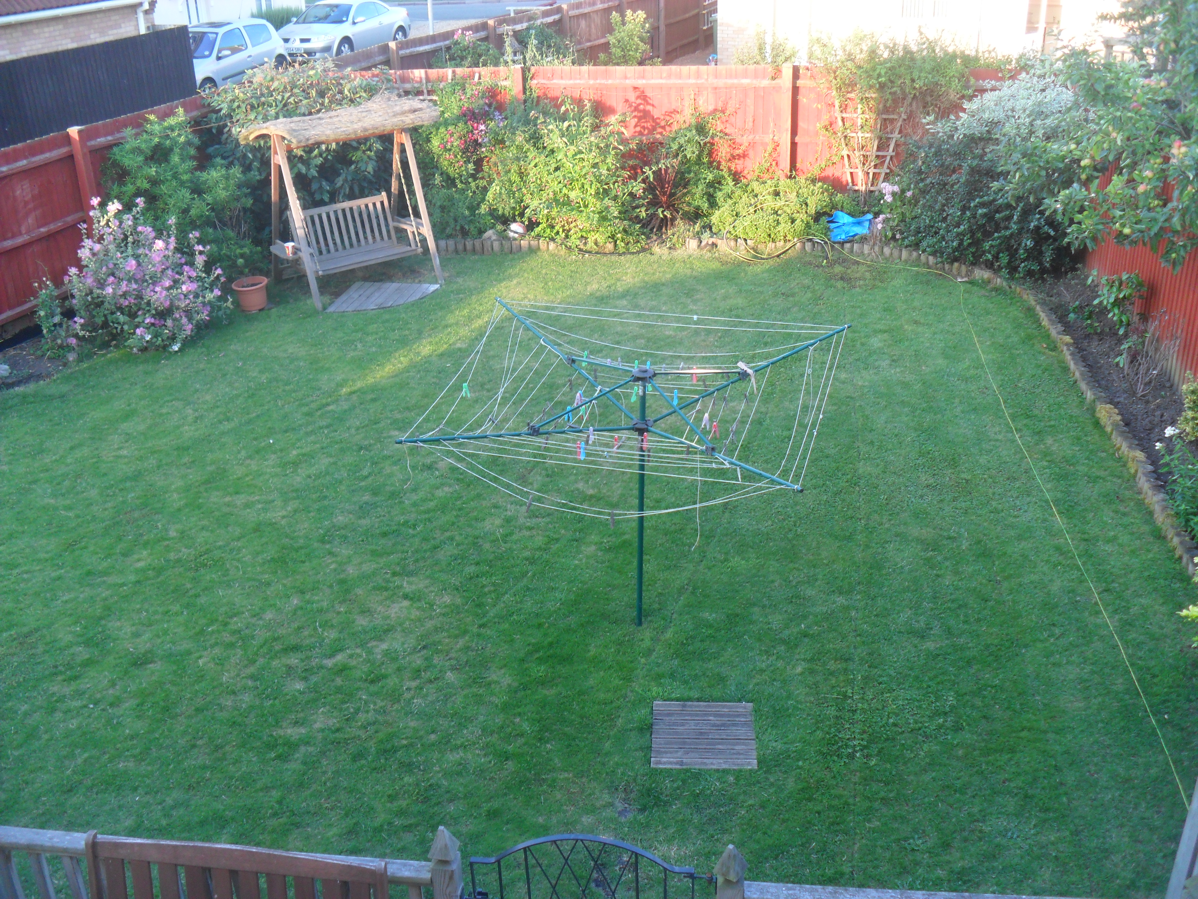
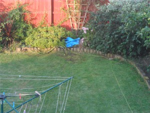
This picture shows the last radial ready for the grass to be cut with the Edging Knife, unfortunately on the start of the last radial the end broke off the shaft!!, time for a trip to Toolstation for a new one (ÂŁ4.80).

buried wires bar 1

The wires will be routed to the base of the antenna tuner in 25mm plastic flexible conduit.

wire out of grass

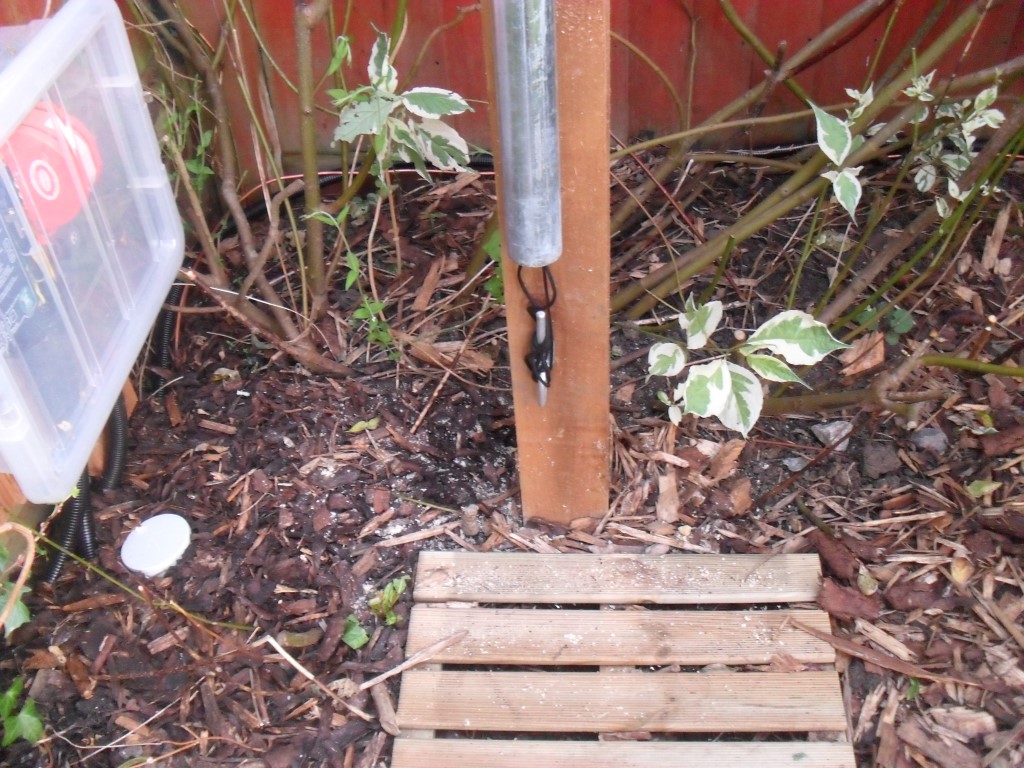
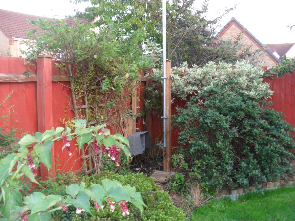
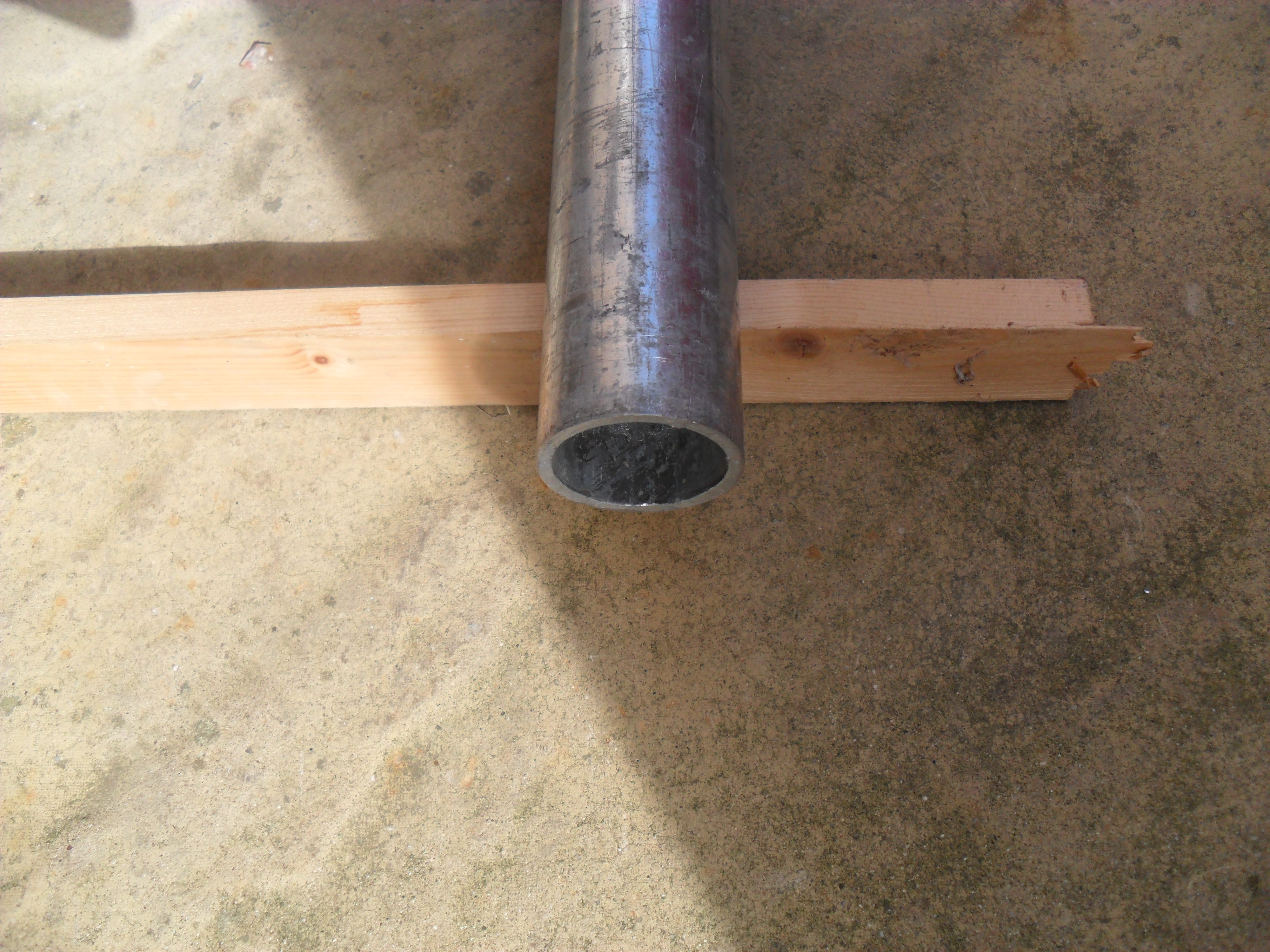
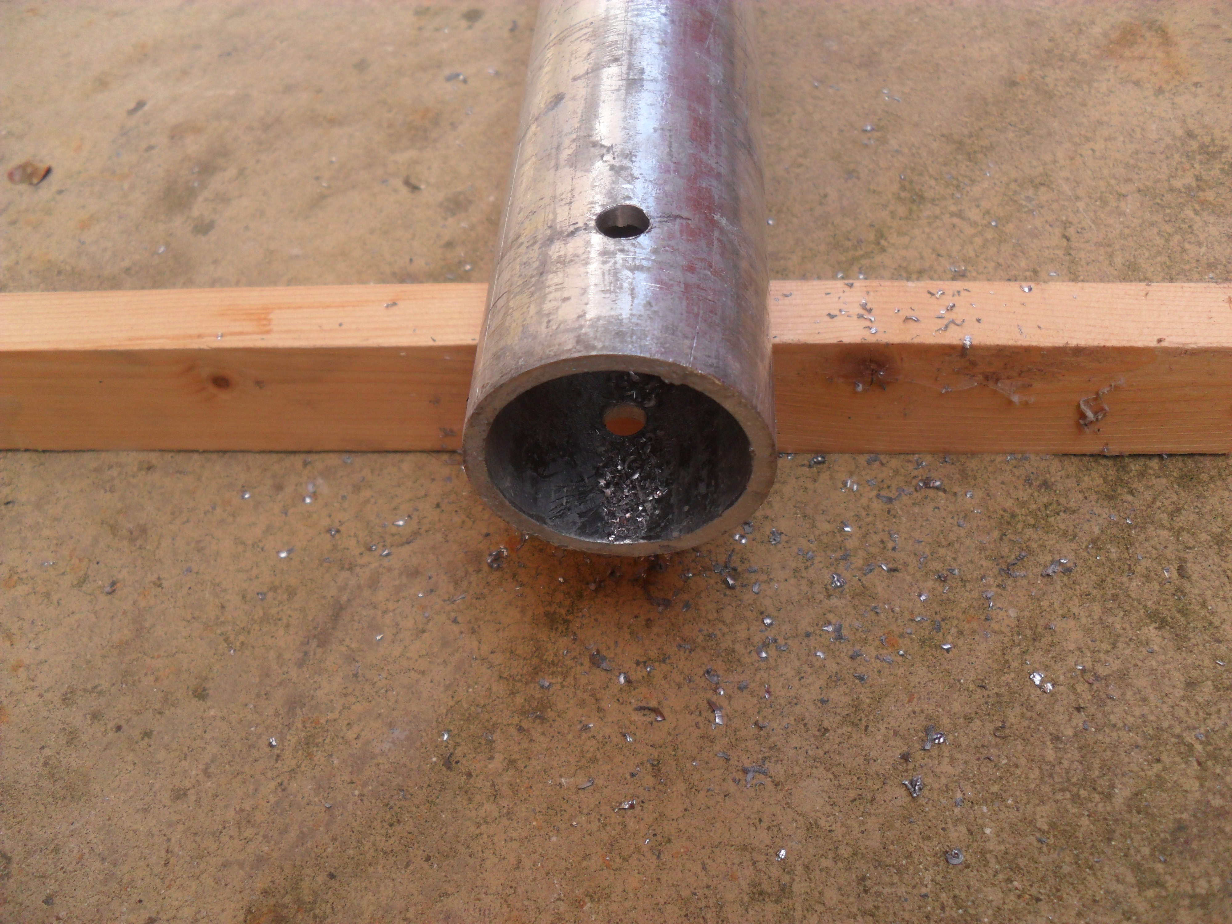
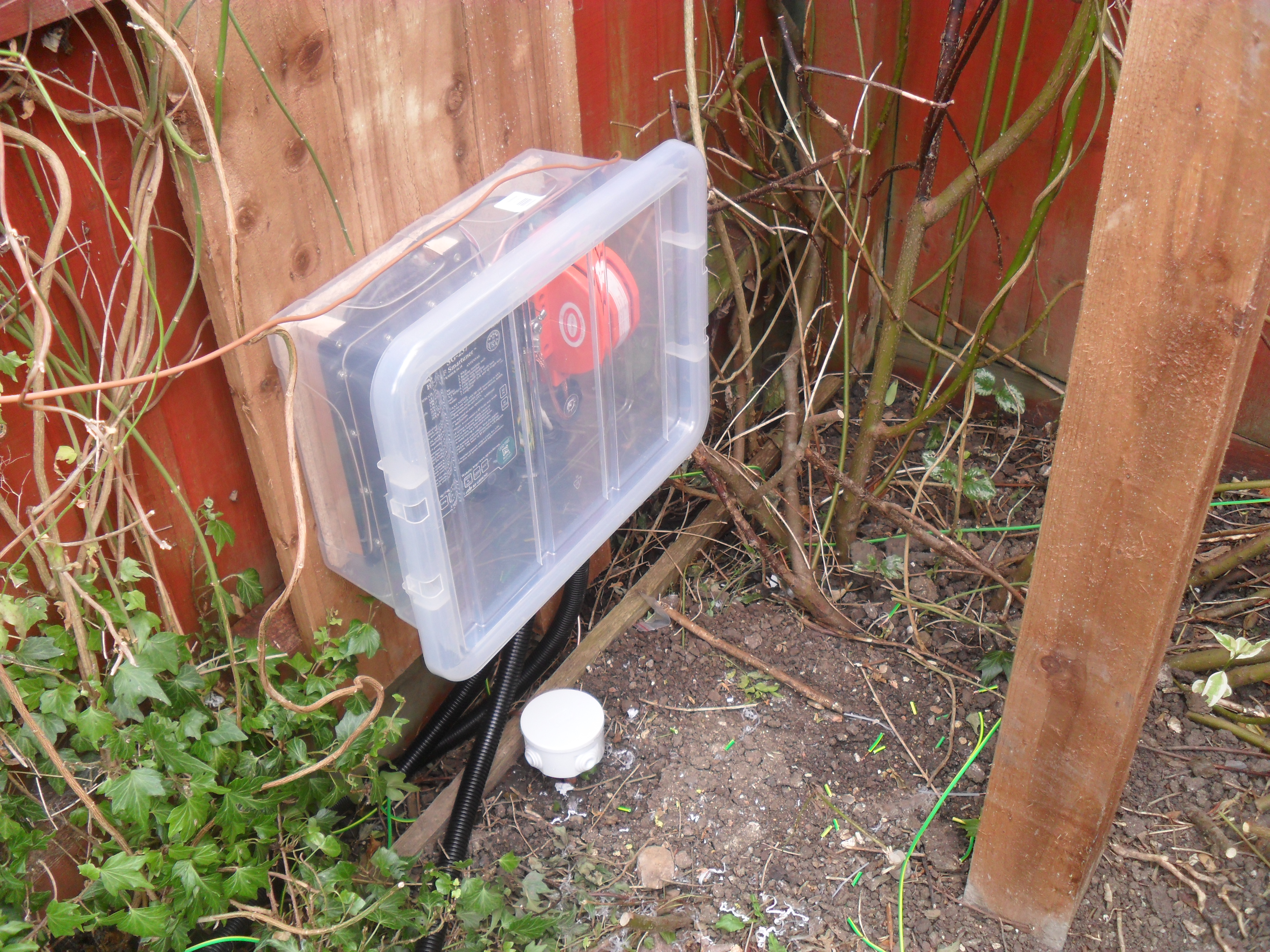
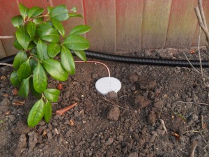
Picture shows the 100mm x 100mm timber post concreted in place which will be used to support the 6m scaffold pole, also in the picture is the circular box where one of the 2.4m copper DC earth terminates and of course the box containing the tuner.

Side tuner boxed

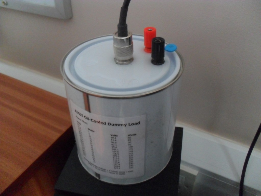
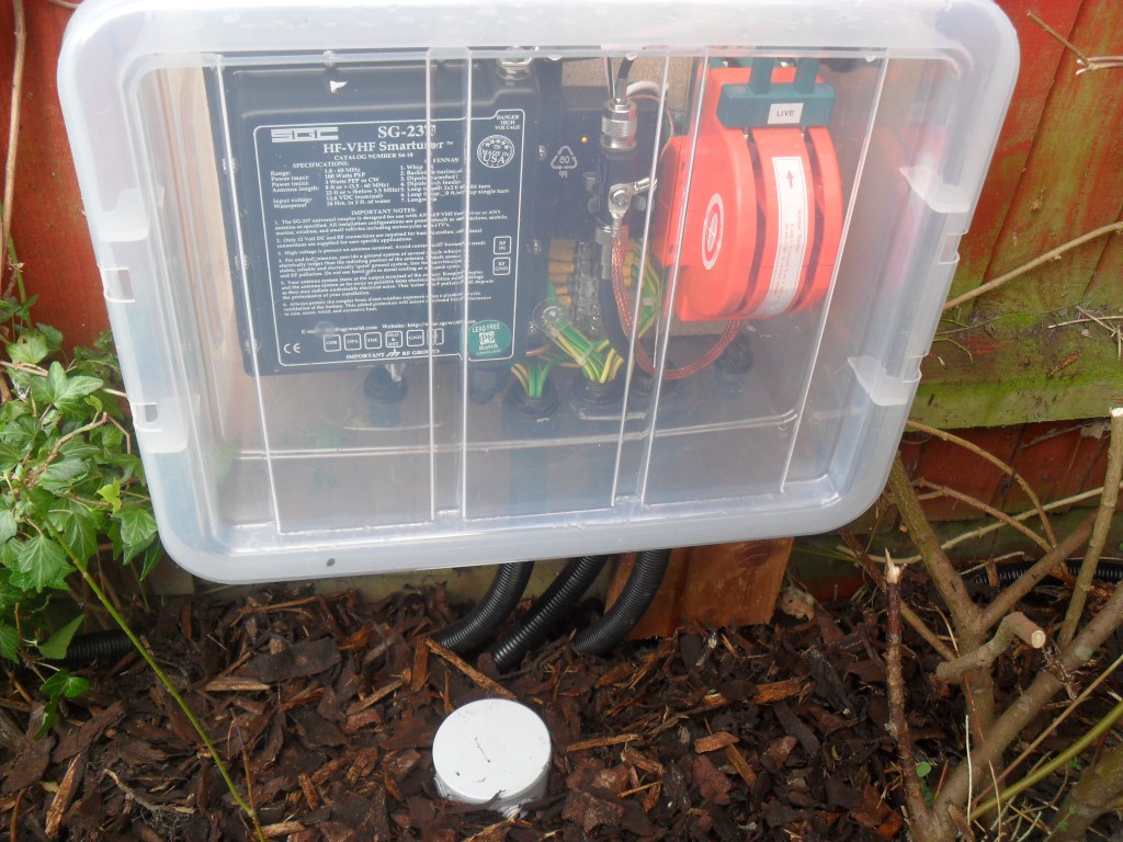
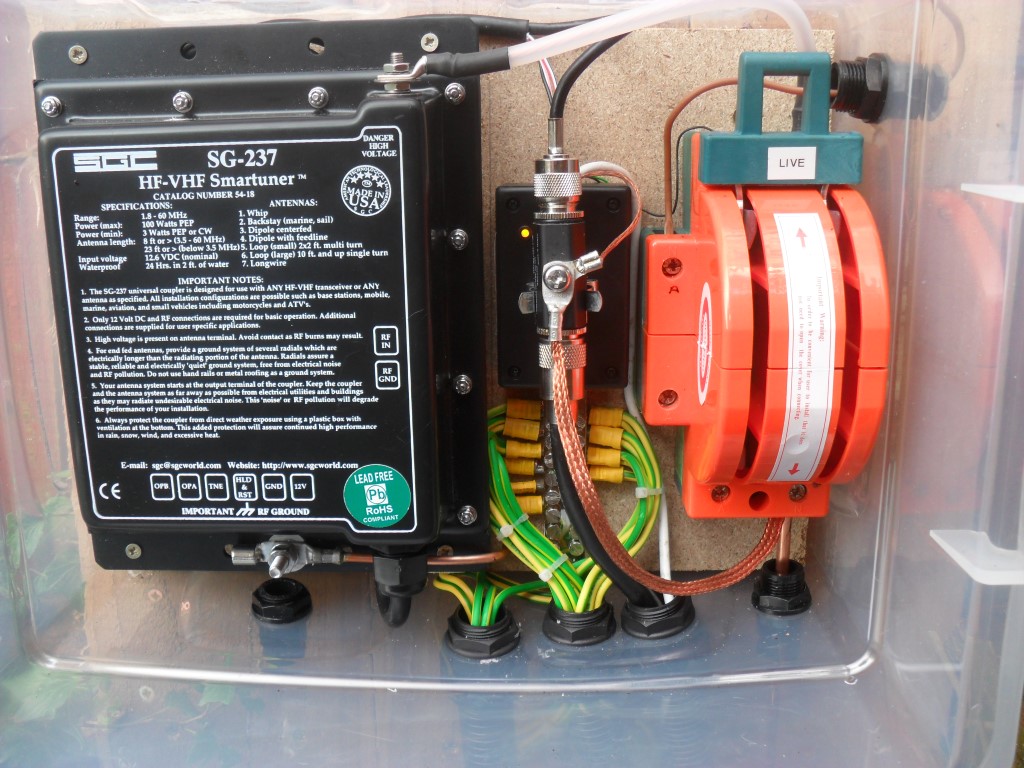
This is the front view of the SG Tuner enclosure, I have used a storage container to keep the elements off the equipment, the location gets very little direct sunlight, hopefully the container is sufficiently UV robust.

SAM_5086 (Medium)

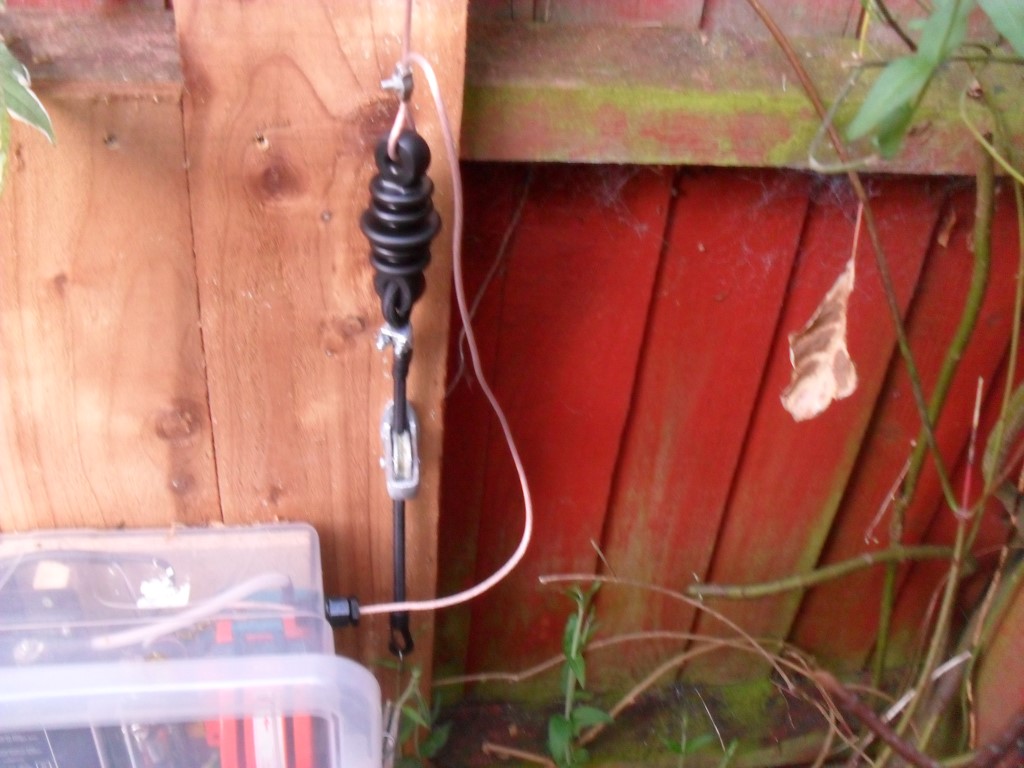
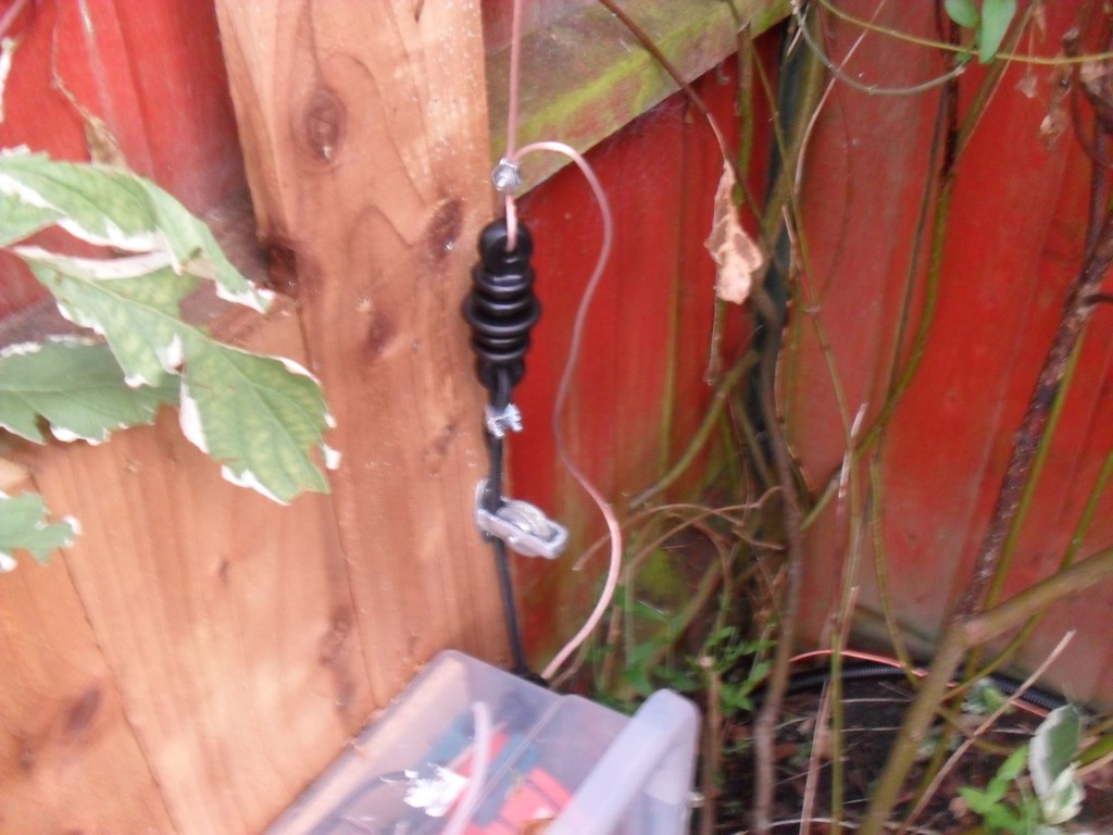
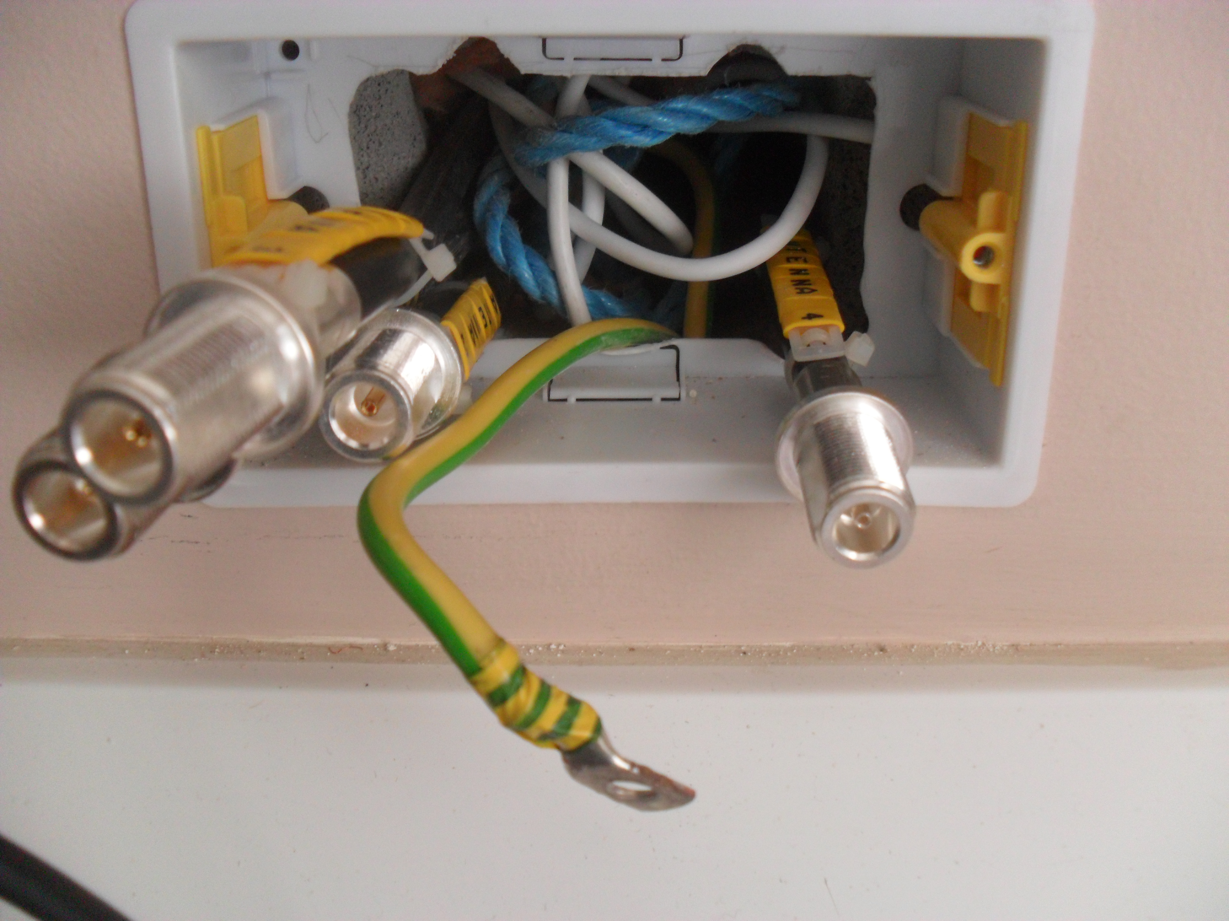
I have raised the tuner off the backboard so that the surplus cable can be neatly coiled behind it, in the centre on the picture is a lightning arrestor held in place with a ‘Terry Clip’, the box the clip is mounted to is for the low voltage connections to the home made Smart-Tuner.

SAM_5087 (Medium)

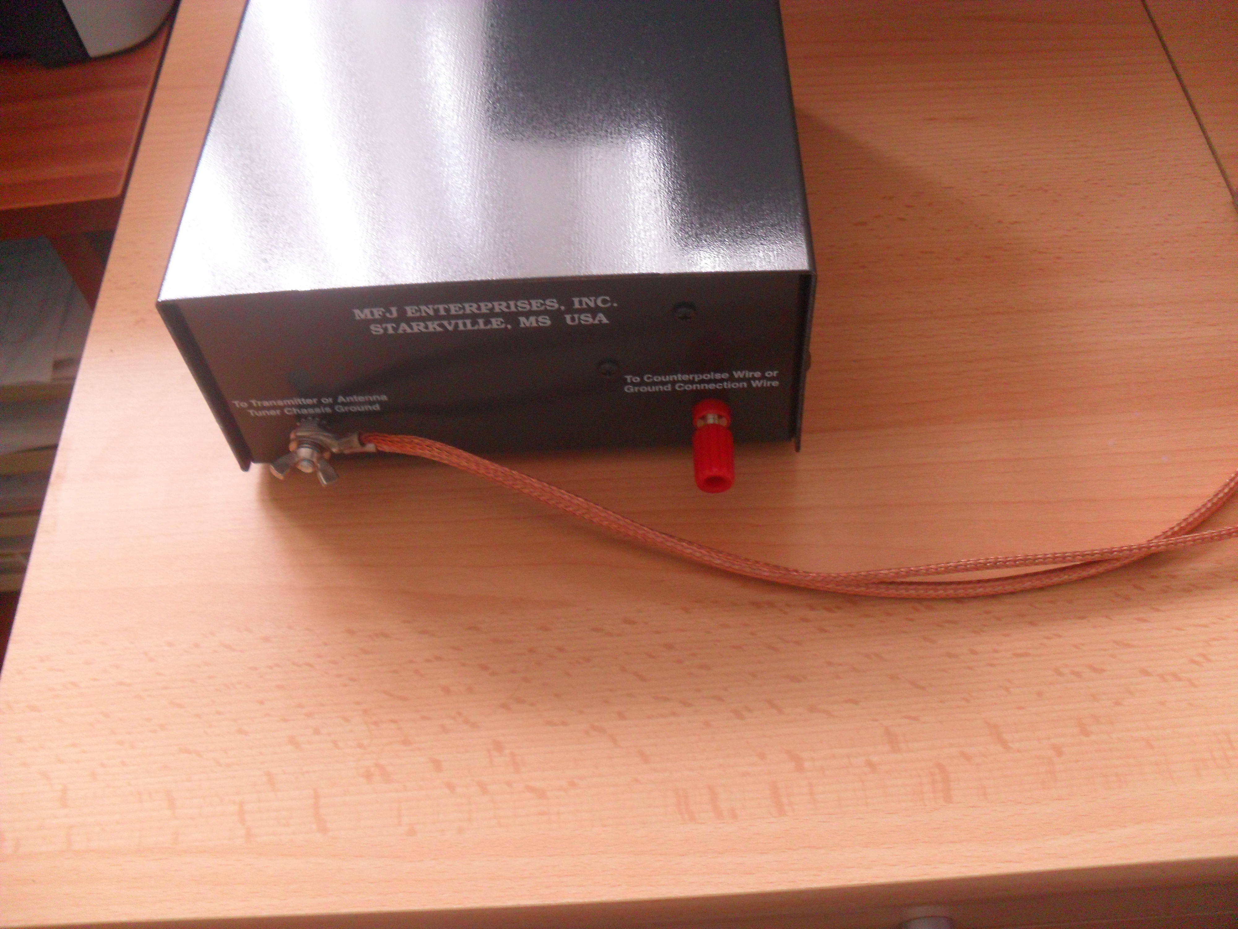
The Amber led indicates power is available as it is fed remotely, the large orange knife switch is set to the working position, one set of blades close a circuit giving me an indication in the shack that the aerial is available, the other set of blades either routes the longwire (when fitted) to the tuner or to ground.

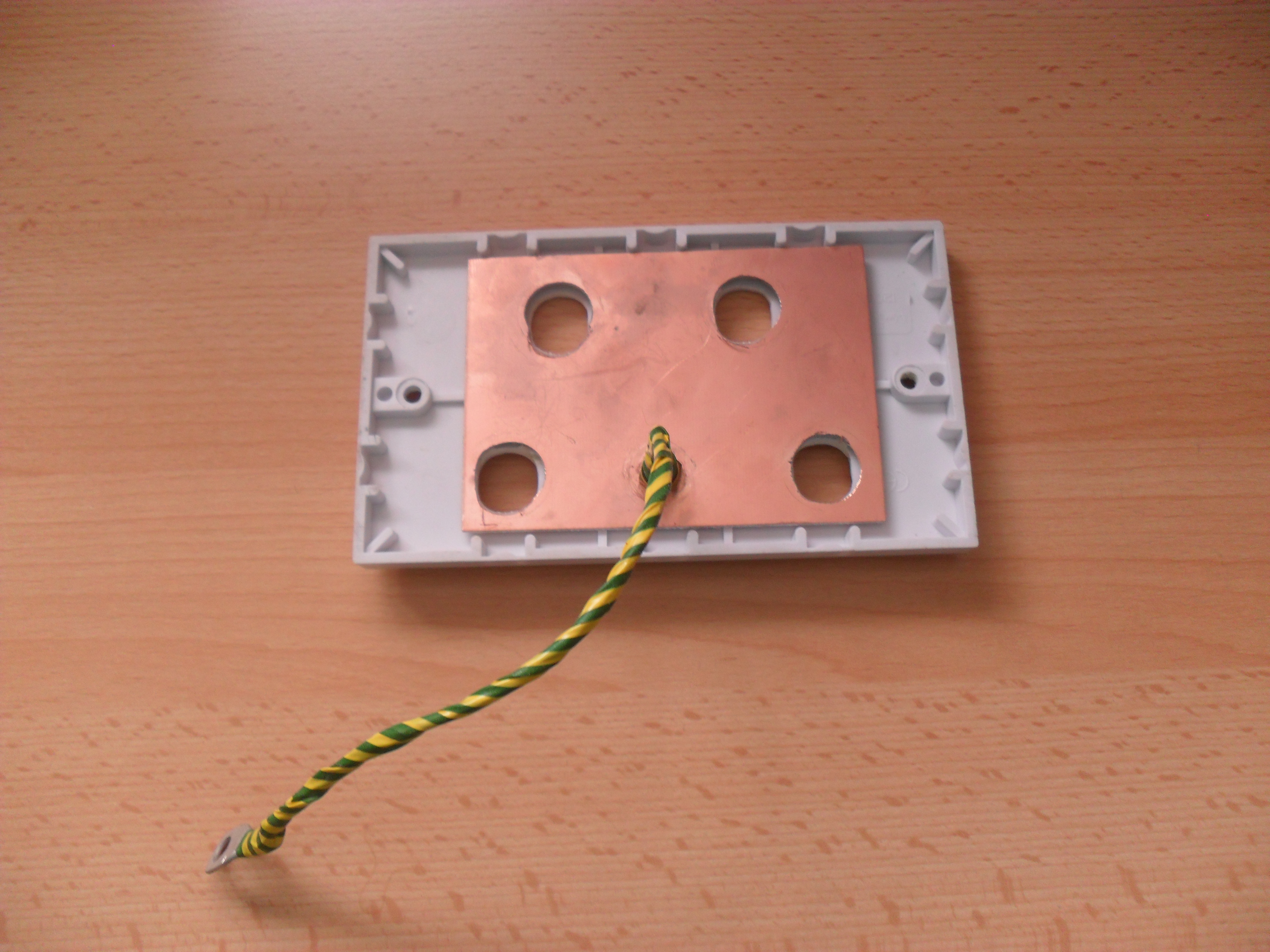
The earth block brings in the ground radials, I have used 20 with an overall distance of 400m.

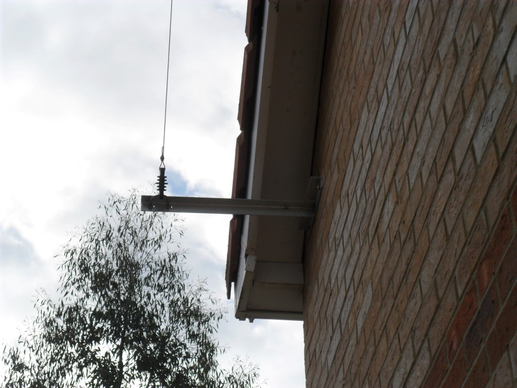
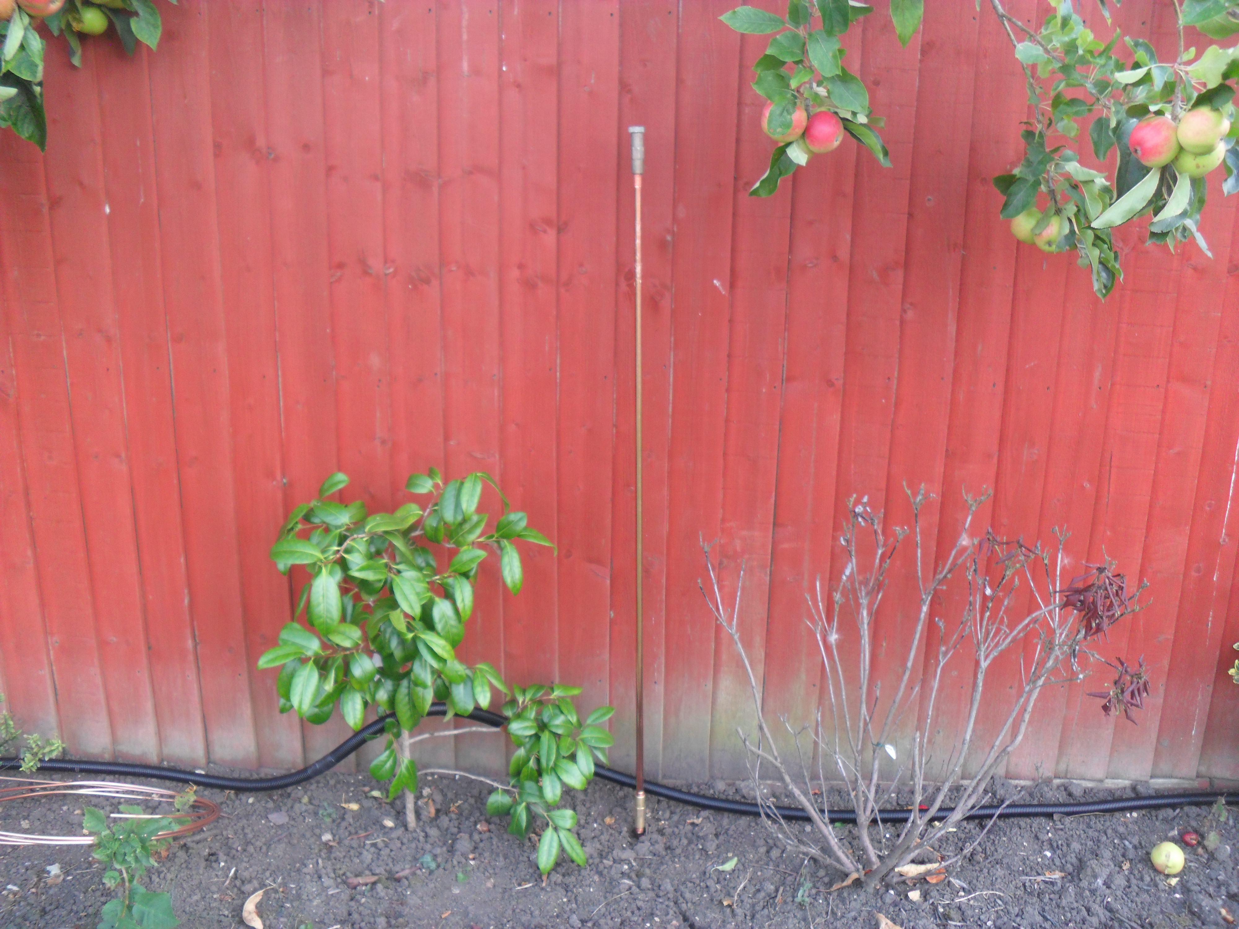
I have separate earth rods for RF and Lightning, each of the lightning rods is a total of 2.4m long (two 1.2m coupled together as picture), rods are spaced 9m apart from each other, the construction of the rod is 15mm copper coated steel.

This picture shows that one rod has been driven in, with the additional 1.2m rod coupled to it, ready to be hammered in. On the top of the rod is another coupling and bolt which takes the impact of the hammer, it is simply unscrewed when finished leaving the top of the rod undamaged.

SAM_5092

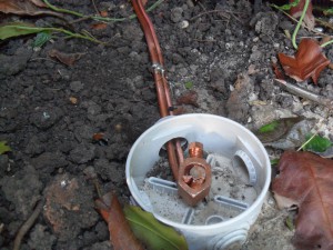
Once level with the ground, a Gweiss round box is used to identify and protect the connection to the rod, I have used 10mm diameter copper pipe as the conductor, this will be buried once all the other cables are in place.

SAM_5094

The RF earth uses 1.2m x 10mm copper coated steel earth rods, 4 have been used, each spaced at 5m from each other, interconnection is by 10mm copper pipe, where the connection ‘loops through’, I have soldered the two pipes together for extra measure.

The smaller diameter rods do not have threaded ends to allow extensions in length, the tip is to place the cable clamp over the rod before you start hammering, as the head of the rod will ‘pan’ over, which might make it difficult depending which type of clamp you use.

SAM_5090

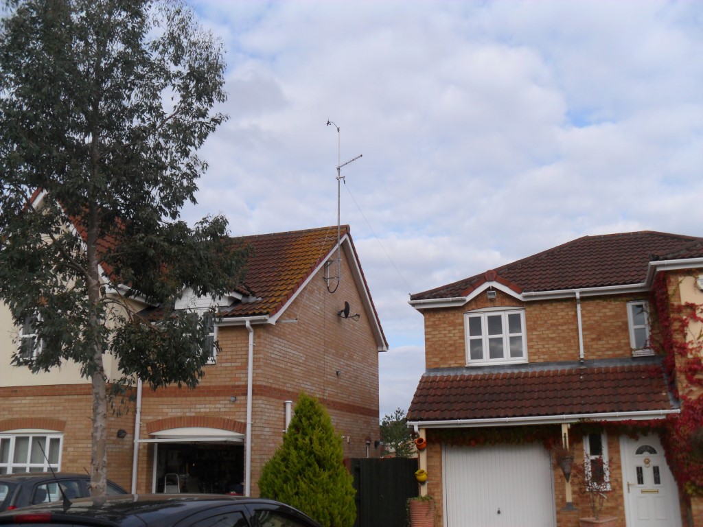
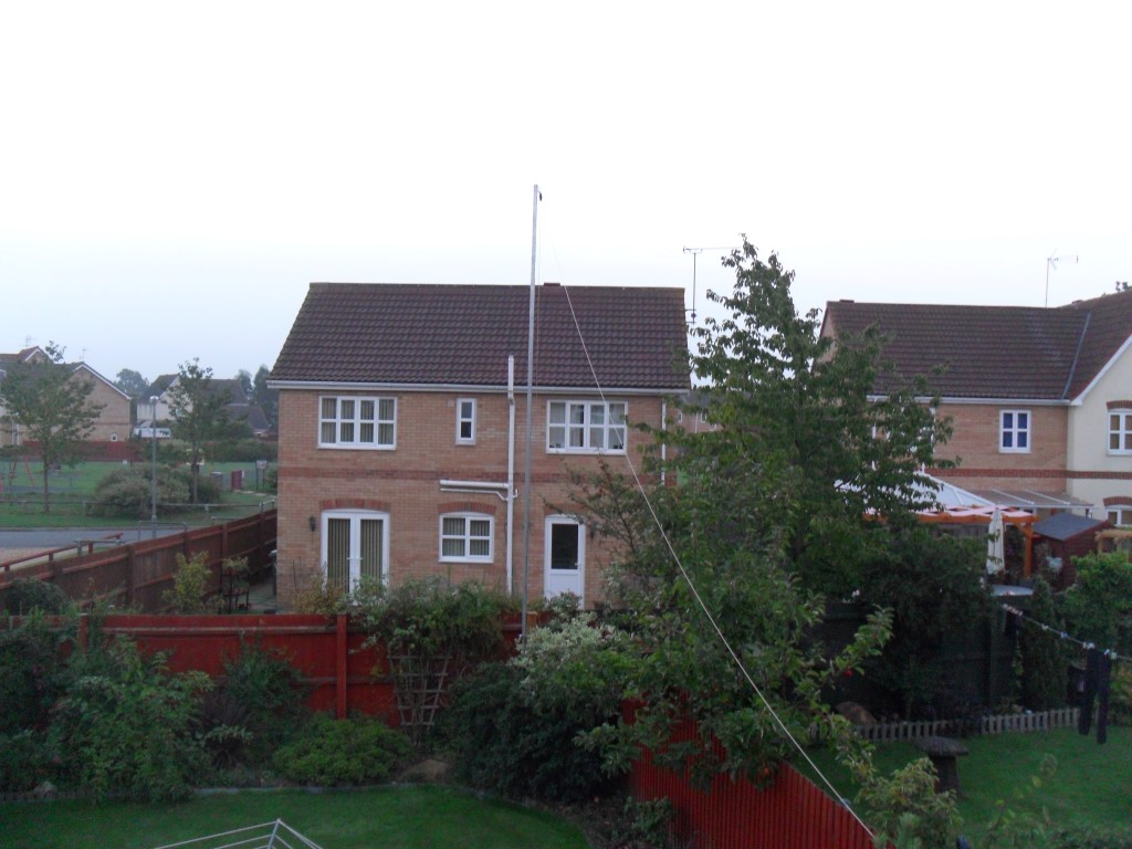
Planning permission application is now in the public domain (8th August 14) on www.fenland.gov.uk for the aerial wire and support post, hopefully the next installment will show this fitted with pictures.

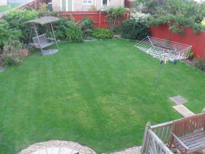
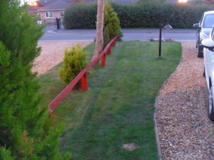
Picture taken on the 17th August 14 showing the new galvanized lawn edgings and lawn seeded, the radial lawn cuts have almost disappeared and the garden is looking ok, the lawn edging is also connected to the radials to maximize the RF Earth from the Tuner.

seeded

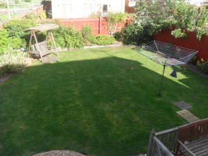
2 weeks after seeding and feeding, the lawn is not looking too bad.

2014-09-06 19.55.05 (Medium)

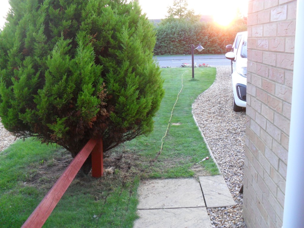
9th August 14, Finished laying the front of house radials, the photos show progress:

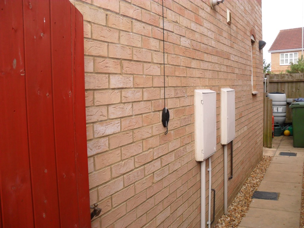
Wires layed under the gravel down the side of the house before breaking out to the front lawn.

SAM_5153 (Medium)

Last of the three wires ready for the edging knife to be cut in.

SAM_5156 (Medium)

Wire ready to be pushed into the notch, two other wires are sticking out ready to have an insulating crimp fitted.

SAM_5157 (Medium)

Wires in and gone.

SAM_5159 (Medium)

Click for part 3
 

July 14 update on getting on air progress

Thought I’d do a quick update on how I’m progressing with my shack equipment and any changes I’ve made since my last blog.

I have done a fair bit of reading on the subject of RF Grounding, as opposed to safety earthing, where the shack is on the first floor as is mine, the issue is the 4m grounding cable which goes to the earth rods, dependent on this cables length being a derivative of a particular wavelength, it may act as an additional antenna and radiate, especially with my proposal of using an end fed antenna which is unbalanced.

To be honest it seems like a black art, so to avoid any problems I may have gone over the top, but better that, than problems later on, so what have I done.

First job was to purchase a MFJ-931 Artificial Ground, this unit allows the cable to the ground rods to be tuned out of being a radiating element returning it to a relatively effective path for RF currents to drive against. I will be installing more earth rods local to the SCG Tuner as well as installing counterpoise wires, but that is for another blog :-).

The MFJ-931 is on top of the MFJ-949E tuner.

Shack setup

The rear of the Artificial Earth has two terminals, the wing nut one is to bring in the grounds from the rig and ancillary equipment, in my case it’s simply the Rig and the antenna tuner, the picture below shows the rear of the MFJ-931 with the two copper braided leads crimped up ready for the incoming connection.

Ground copper braid

I had to modify the antenna connector wall bulkhead for the artificial earth to be effective as the original faceplate design earthed the incoming connectors via a copper plate with an earth stud which made contact with it, the modification involved removing the bolt and replacing it with an insulated banana plug socket, the connection to the existing 10mm2 cable was by using copper braid, again insulated so as to keep the grounding point to be the MFJ-931.

Incomming Antenna bonding bulkhead insulated from the RF Earth

One change I made from the original antenna faceplate installation was to change the metal back box to a plastic dry ling type, this allows me to easily remove the box giving greater access. So I can dismantle the faceplate, I replaced the soldered SO259 sockets with crimped ‘N’ Type bulkhead ones and it has made a huge difference as I’m not constrained by cable length when I remove the faceplate.

Antenna drylining box

This is the antenna faceplate back in place.

Assembled antenna faceplate

I will know in the next few weeks whether or not this has been worth it when the external antenna goes up and I start transmitting, my license limits me to 50watts at the antenna, so it may well be that no problems are apparent until I start transmitting at a value greater than this in the future.

Neat Feature of Ham Radio Deluxe

I recently installed Ham Radio Deluxe software, this software allows remote control of my rig as well as a whole host of other functions and features, working through these I stumbled across a neat little feature, that is the ability to automatically post to your web site details of the frequency, mode and time last seen using the rig at regular intervals, I retained the default of every 5 minutes.

An example of the output can be seen here on my site.

Setup is fairly straightforward, the main details you must have are your host upload details and password, I use Notepad++ to edit and create pages, using this I added the following text and saved as radio.html:

2E0DDI was last seen on frequency ###-frequency-###MHz using ###-mode-### mode with a Kenwood ###-radio-### Multi Band Transceiver at ###-timestamp-### – Data automatically updates every 5 minutes when using Ham Radio Deluxe Software.

Once Ham Radio Deluxe is downloaded and the connection and control is established with the radio, go to Tools >> Web Page Updates.

In this panel, enter the location of the html document previously created, your host name, directory you want to upload the document to, (I simply placed it in the root directory – /web), fill in your user id and password, then press the test upload button, if all is well, the detail box will show success, if transfer fails, re-check your settings.

Hopefully your still with me :-), so the next bit is to insert the information which is being uploaded into your web page, the raw information looks like this on my site.

Where you want this to display, add this to the page using iframes –

iframe src=”http://www.your web site/radio.html” frameborder=”0″ width=”700″ height=”75″>/iframe>

In order to show the code I had to remove the < from in front of the first iframe and also in front of the ending /iframe – place the < back in front for the frame to work, (if I’d left the < in, you would have seen a blank frame in the blog page as the information was trying to be gathered from a non existent source of www. your web site) That’s it, hope you found it useful, the feature does only work when you are working through the Ham Radio Deluxe software, but it is quite a nice addition to your site. When I get my antenna sorted, I will add a contact log to my web site, again this can be automated through this software. 73