
Thought I’d do a quick update on how I’m progressing with my shack equipment and any changes I’ve made since my last blog.
I have done a fair bit of reading on the subject of RF Grounding, as opposed to safety earthing, where the shack is on the first floor as is mine, the issue is the 4m grounding cable which goes to the earth rods, dependent on this cables length being a derivative of a particular wavelength, it may act as an additional antenna and radiate, especially with my proposal of using an end fed antenna which is unbalanced.
To be honest it seems like a black art, so to avoid any problems I may have gone over the top, but better that, than problems later on, so what have I done.
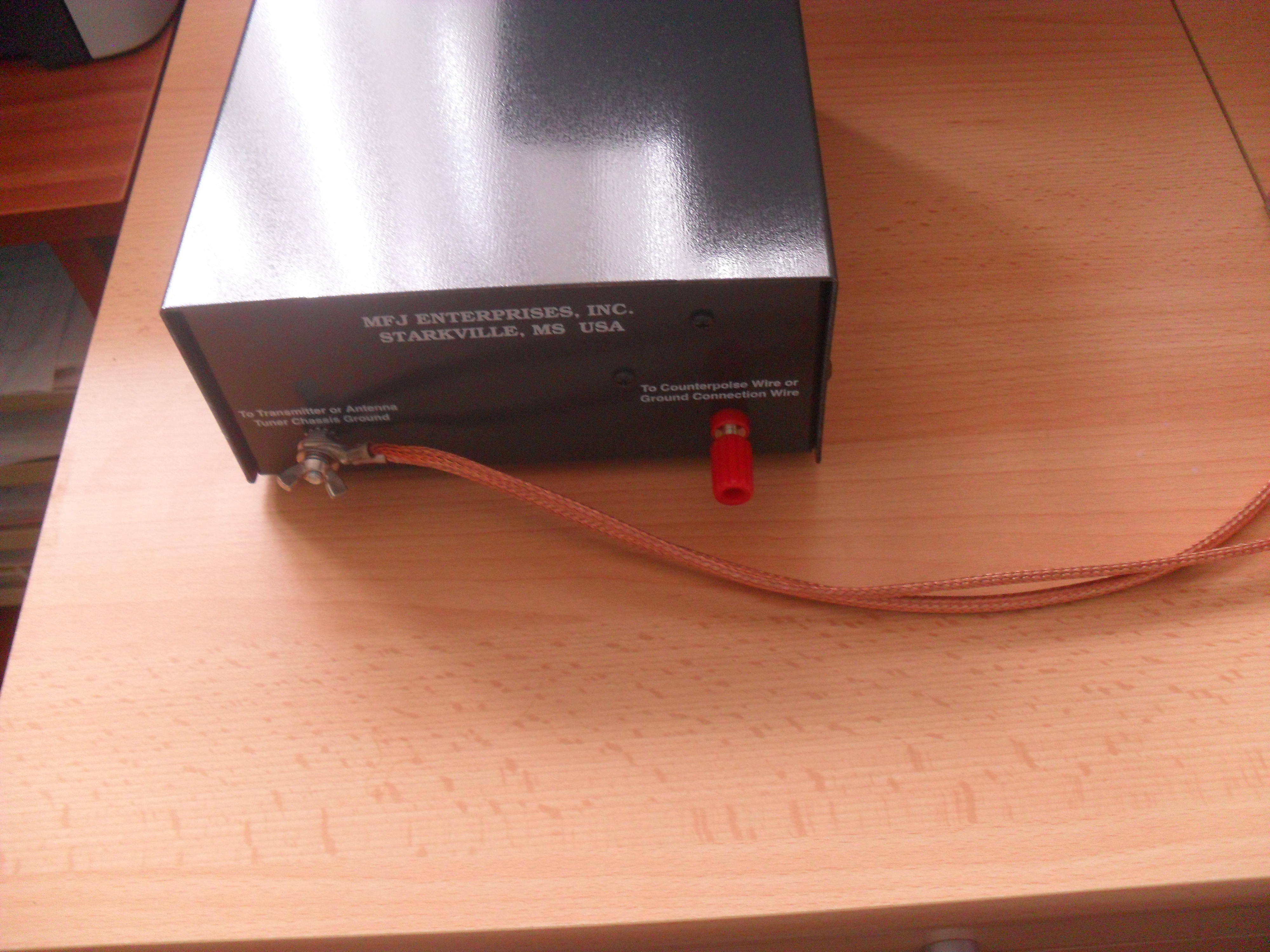
First job was to purchase a MFJ-931 Artificial Ground, this unit allows the cable to the ground rods to be tuned out of being a radiating element returning it to a relatively effective path for RF currents to drive against. I will be installing more earth rods local to the SCG Tuner as well as installing counterpoise wires, but that is for another blog :-).
The MFJ-931 is on top of the MFJ-949E tuner.

The rear of the Artificial Earth has two terminals, the wing nut one is to bring in the grounds from the rig and ancillary equipment, in my case it’s simply the Rig and the antenna tuner, the picture below shows the rear of the MFJ-931 with the two copper braided leads crimped up ready for the incoming connection.
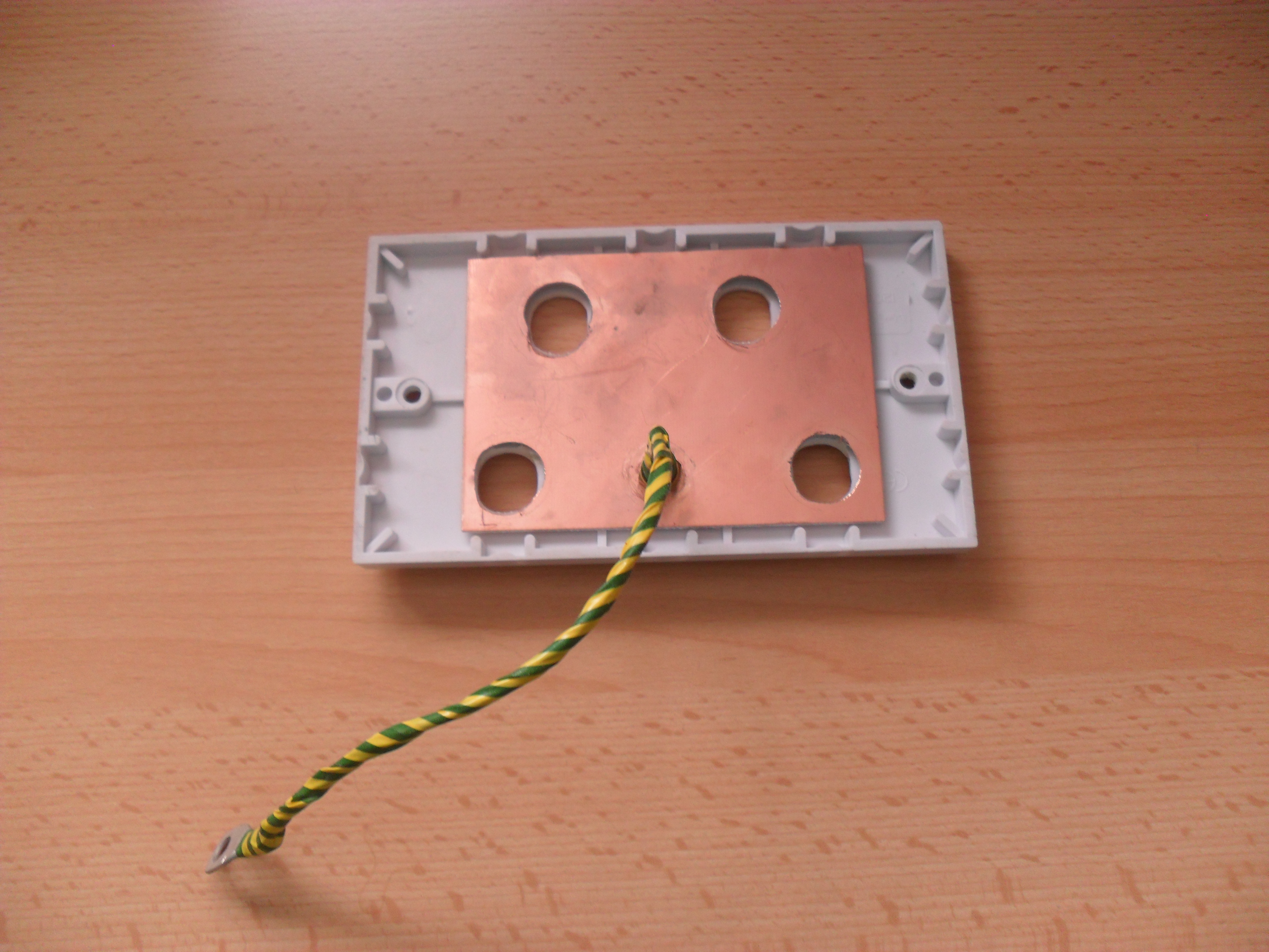
I had to modify the antenna connector wall bulkhead for the artificial earth to be effective as the original faceplate design earthed the incoming connectors via a copper plate with an earth stud which made contact with it, the modification involved removing the bolt and replacing it with an insulated banana plug socket, the connection to the existing 10mm2 cable was by using copper braid, again insulated so as to keep the grounding point to be the MFJ-931.
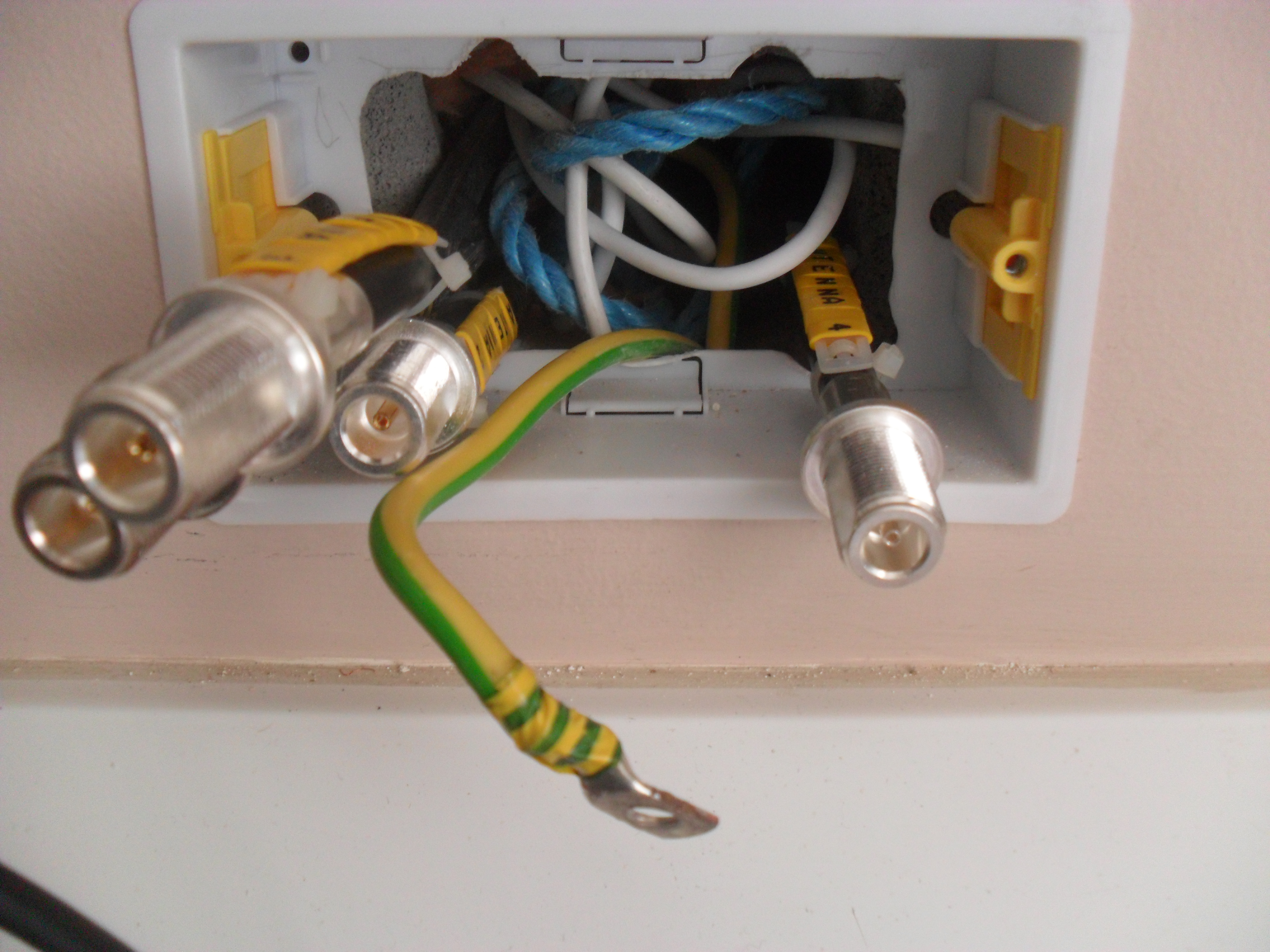
One change I made from the original antenna faceplate installation was to change the metal back box to a plastic dry ling type, this allows me to easily remove the box giving greater access. So I can dismantle the faceplate, I replaced the soldered SO259 sockets with crimped ‘N’ Type bulkhead ones and it has made a huge difference as I’m not constrained by cable length when I remove the faceplate.
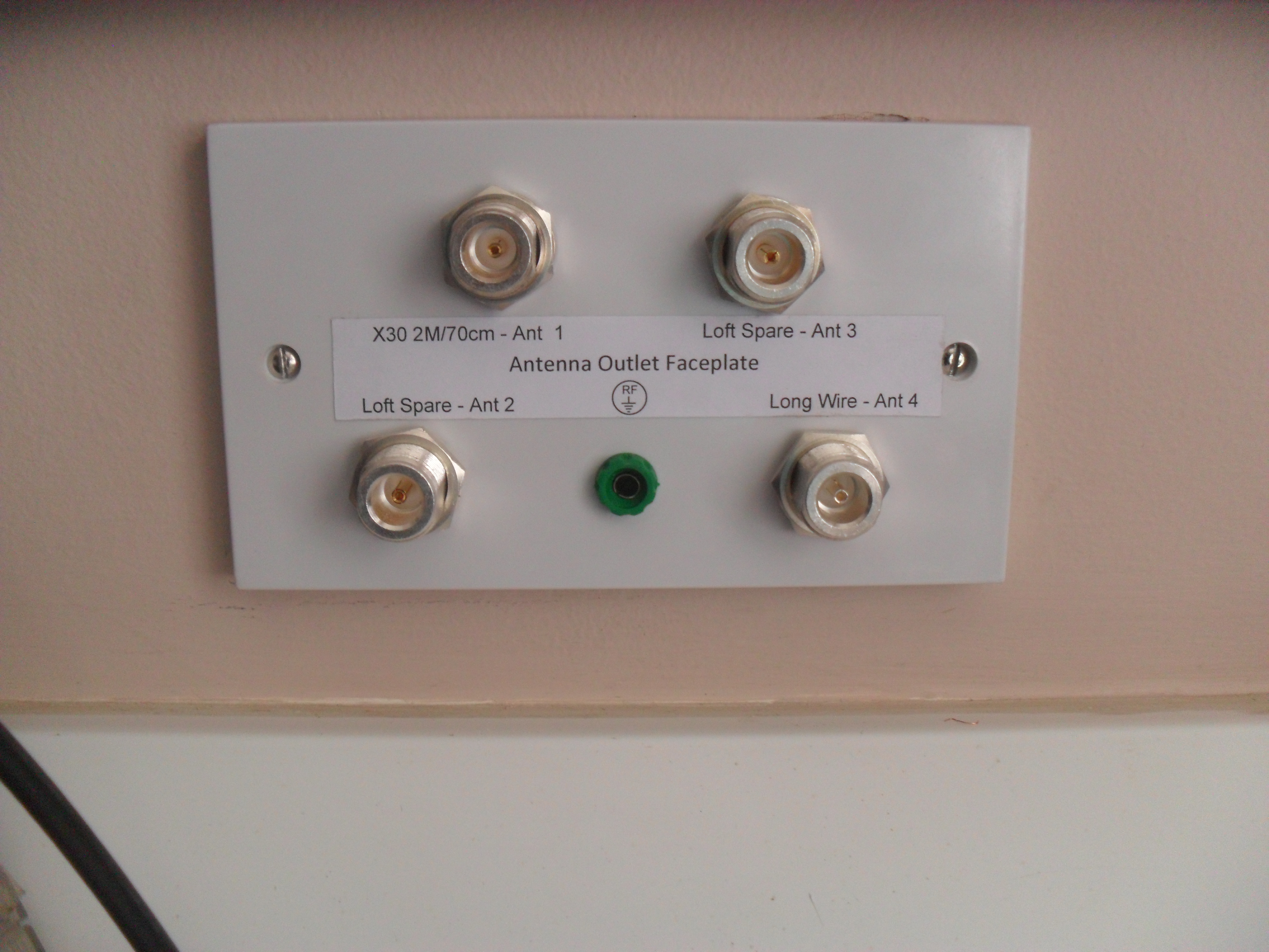
This is the antenna faceplate back in place.
I will know in the next few weeks whether or not this has been worth it when the external antenna goes up and I start transmitting, my license limits me to 50watts at the antenna, so it may well be that no problems are apparent until I start transmitting at a value greater than this in the future.