Not sure where to start with this, so the easiest first; I enjoy listening to the scheduled networks on FM, and as a member of CDARC I wanted to participate in their regular nets, unfortunately my Diamond X30 just could not quite pull in all the signals (Chatteris is not exactly the (highest point on the planet – not the lowest though!).
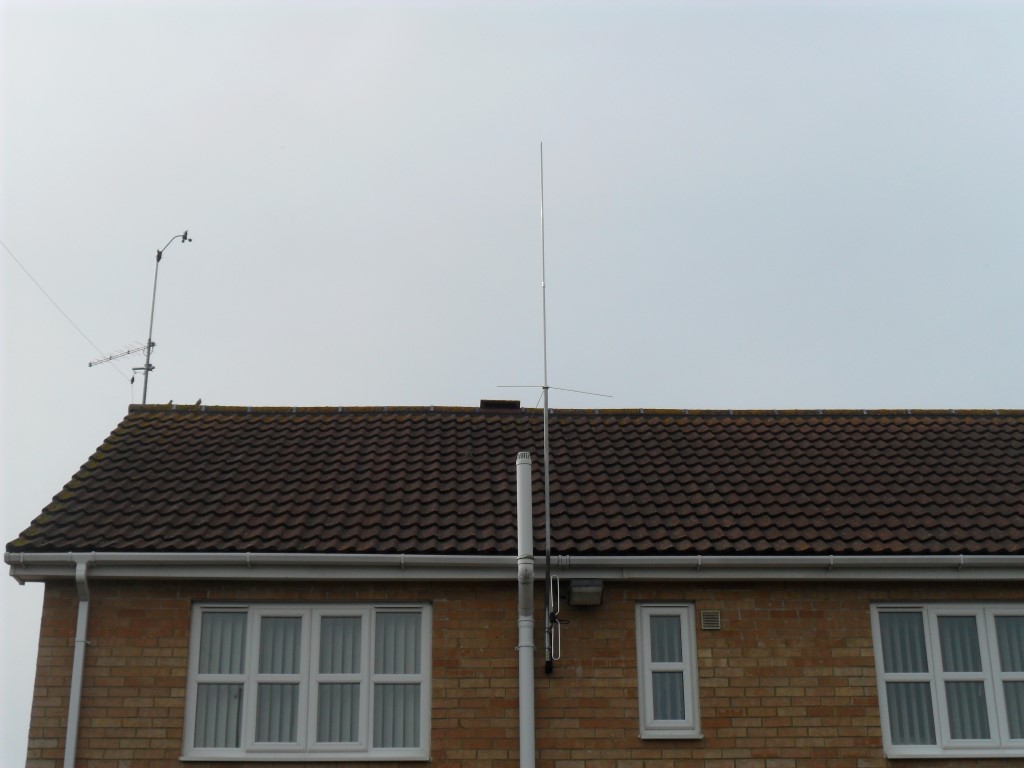
I opted for the SPA-X200-N from an ebay vendor due to the increase in gain, ability to be a direct replacement for the X30 and its price point. I tested the antenna for the first time today (12 Oct 14) and worked really well, this antenna is not a Diamond original so hopefully it will last, I have used silicon grease on the sealing gasket where the two sections screw together to keep the water out but I suppose that’s not much use if it snaps in the wind 🙁 -Watch this space!
 X200 which replaced the smaller X30
The X200 is connected to a coaxial switching relay in the loft, as my intention to remotely switch over to a dual band Yagi antenna for listening/transmitting on sideband, but that’s for another time.
Ok, the next saga was my lack of reception when using my random length antenna, the antenna would tune but the transceiver was quiet of activity, called Andy (G6OHM) for his advice and whist we were on the phone compared what he could receive on a particular frequency to me when tuned to the same frequency, yep something wasn’t right.
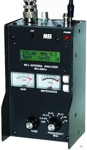
Andy came round armed with his experience and a 4:1 balun, right he said “back to basics”, so the SG auto-tuner, MFJ artificial ground unit and MFJ SWR/tuner came out of circuit and the balun went in, simply connected to the antenna wire and earth, their was a huge difference, but Andy noticed the really high background noise level causing signals to struggle to be heard, I was pleased that the signals had been increased, but a bit miffed that all this quite expensive kit was redundant, Andy loaned me the balun, and that night I ordered one from ebay for £33.00.
A few days later I decided to power the rig from a battery and turn the house power off to try and locate the source of the background interference, it turned out that the biggest problem started around 29.700Mhz where S+60db signal noise is noted, I suspect is from a neighbours solar power inverter, outside of this frequency the background noise wasn’t that noticeable.
I relocated the rigs Power Supply to beneath the desk and started turning the power on, one circuit at a time, each time checking the radio for additional interference, I was hoping for a dramatic leap in background noise caused by electrical interference, but the background noise didn’t really alter which was strange, when Andy was here a few days earlier it did have a higher noise floor.
I have previously spent a lot of effort putting in a ground earth system, so I though I’d measure the resistance from the cable outer at the garden end to my earth terminal block which is robustly connected throughout back to the rig, when I saw the reading was into fluctuating Megohms rather than ohms, I thought ‘now that can’t be right’?????!
From the earth block at the bottom of the garden I ran a connected wandering lead with a multimeter inline set on ohms scale to track the where the problem was, at each of the earth rod positions measured the resistance of the copper earth rod connection back to the earth block (taking into account the additional resistance the wandering lead introduced), all read less that 1 ohm, that is until I measured the last one before it enters the house on route to the rig, where it was all over the place, it turned out that the brass bolt which secured the earth clamp to the copper rod had failed and the earthing connections had sprung open. Inspecting the bolt showed that the brass casting in the center of the bolt was flawed and the subsequent material stresses had caused a catastrophic failure.
Replacing the bolt and getting the integrity of the RF earth back to the rig and antenna tuner allowed me to put the SG tuner back in circuit and everything seems to be working and receiving just fine.
I have left the MFJ kit disconnected, hence the before and after pictures below:
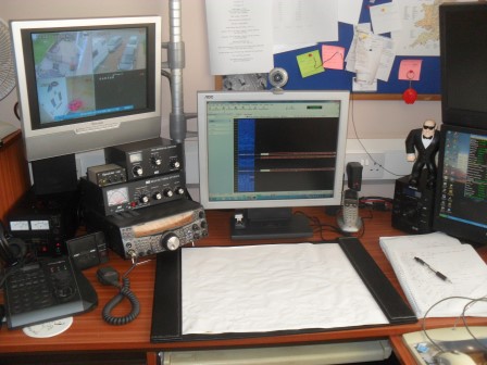
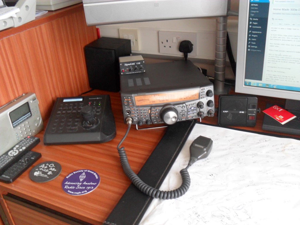
 As was.
 As is (can you spot the difference).
Hindsight moment – Don’t over-read looking for resolution to problems which you haven’t met or experienced yet, more importantly, don’t buy equipment until you know you need it, I also bought a tuner with a built in power and SWR meter, the rig has this already built in, hence it’s now in a box in the loft.
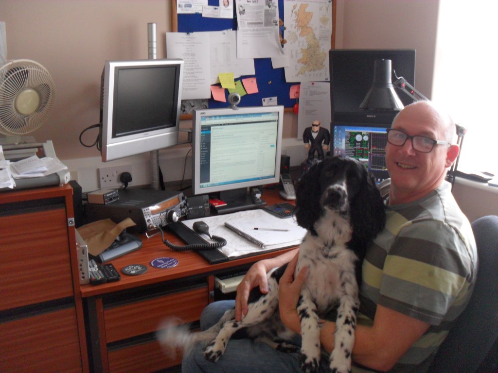
On a lighter note – Here’s me and Barney in the man cave.


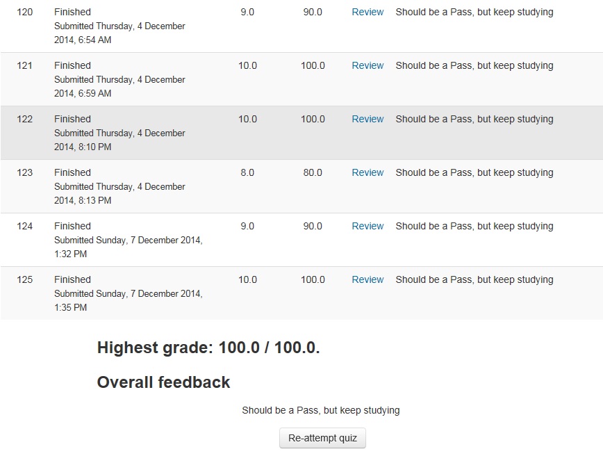 Set of 10 test questions with a 10 minute time limit.
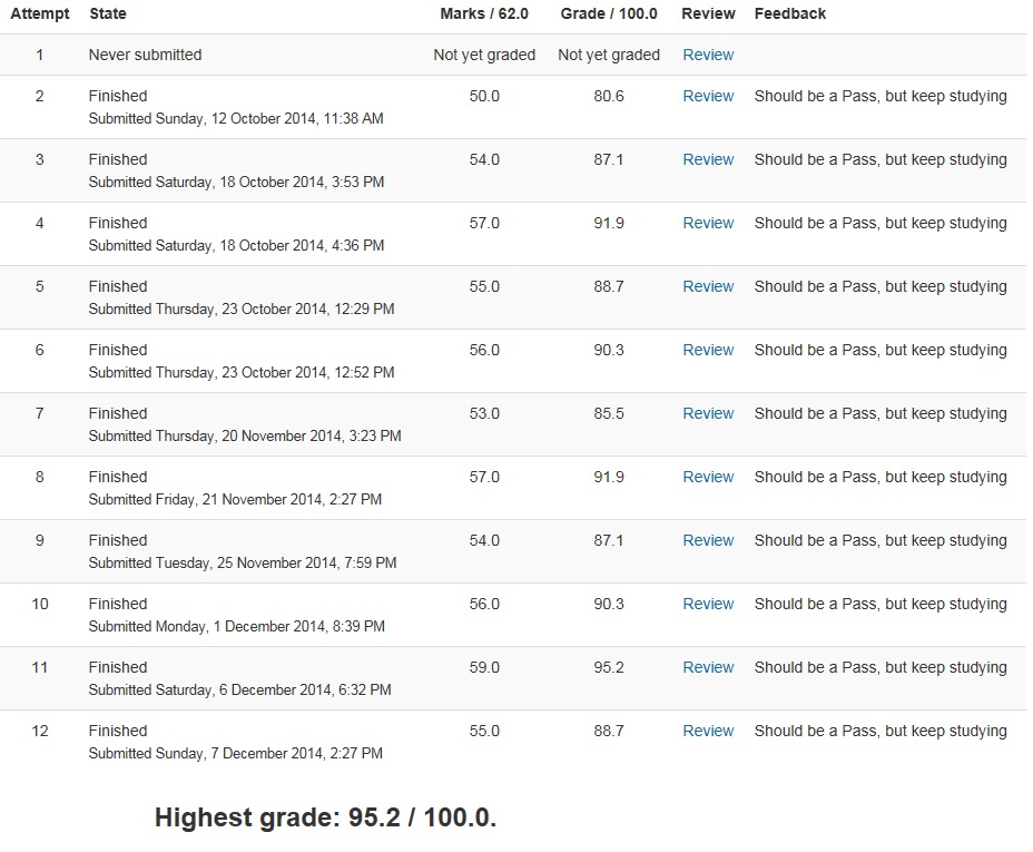 Set of 62 test questions with a 2 hour time limit.
  Combined results of QADV.