
This is Part 2 from this previous thread, the remaining parts have arrived so I could complete the circuit which (hopefully) will give a relatively accurate positional indication, the circuit uses two LM3914 (one for Pan the other Tilt) with a potential divider signal being derived from the potentiometers (Pots) within the Pan/Tilt head, I have mounted the reference resistors slightly proud of the Veroboard as I’m not convinced that the values are correct, so I will be able to modify these from the top of the Veroboard.
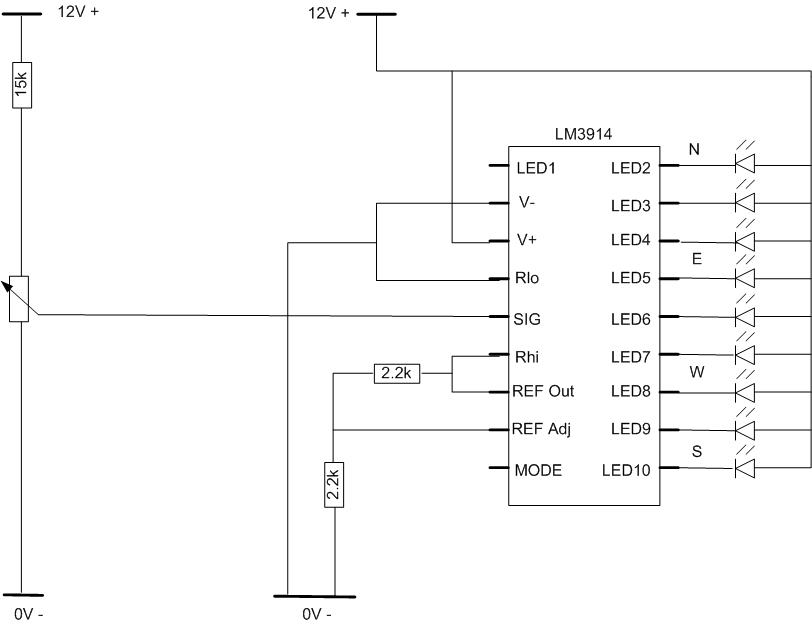
Circuit diagram of positional indication for the Pan element, for Tilt I have used three LEDs and so the wires from each LED will go to the appropriate leg of the IC which has the correct voltage when aligned to the correct position, a mod to make is to convert the mode of the LM3914, so instead of a ‘spot’ led indication used as in the direction indication, where each LED follows each other and then fades out, the tilt will show the LEDs staying on as the platform transitions from zero degrees to ninety degrees.
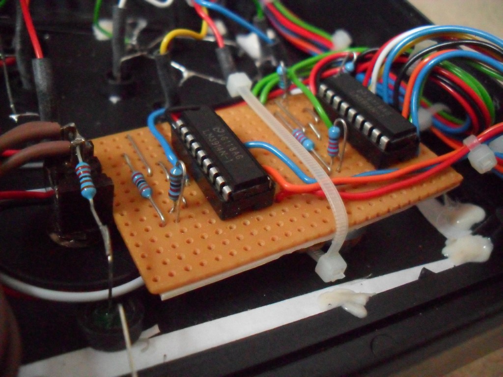
Veroboard showing resistors raised for ease of modification should it be needed as the accuracy of the Pan/Tilt pots has not yet been confirmed.
The Veroboard has been temporarily secured using a cable tie, this arrangement will be replaced with something more permanent when the unit has been proved in service.
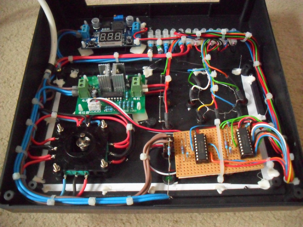
Connector block with two sets of three wires for the Pan/Tilt positional feedback Pots, followed by the Pan and Tilt motor drives and at the end, the brake release feed.
The supply is 24vDC which is reduced and regulated to 12v via board on the right, this is fully adjustable and will be used to tweak the voltages to make allowances for any external cabling voltage drops that are incurred at installation.