Category Archives: Ham Radio

Dummy Load Refurbishment

At a recent surplus sale at my local radio club (Cambridge & District Amateur Radio Club) I bought a dummy load for £5, getting it on the bench the resistance at the PL259 socket measured 88 ohms.

20160216_143116

I also knew that the internal cooling fan was  U/S, so I stripped everything out of the case, ready for cleaning and reassembly.

The tubular resistors have an copper shim inside the aluminium clamping brackets, all parts were cleaned and degreased and put back together, on the rear heat sink I used heat transfer paste, and after replacing the internal fan, installed a cheap thermostatically controlled switch which I got from ebay, the temperature sensor is bonded to the rear resistor clamp .

20160216_142742

The temperature selection is set by dip switches on the PCB, I set the fan to operate when the temperature is greater than 35c, power to the PCB is via a fused 2.5mm DC socket.

20160216_143056

After reassembly the resistance dropped the 46 ohms and the fan kicks in when tested.

My homemade paint tin dummy load works great but the mineral oil is ‘wicking’ up the cables and finding its way to freedom, this one will mean the paint tin being relegated to the shed.

CCTV Pan & Tilt Head Interfaced to Orbitron and Ham Radio Deluxe

I have blogged  previously  about using a CCTV head as a platform for ham radio antennas and have made a manual controller to do this.

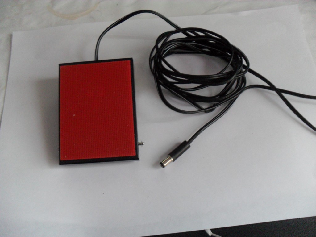
I already have an Easy Rotor Control for my rotator but thought I would experiment with a dual control ERC-M unit in linking it to a Pan & Tilt head I was given.

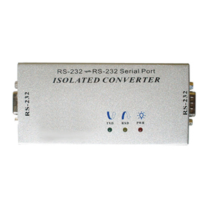
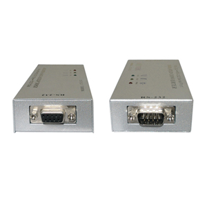
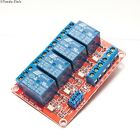
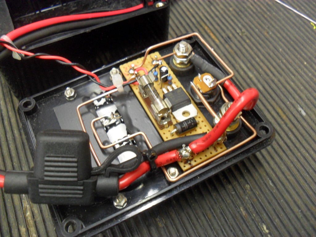
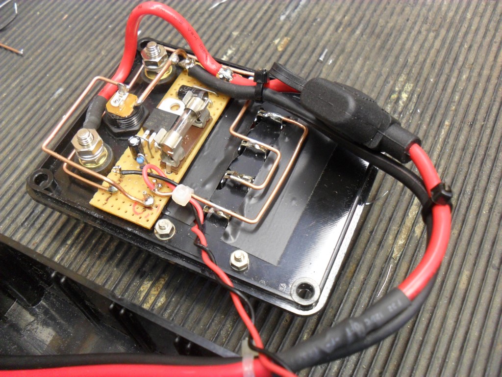
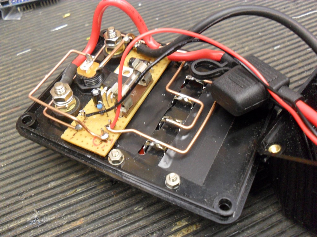
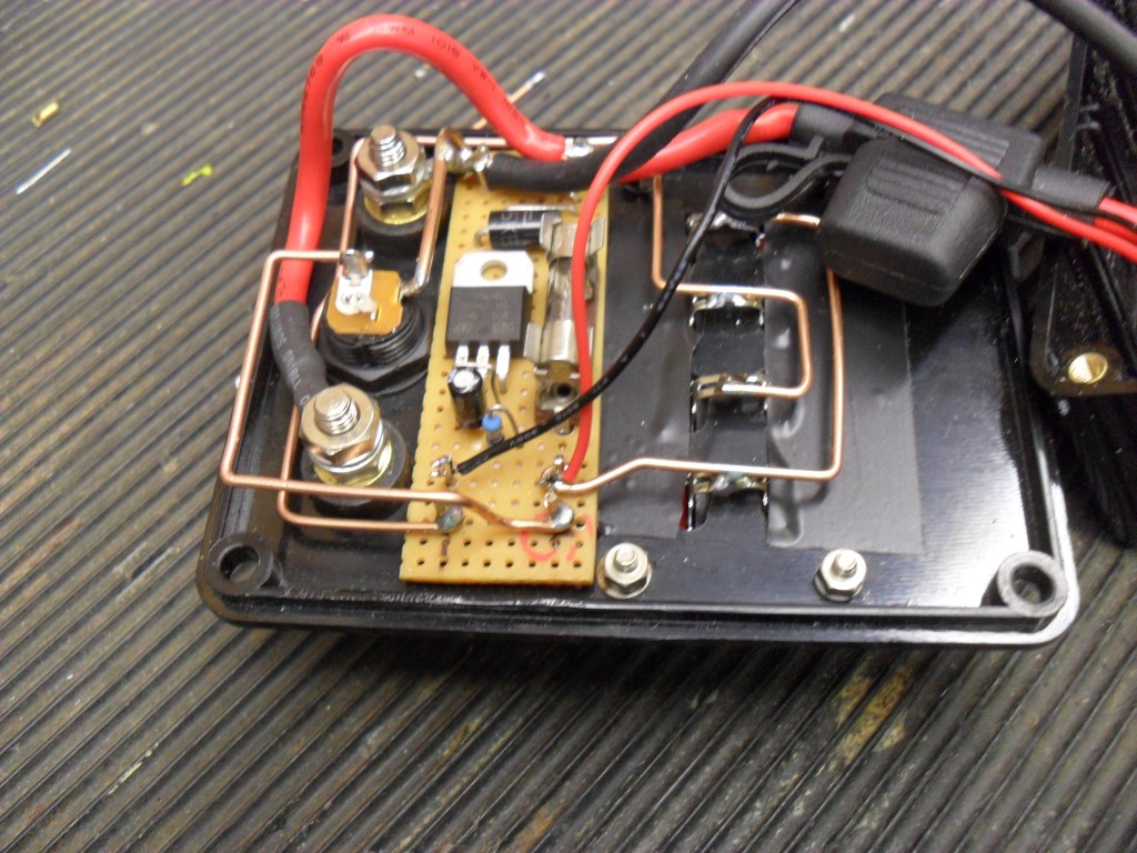
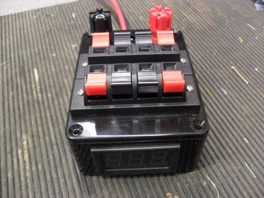
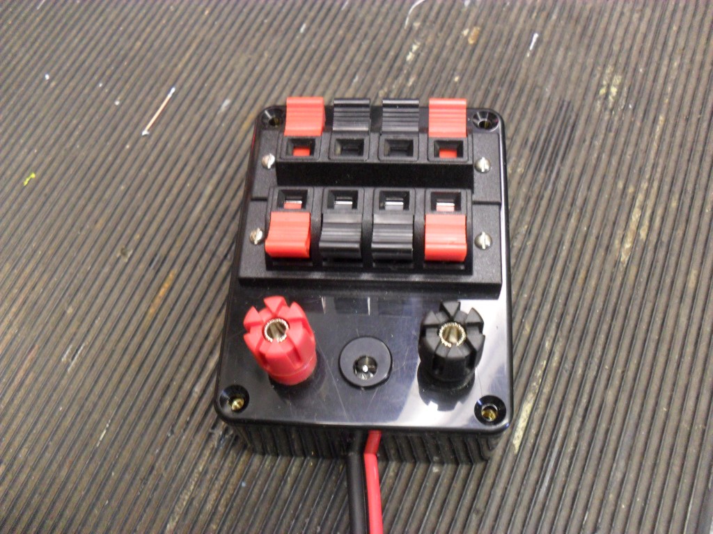
I bought the ERC-M, two Rotorcards and enclosure with matrix positioning display and front controls for this project. The parts came as a kit and took a few hours to put together, a with a previous kit from ERC, the instructions were excellent and the unit operated first time on power up.

The Pan & Tilt head I have is 24vDC, but will work on 12vDC, once the connections were made to the Rotorcard relays, the next step was to calibrate to positional potentiometers which are part of the head and allow presets to be selected. (Note – the positional pots need a 5v to 15v supply across them, this can be taken from the Rotorcard but as no take off terminals are fitted this board, I fed the pots directly from the power supply)

The kit comes with a CD containing all drivers, manuals and instructions plus a calibration program and operating program, I opted for a USB version of the ERC-M, I needed to point to the USB driver location on the CD during the installation of the ERC-M, after installation, checking in device manager confirmed the controller was using Com Port 6.

Setting the calibration program to the correct com port number allowed me to first calibrate the Pan or Azimuth, once this was done after following the on screen instruction I calibrate the Tilt or Elevation, this needs a bearing to be entered when the platform is at the top position or 90 degrees to ground, once this is done, calibration is as the Azimuth by following the on screen instructions.

The calibration software can be closed and the operational software opened to test functionality of the head, clicking on the compass rose will take the head to that position.

I use Ham Radio Deluxe but the garage PC where I do my building has no radio related software, so I downloaded Orbitron satellite tracking software.

As the Orbitron does not have a physical connection to the ERC-M, the program Pstrotator was also downloaded as the interface as this will connect to Com Port 6 and drive the controller, the internal data exchange between Orbitron and Pstrotator is via DDE, this additional file needs to be downloaded from the Orbitron site.

Pstrotator was only used to test concept and I used the demo version which is time limited.

pst

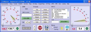
I entered positional settings in Orbitron and clicked on DDE connect (a pop up will say if you need to download this if you haven’t already), if all I well, the positional data details of the satellite you selected will show in a small splash screen.

Opening Pstrotator, enter setting for the Com Port, type of head (Az & EL) and controller (ERC-D), close and then reopen the program, click on ‘track’ and the head will follow the trajectory of the satellite when in range.

A really cool feature of Pstrotator is the ability to take a feed from  a local WeatherUnderground feeding weather station (Chatteris Weather), when high winds are detected, the antenna will automatically turn to the wind reducing mast windage loading.

This use of a CCTV head to position tracking antennas is certainly a lot cheaper than buying a bespoke unit,  CCTV heads are made for external use and have decent torque, jut check if you get one that they are 24vDC and have the pots for presets, these come up all the time on Ebay for about £50, so all in you can have a quality tracking system for about £200.

I will mount the Rotorcards in a small enclosure and move everything next to the rig and interface with Ham Radio Deluxe, I have tested the tracking element with my existing Azimuth rotator, so I don’t envisage any issues with the ERC-M, the next job is to save up for some 8 core cable from the Rotorcards to the head!

Weather Station – Relay Outputs

My weather station software is Weather Display which is unbelievable in what it can do, the author of the software is very receptive to ideas and modifications and has introduced a feature which I and others have asked for, that is the ability for a physical relay to change state when a condition has been met.

Weather Display used to have the feature to operate a 1-wire single relay, but this has been superseded by an 8 Relay module which was not coded to work with the program.

I bought a board and sent it to Brian Hamilton of Weather Display, and within one afternoon had it working  (it did take a few days to get there as Brian lives in New Zealand)!

The feature Weather Display offers is not only control of relays via Weather Display, but using a Phone or Tablet app.

hobbyboard1

The relays can be assigned to Temperature, Wind Speed, Rain, Lightning (depending on sensors) or a timed schedule, these parameters are set and adjusted from a tab within the program.

SAM_5542 (Medium)

The relay board is powered by an external 12v supply with a 1-wire data lead going through a USB interface to the PC, activated relays are indicated by the LED.

SAM_5537 (Medium)

The app allows full control of the relays if configured, or for relays that have been set to ‘monitor’, the state of the relay is reflected on the app.

This addition has brought a new dimension to the weather station, and I will be connecting the ham radio mast motor to the relays, so that on detection of high wind or lightning, the mast will automatically retract (and maybe ground all the antennas so the transceivers wont get damaged).

A further benefit not related to weather is that a relay could be remotely switched to operate the heating or lighting etc, I’m using one to turn on a power supply unit so I can remotely operate power to my transceivers.

Note:   The HobbyBoard relays are not rated for high currents, I will be using these relays to operate higher switching capacity relays.

8 Channel Input/Output Manual shows the versatility of this module.

ON8JL D’Star BabyStar Node

Recently bought a Icom 7100 for the additional features this radio offers, one being DStar enabled, unfortunately I’m unable to access a  remote repeater, hence the BabyStar nodebabystar

This is a small unit with only two physical connections required, these being power (7 Vdc to 15Vdc) and an hardwired internet connection.

When the BabyStar is first powered up it will use an available ip, and this is displayed for a few moments on the screen, typing this ip into your browser opens the BabyStar configuration and status pages.

I have setup in the Icom 7100 a repeater called BabyStar Node, I then lower the RF power of the rig to 0% and simply transmit to the BabyStar and via this, using the internet, to repeaters and reflectors worldwide with FM quality audio both ways.

The version of Firmware on the unit I bought was v1.02, shortly after v1.03 came out, you will need Hyperterminal and a programming lead to complete the update, the process quite easy as the instructions within the User Guide are really good, I found the drivers for the USB to Serial lead here.

Users_guide_dstar_hotspot_v1_01

Hyperterminal is found on older versions of Windows, such as XP, so make sure you have an old PC about!

22 May 2016 – Updated Firmware to 1.04 (I have a copy if you need it)

Updated – 19 September 2021

Removing Mains Hum From Kenwood TS-2000

Since getting headphones, the mains hum on my Kenwood TS-2000 needed to get sorted as it was really distracting.

To confirm the source I powered the rig on a battery and the hum was still their, unplugging the antennas made no difference until I unplugged the RS232 serial lead to the PC, at that point the hum stopped, I then powered the rig from the Power Supply Unit and the hum only reappears when the serial lead is plugged in.

The issue stems from the fact that the PC running Ham Radio Deluxe (HRD) radio program is fed from an Uninterruptable Supply and this has caused a Ground Loop to be created.

I bought off eBay an RS232 opto isolator thinking this would cure it, unfortunately this stopped HRD communicating with the radio so I was stuck! posting the problem on the Yahoo Group forum came up with the answer.

The simple answer from Dave (G4UGM) was not to connect the Serial  pin 5 Ground wire making sure the outer shells of the D9 Socket & Plug were connected, and this did the trick.

(Scroll down for update)

The Serial connections on the Kenwood TS2000 are:

1- Not connected

2- RXD

3- TXD

4- Not connected

5- GND (did not use)

6- Not connected

7- RTS

8- CTS

9- Not connected

The finished unit with pin 5 disconnected goes in the back of the radio, the male and female connectors were soldered back to back, pin for pin except the break of Pin 5  –SAM_5535 (Medium)

29 September 2015     ***UPDATE***

Not sure what changed, but the mains hum came back!!, knowing that a 3 wire opto-isolator didn’t work, I bought an 8 wire opto-isolator from Tronicore, this comes complete with serial leads and a 12vDC PSU (American Power Plug).

I powered the unit from my rig supply, so didn’t use the PSU which came with it, the only other thing I needed was a 9 pin gender changer (Female to Male) to connect to the serial port on my PC.

The interface only works one way round so watch for that, mains hum has gone 🙂

rs232-optical-isolator-3-MEDrs232-optical-isolator-2-MED


Ham Radio Mast Automation – Sensor Type

I have recently bought a winch up mast to gain greater height for my antennas, the electric winch lifts and lowers the inner section.

The 12v winch is designed for All Terrain Vehicles (ATV) and came from Winch-It complete with wireless remote control, in order to use the remote controls out of direct sight of the mast, I fitted proximity switches which detect when the mast is either fully raised or lowered, and then stop the winch.

The short YouTube video shows the type of switch used and its detection distance.

A more detailed mast installation and control blog is HERE.

Note – As demonstrated in the video, the orientation of the magnet is critical for correct operation, also the output from the switch is a signal voltage and a relay module must be used to avoid damaging the switch.

relay interface
Relay Interface Ebay £6.29

Shack Clock Modification

The clock in my shack is one of those which receives a radio signal enabling it to be constantly accurate and it will automatically adjust for British Summer Time, as the contact time in paper and electronic logs is recorded in UTC (Coordinated Universal Time), I decided to get an additional  conventional analogue wall clock and customize it a little.

SAM_5394 (Medium)

The battery powered clock used was described as a kitchen wall clock, item code 257946  costing £3.99 from B&M’s.

I wanted the clock to show 24 hour format, that it was in UTC and my call sign, I decided to print the detail onto 80gsm paper, printing a circular cutting line and stick the addition to the clock face.

I used Visio for the drawing and the template can be downloaded here, a jpg version for editing in paint is here.

The clock came apart by the removal of a few screws, the hands were then removed, the clock mechanism was held in place with a nut, once removed the disassembly was complete.

The printout was cut, and adhered to the clock face with a ‘Prit stick’ type glue and the clock reassembled, job done!

If I had a working colour printer I would have highlighted some of the new detail and maybe even added a picture, but the cost of printer ink is didn’t warrant the expenditure on this little project.

The clock face on the clock I used was slightly over A4 size, if it was less than A4, I would have printed a completely customized new face so no difference in contrast would be seen.

First Australian Receive of M0HTA

I have posted previously about a distant contact logged using the program WSPR using 10 watts, for this Australian contact my transceiver was using the 30m band, mode USB with an output from the rig set to 5 watts.

prog

After the PC clock has been synchronized to the network, I run the software which is linked to my transceiver via serial COM port 1, selecting the chosen band, the software adjusts the transceiver to the correct frequency and will then receive and decode signals, before waiting a pre determined time, before transmitting my station call sign, QRA locator and power output.

Whilst my station is transmitting, other stations who are running WSPR are in listening mode and I’m listening for their signal when I’m not transmitting, this allows a map of interconnections of, I can hear them, they can hear me or both.

oz

I couldn’t believe that within an hour of running the program my signal was received in Australia, up until that point it was mostly Europe which was to be expected, I left the program running for12 hours in total, and the map shows where I had contacted in that time.

Completed Crowbar Circuit Build

Link to Crowbar Circuit Part 1 which has the circuit diagram and part list.

The last part of the project was to mount the circuit in the enclosure, I also bought a panel mounted digital voltmeter which is really useful.

Unit sat on top of the TS-2000 displaying the voltage.

Internal views of the unit, I have modified the board from that shown in Part 1 by the addition of a fuse holder mounted on the veroboard, this has a 2A slow blow fitted and protects the non terminal post outlets.

SAM_5389 (Medium)

SAM_5388 (Medium)

SAM_5386 (Medium)

SAM_5385 (Medium)

SAM_5384 (Medium)

SAM_5383 (Medium)


Kenwood TS-2000 Footswitch PTT via SignaLink Interface

Latest Version – Modified 14 June.

I’m slowly building up my station and thought that a foot operated ‘Push to Talk’ (PTT) would be a good addition, the switch I bought was an Eagle Electronics G028B Momentary foot switch with 6.35mm plug, this is a type used by musicians so is very robust and was bought from Juno Records for £8.41 inclusive of postage, delivery was within 2 days.

SAM_5374 (Medium)

The G028B came with a 6.35mm mono jack plug, this was removed and replaced with a 2.5mm jack as the socket which is used later has a smaller footprint than a large jack socket.

The rig has two connections where it is possible to operate the PTT, the first is the microphone socket on the front of the rig, the other is using a connection available from ACC2 at the rear of the rig.

I was looking at a way of breaking into one of these cables in order to make the connection to the footswitch when I thought of using the SignaLink box as a breakout.

signalink (Medium)

The SignaLink is connected to the ACC2 socket on the rig using a cable marked SLCAB13K, the connection into SignaLink is an 8 wire RJ45 plug.

The connections are (Refer to page 95 of the Kenwood  instruction manual for ACC2 pin functions):

  1. RJ45 SignaLink    3-Kenwood ACC2
  2. RJ45 SignaLink    11 -Kenwood ACC2
  3. RJ45 SignaLink    9-Kenwood ACC2
  4. RJ45 SignaLink    13-Kenwood ACC2
  5. Not connected
  6. RJ45 SignaLink    4-Kenwood ACC2
  7. RJ45 SignaLink    8-Kenwood ACC2
  8. RJ45 SignaLink    12-Kenwood ACC2

The existing SignaLink configuration links for my rig was:

  1. SPK
  2. MIC
  3. PTT
  4. —  Use this to connect to Footswitch and 8.G to operate PTT
  5. G
  6. G
  7. G

The unconnected pin 4 from the RJ45 is connected to pin 13 on the rig, this allows the PTT to operate and NOT disconnect the Mic.

SAM_5367 (Medium)SAM_5368 (Medium)

I left enough lead on the footswitch socket so it will thread through the SignaLink enclose without taking the socket apart.

Removing  jumper 8 out of the holder, strip a small section of insulation and solder the flying leads to the outer of the 2.5mm footswitch socket, returning the jumper to the same position as it was removed from, for the  inner connection of the 2.5mm socket a wire was inserted into he empty number 4 socket on the side nearest the RJ45 socket.

SAM_5379 (Medium)

SAM_5372 (Medium)

This turned out to be a quick, cheap and neat workaround rather than hack into cables or adding additional plugs and sockets to make a breakout.

All done and working in under an hour,  the footswitch is ‘press to make’ it does not need to be left plugged in, so can be put out of the way until needed.

Hope this was useful.