
NOTE – Thanks to Stewart (G0LGS), no consideration was given to the current carrying capacity of the veroboard tracks, which turns out to be just under 6A, so, if you are going to make this, please bear that in mind.
I was looking for a simple circuit to protect my radio and auxiliary equipment from overvoltage and found a circuit diagram and full description amongst other useful projects on Phil Salas – AD5X site – www.ad5x.com/articles.htm.
The voltage protector file including circuit diagram and full parts list is available for downloadable here – Vprotect.
The circuit is designed to ‘blow’ the supply fuse to the equipment in order to protect it, the protection is from reverse polarity as well as transient spikes and damaging overvoltage.
The specification for the Kenwood TS-2000 is 13.8v +/- 15% ( Total Maximum voltage 15.87v), this circuit will only allow 14.8v to pass before the protection crowbar circuit operates.
The components are sizes for 40A, the Kenwood maximum current draw is 20.5A, so well within capacity.
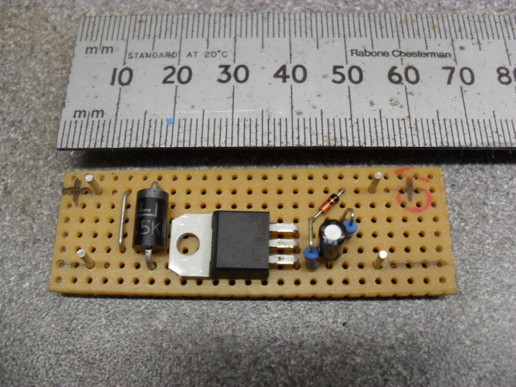
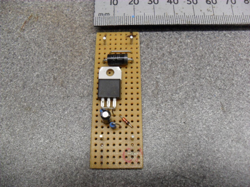
The circuit board could have been made marginally smaller, but I was too lazy to trim it down!
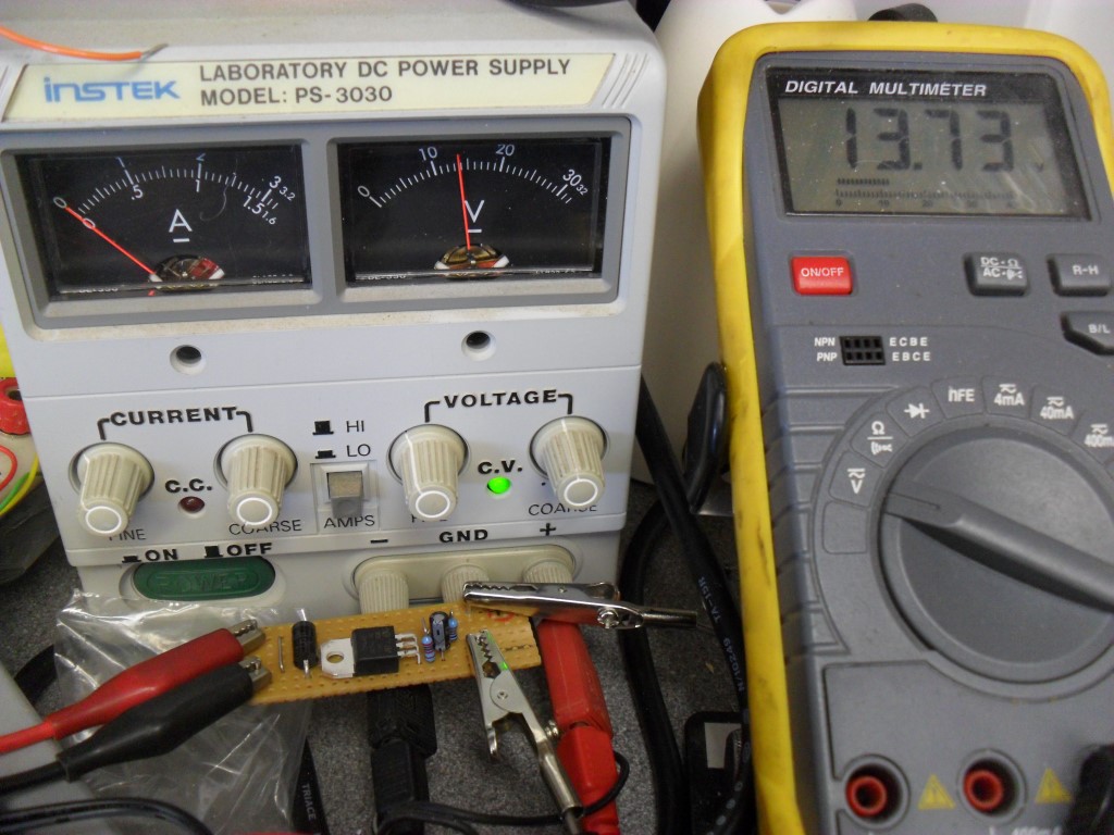
This shows the test setup with the power supply units (PSU) current trip set low in order to monitor the tripping voltage, on the left of the PSU in between the knobs marked CURRENT, their is a small LED with C.C. for Constant Current, the circuit is working passing 13.73v to the meter.
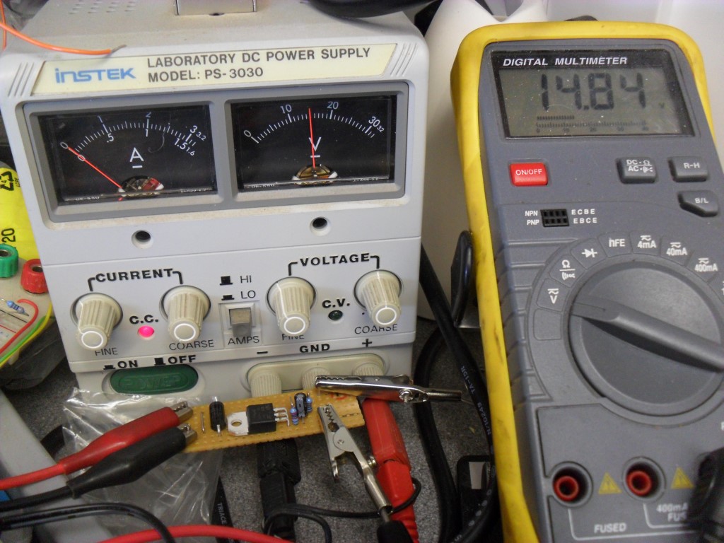
The voltage from the PSU has now been increase past the crowbar limit of 14.8v and the C.C LED is ON showing that if this was a fuse it would have operated to protect the transceiver, 14.8v is the maximum voltage that will ever reach the transceiver, no matter what!
Parts: – These were from UK ebay
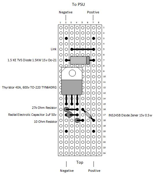
1.5KE 15 TVS Diode 1.5KW 15v DO-21 – £1.69
Thyristor 40A, 600v TO-220 TYN640RG – £3.19
IN5245B Diode Zener 15v 0.5w – £1.42
Radial Electrolytic Capacitor 1uF 50v – £0.99
Resistors 27k, 10 Ohm and Veroboard I had already
Less than £8 to protect an expensive radio, filtered speaker etc. pictures of completed unit is HERE.
Hi There, Do you have a circuit diagram for this over voltage crowbar. I have just acquired a old power regulated 30A supply. I have check and it has short circuit protection, however nothing for over voltage.
Could you please get back to me.
73
Mike – ZL1MRC
Hi Mike,
Thanks for getting in touch, the original diagram link was broken which I didn’t know, I’ve added a link to the original author and as a backup, downloaded the article, so hopefully losing a link won’t lose the information.
All the best with your construction.
Hi!
I was studying the original article, and noticed the author mention the capacitor value as 1uF in his text, but 10 uF on his schematic and on his parts list. I see 1uF has been used here. So it’s currently (no pun intended :D) a two all draw. Can we settle it on penalties? Which one is right? Or is it not too critical?
I will be building this, as I once had a 13.8v linear PSU start putting 16.5v into a radio, and I only spotted it by how bright the light was on the signal meter.
Hi Chris,
The original article (now a dead link unfortunatly) said that a 50v 1uF was acceptable which is what I have used and it tested fine.
This is fascinating, thanks.
As a novice I am trying to protect a circuit that is 13.8VDC with a max rating of 10A.
I am having issues translating the components that you have used for your build to my own requirements.
I am using RS Online for components: http://uk.rs-online.com/web/
Any help would be appreciated
Hi Kirk,
The components listed in the blog will be fine, the way the crowbar circuit works is dependent on the voltage rising above a set trigger and then basically presenting a short circuit across the power supply and in so doing, blow the PSU’s output fuse.
The fuse is sacrifical to saving the rig from damage, the components used in the blog circuit will work just as well if the load taken from the PSU is 10A.
Hope this helps.
I’m a little puzzled by the circuit arrangement.
Why are both a TVS and a Thyristor used ? When one or the other would probably suffice.
I suspect that the Zener / Thyristor / etc in your test is not doing anything – if it was doing its job when the voltage from the bench PSU reached the 15V or so threshold set by the Zener the voltage across meter (with a current limited supply like shown) would only be the forward biased voltage of the conducting Thyristor (about 0.7V).
Hi Stewart,
I’m no electronics engineer, the description from the circuit author is:
In this circuit,the 1.5KE15A still clamps and absorbs fast over-voltage transients as well as provides
reverse-voltage protection. However, longer sustained over-voltage conditions, such as a
power supply that loses regulation, will trip the triac which will blow the fuse. The 1uf
capacitor makes the circuit insensitive to very short duration transients and noise on the
incoming DC line. With this circuit the 1.5KE15A diode won’t fail with any overvoltage
condition.
Not sure if this helps or not.
So ignoring that the Thyristor is not conducting (as the voltage across it would 0.7V) in your second picture (see my previous comment):
The thing that really concerns me is that original PDF suggests that 25A fuses are used – the track on the the Vero board will not carry in excess of 25A for very long (i.e much less time than the fuse will).
The circuit in this form is probably good only for a Power supply rated and fused for 5A or less, for anything else the connections to the Thyristor Anode and Cathode need to be much more substantial.
Stewart,
That is a really good point and to be honest not one I had given much consideration, Google found me this:
The track of a stripboard is 2mm (78 mil) wide. The holes drilled into them are 0.8mm (31 mil) in diameter, leaving a total (0.6mm [23 mil] on each side of the hole) of 1.2mm (47 mil) for a maximum usable current path. Thickness of Veroboard/Stripboard at 1 ounce per square foot is 35 microns (1.37 mil) thick.
Assuming that you have an ambient of 25 degrees C (77F) and can tolerate of up to 50 degrees C (90F) more, then fed into a pcb track width calculator it spits out:
5.4 Ampere
Strip Board Trace Width Data
I will amend the blog to this issue.
Many thanks for taking the time to give the circuit and its construction, due scrutiny.
In the article by AD5X, he first described a mega simple version using just the 1.5KE15A TVS diode on Its own with fuses. Why complicate the circuit further? This first simple version seems more than adequate or am I missing something?
Hi Nigel,
This has been pointed out previously, I opted to build the circuit with the additonal elements, but your not missing anything.
Ian
Hi Ian,
Thanks for responding. I am going to knock up a couple of the simple ones – Diode and a fuse and simply solder em into the power leads and shrink tubing over. Gives a bit of peace of mind eh?
73
Nigel G4BSW
Good move.
The circuit offers protection against over-voltage, but what happens if you accidentally reverse the polarity of the power cables?
Hi and thanks for checking out the blog.
The circuit is designed to protect the radio, therefore, if you accidentally reverse the polarity it will put a direct short across your PSU and operate the PSU’s fuse. An easy fix to guard against this would be to put another diode in series with the supply positive.
All the best
Thanks for answer, i really loved this circuit and i will try build it, thanks!