Ameritron RCS-8V interface with Ham Radio Deluxe

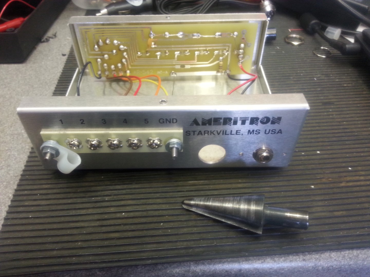
I bought a Ameritron RCS-8V 5 way antenna switcher from Ham Radio Outlet, this uses a rotary switch in the shack to select a remote relay to energize, this allows up to 5 antennas to use a single coax.

20160514_160618

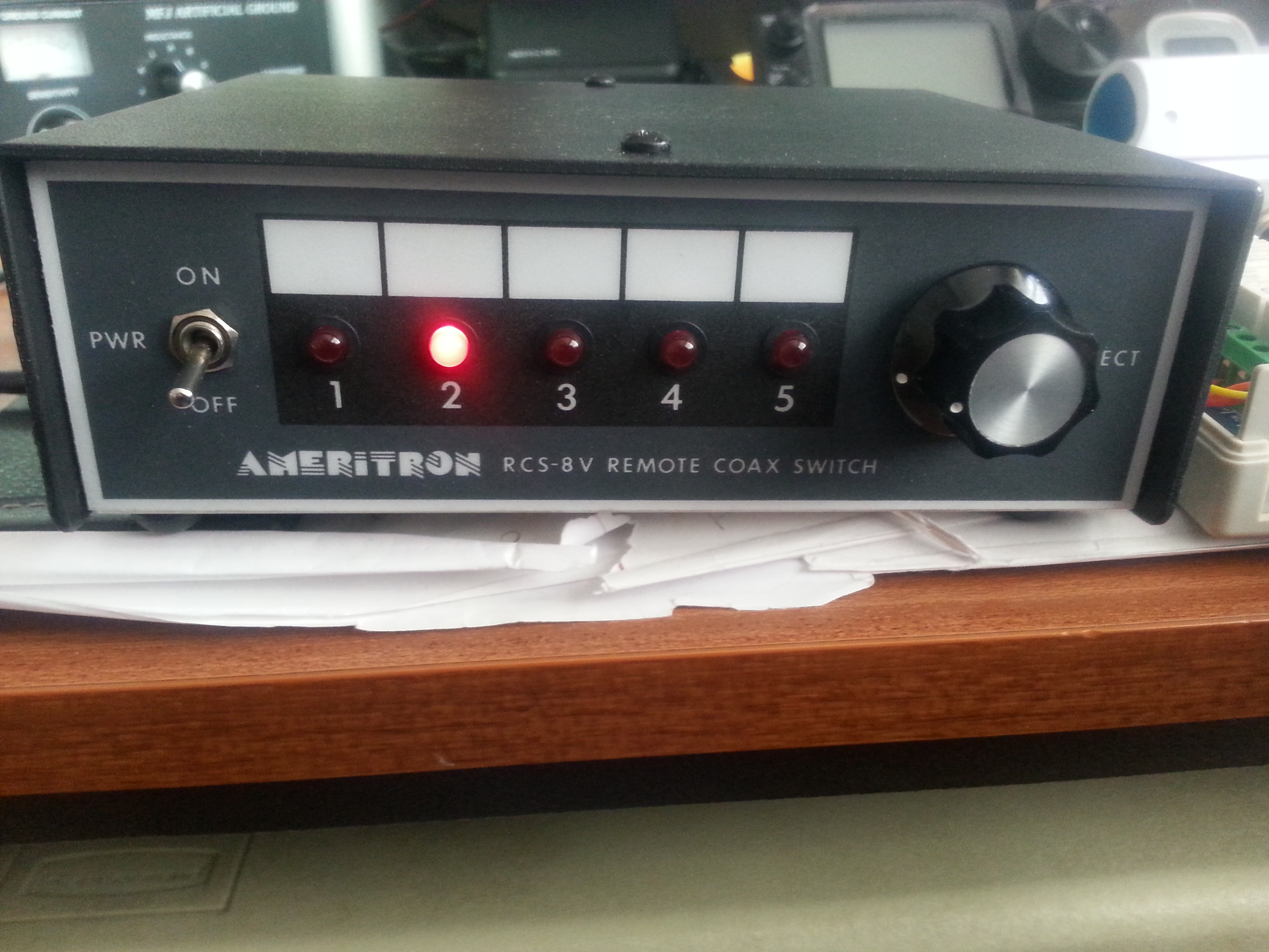
I use Ham Radio Deluxe as my program of choice, this software has a feature to allow automated switched depending on the Band in use via the computers Parallel Port (Auxiliary Switching).

8 relay

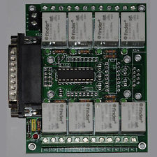
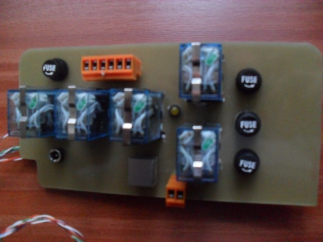
I bought an 8 relay interface off eBay for £18 and mounted it inside an enclosure, the Parallel lead from the PC to the interface was also from eBay and cost £2.

20160416_174101 (Large)

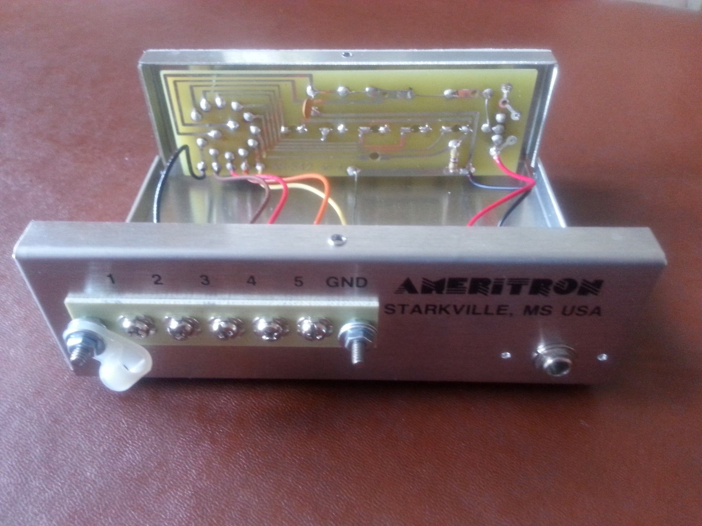
The inside of the RCS-8V is a simple two pole rotary switch, one pole switches 12v to the panel LED, the other pole switches 12v to the output connections for the relay.

20160420_182513 (Large)

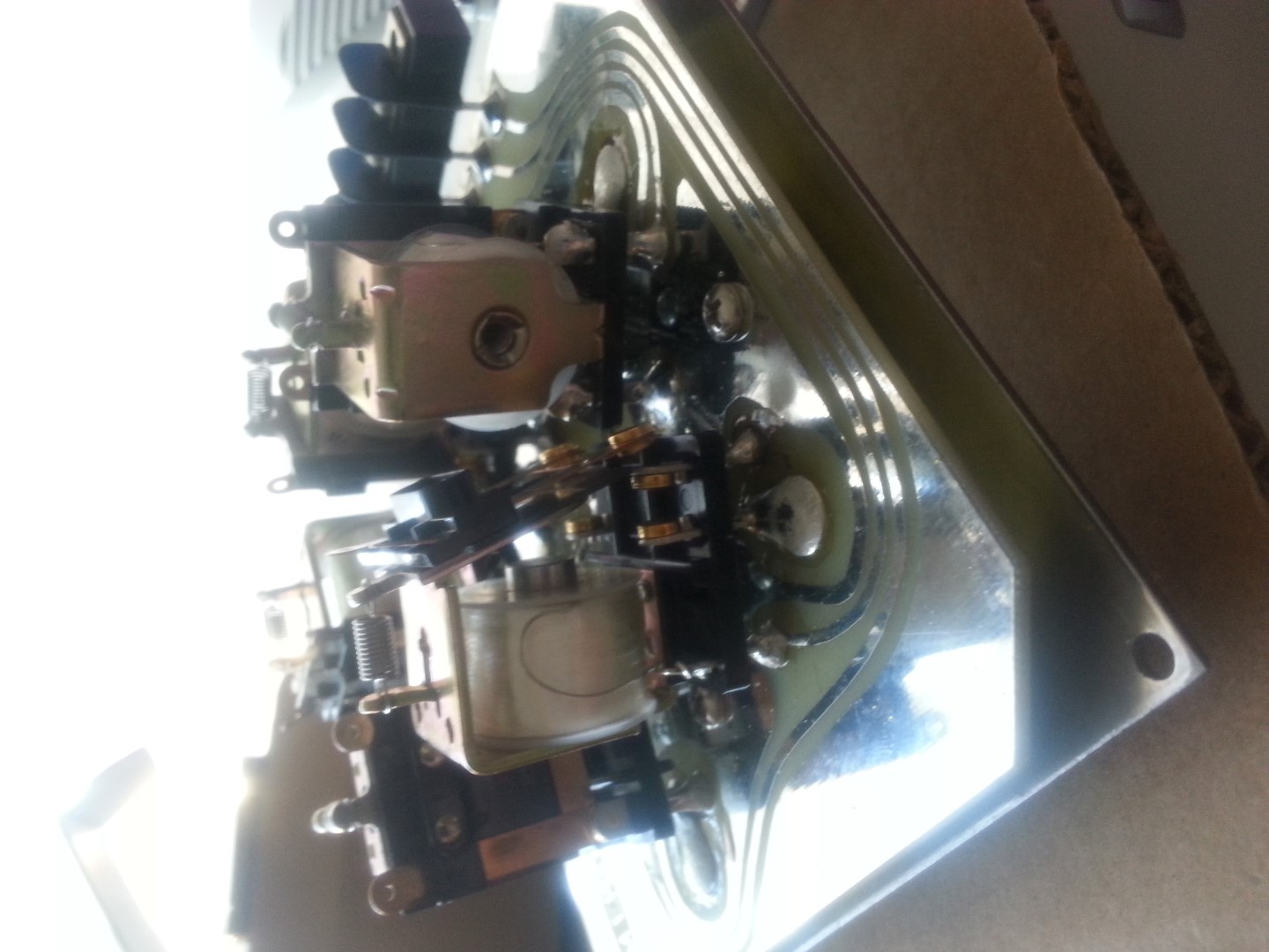
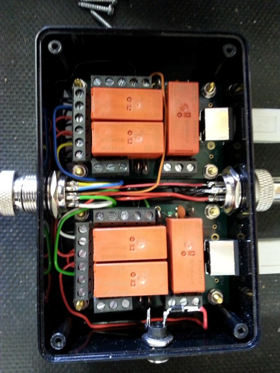
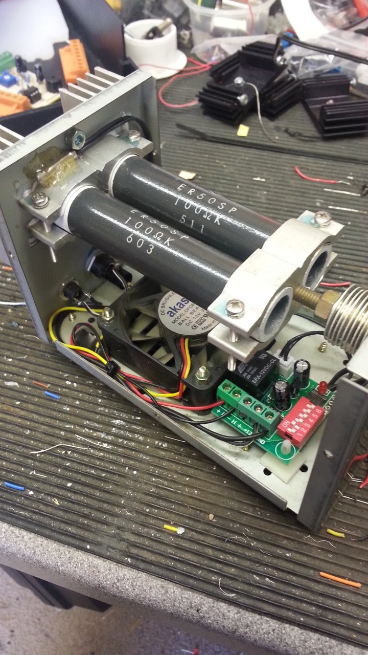
The above picture is of the opened external relay unit, the first thing I noticed was that the relay armature had jumped out of position in transit and was on the wrong side of the contact, this fortunately was easily sorted.

20160417_142116 (Large)

The On/Off switch on the RCS-8V is a single pole double throw, I decided that for normal operation,  when the RCS-8V  was in the ON position, control was only via the rotary switch, with the switch in the OFF position, control of the RCS-8V  will be from the relay interface, power for the interface will also be switched from the RCS-8V.

The connection from the interface to the RCS-8V  is via an 8 pin connector which needs a16mm hole.

20160423_103244 (Large)

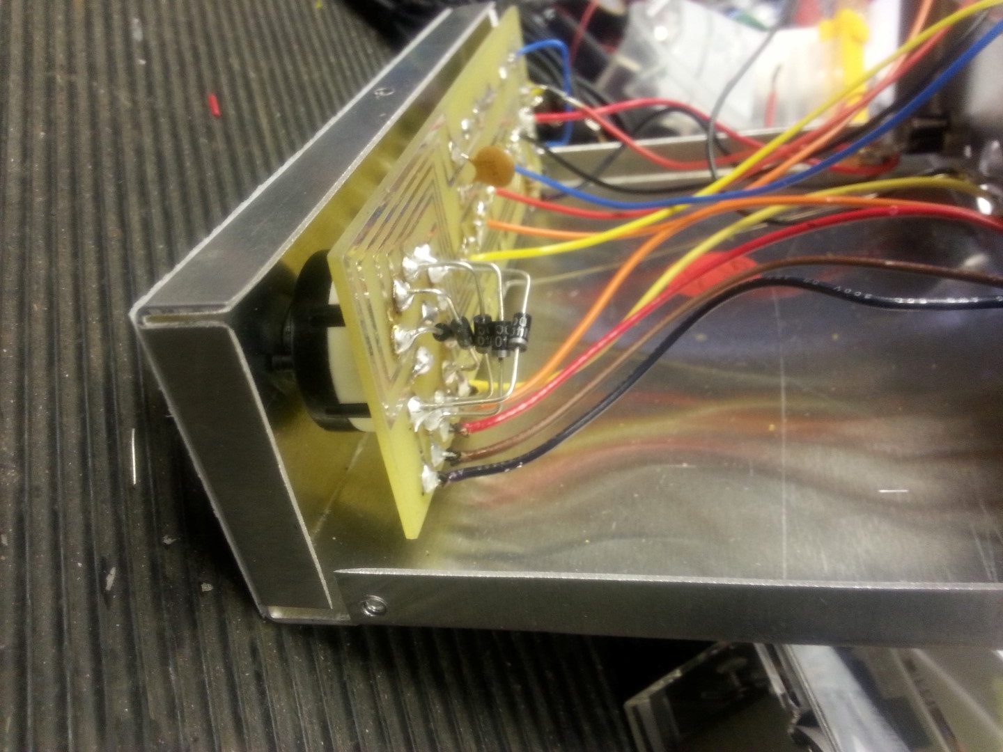
Diodes were soldered across the rear of the rotary switch, this allows independence of switching, so if the rotary switch is left on antenna relay 3 for example, when the front RCS-8V switch is set to OFF, power is applied to the interface and whatever relay switches becomes the master (example below).

20160515_111510

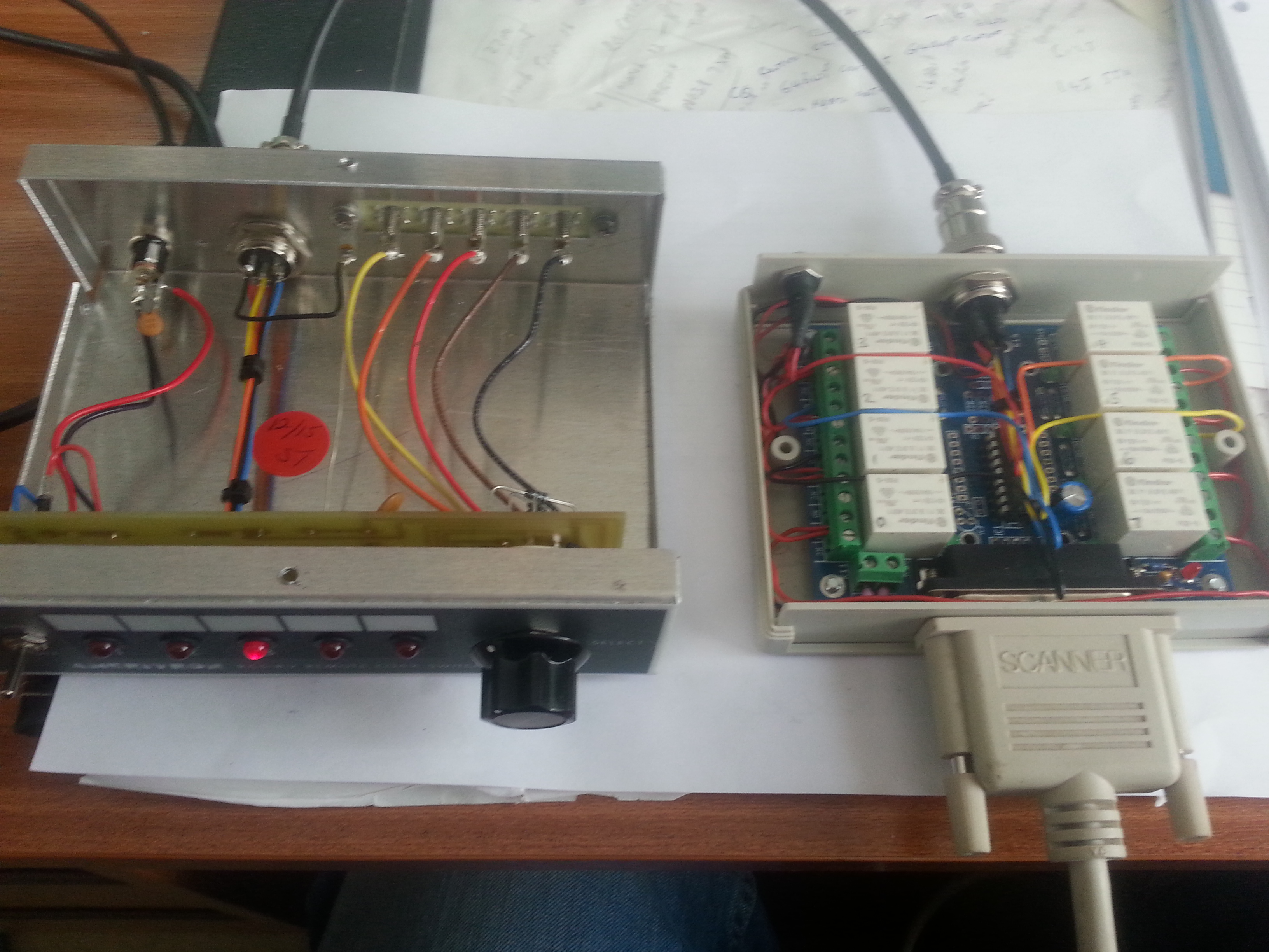
RCS-8V switched ON, no power to relay interface, rotary switch selected antenna 3.

20160515_111519

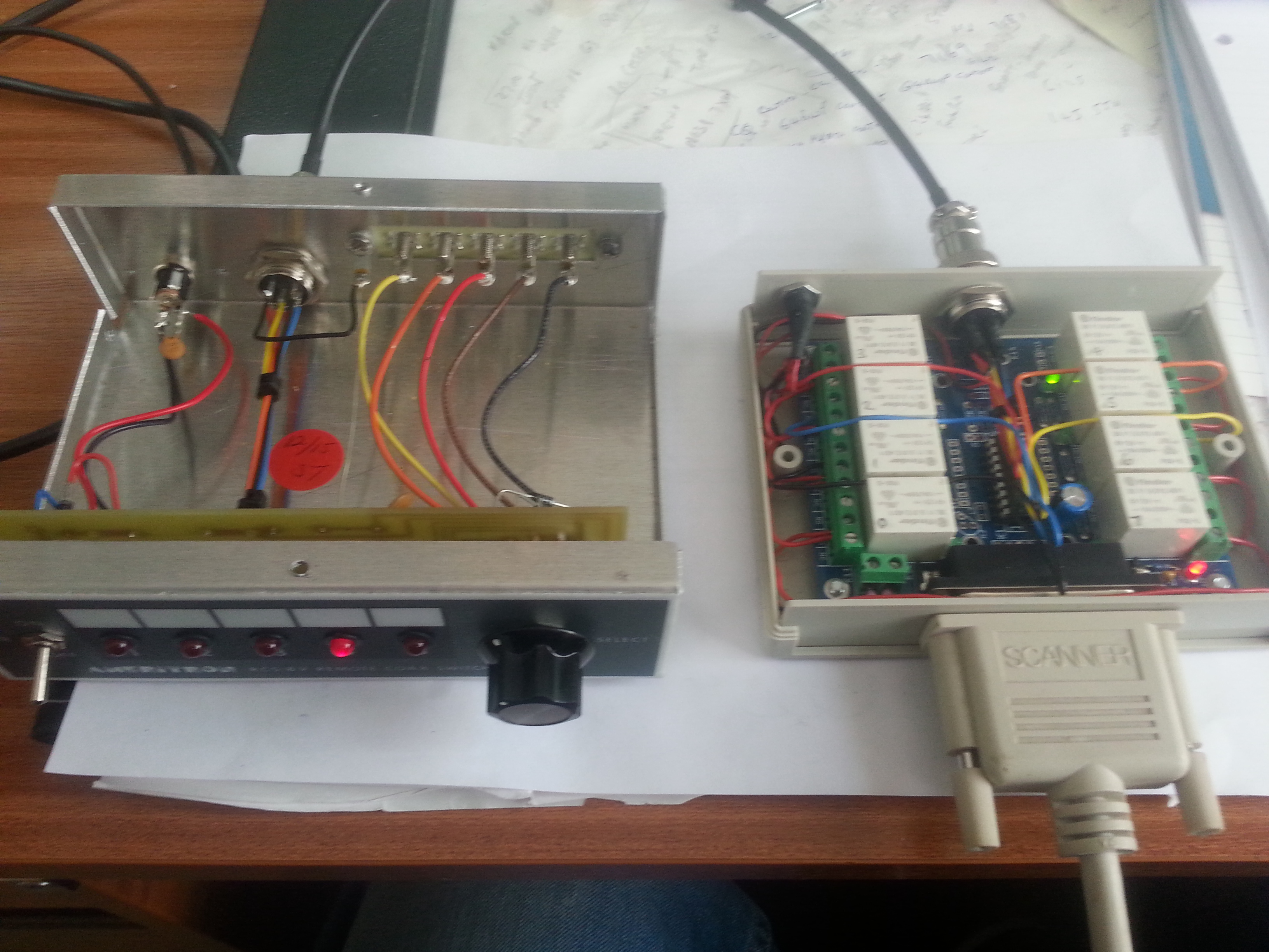
RCS-8V switched OFF, power to relay interface ON, relay 4 switches antenna 4.

Cambeam 2016 the Cambridge & District amateur Radio Club newsletter has a great article on using an Arduino for automating antenna relay controls and is worth checking out. Article by Bob Cowdery G3UKB.

Mag Loop

Had a play with my Mag Loop project, the problem I had was that the stepper motor which turned the Vacuum Capacitor introduced a lot of noise into reception, removing the supply from the stepper motor caused the bellows in the capacitor to return to a resting position, knocking the tuning out.

To combat this I have fitted a friction brake which uses a terry clip to the shaft of the motor, this seems to work ok, but a bit more work needs to be done.

20160502_131715 (Small)

The loop tuned perfectly on 3Mhz, pity it’s out of band, oh well, a job for another day!

20160502_140402 (Small) 20160502_140415 (Small)

Widow Maker Plug Top

I was given a 13.8v Power Supply Unit at a local radio rally so thought I’d check it out, first job was the plug top, this is what I found;

20160502_111900 (Small)

I rewired the plug and used the optional extra strain relief, this was the before picture.

20160502_112541 (Small) 20160502_112548 (Small)

It was only after I put the plug back  and inspected it, that I noticed the condition of the outside of the plug and the lethal exposed conductor.

Once a new plug was fitted the PSU worked fine, just a cautionary tale, always double check everything from a rally.

Another Blitztortung on the Network

I helped out another Blitzortung lighting user by building up his kit, this one is now up an running in St Thomas, Virgin Islands, the pictures below show the various stages of PCB build, the firmware program and that the GPS has picked up satellites to time lock the strikes.

St Thomas Blitzortung Stats.

blitz

Red Arrows show location of St Thomas detecting lightning 2,300 miles away!

2016-04-07 17.08.28 (Medium)
2016-04-07 16.16.23 (Medium)
2016-04-09 09.36.11 (Medium)
2016-04-09 11.25.16 (Medium)
2016-04-09 11.12.26 (Medium)
2016-04-09 11.25.25 (Medium)

Radio Mast Automation Proximity Sensors

Updated 8 June 2023

This Blog post went into detail on the sensors used for the mast position, I have found reasonably priced ferrous metal inductive proximity switched, these are non contact devices with a detection range of 5mm which is perfect for my application of securing pin detection, feeding into the masts PLC logic controller.

2016-04-09 17.11.08 (Medium)

Sensor mounted below bottom mast securing pin hole, the sensor was fixed the mast by drilling and tapping a 6BA hole, the HSS drill size of 2.3mm for a 6BA tap cost 99p for 10 from Hong Kong, the machine screws which come with the sensor appear to be  imperial and were discarded.

2016-04-09 17.11.16 (Medium)

Test position for alignment and operation checking.

2016-04-10 11.10.42 (Medium)

Lower pin sensor finished with a three pin male Superseal waterproof connection, the female will break out of the 10mm convoluted conduit via a hinged tee piece.

2016-04-10 09.48.15 (Medium)

Top mast securing pin sensor being fitted, this pin stops the mast from tilting down (Luffing), the output from this sensor, like the bottom pin detector will influence the functions available in the PLC controller, for example, if the mast is elevated and the top pin is removed, the mast will not lower as this is an unsafe condition.

sensor

The next stage is the mounting of the controller cabinet and wiring which can be found HERE.

Update 20 July 17 – Top proximity failed and had to be replaced, no sign of water ingress and the potting and cable entry look in good order, so not sure what the cause of the failure.

Extrernal Link to Inductive Proximity Sensor Technology blog.

Orbitron & PST Rotator Interface with Easy Rotor Control

This blog is an update of this – Pan & Tilt Orbitron Interface post as I’ve added some pictures of the kit used and I have finally got round to putting the Rotorcards in a decent enclosure.

The main controller is a ERC-M USB kit which interfaces with the PC and programs which are running , the Rotorcard relays  are controlled by the ERC-M, the Rotorcard also provides a positional feedback to the ERC-M.

Front panel of the Desktop housing for the ERC-M, the front panel has manual buttons for up/down tilt & left/right pan, LED's also show when internal relays are operated.

Front panel of the Desktop housing for the ERC-M, the front panel has manual buttons for up/down tilt & left/right pan, LED’s also show when a signal is sent to the Rotorcard relays.

The two yellow LEDs on the left hand side indicate the signal to the auxiliary relay.

The LCD display is showing the position in degrees, the number after Az or El is the feedback from the Pan & Tilt head, the numbers on the other side of the > are the output from the software, the ERC-M compares the two values and energises the appropriate relays which in turn operate the motors in order to keep the values aligned.2016-04-01 12.04.05 (Medium)

The ERC-M kit is the top left PCB, the desktop housing is also a kit comprising of the LCD display and front panel buttons.

2016-04-01 12.04.33 (Medium)

The PCB mounted inside the desktop housing is the 13.8v to 10v voltage regulator which provides a stabilized supply to the Pan & Tilt heads positional potentiometers.

An external 13.8v supply is required in order to drive the high current motors of the Pan & Tilt head.

2016-04-01 11.37.03 (Medium)

The two Rotorcards (one for Pan the other Tilt, or more correctly Azimuth and Elevation respectively) are enclosed, 13.8v can be fed to the relays here or at the desktop housing.

2016-04-01 12.01.25 (Medium)The three outputs from the ERC-M enter on the right hand side to the Rotorcards, the middle connector is the 13.8v – 0v – 10v supply.

The top Rotorcard relays operate for clockwise or anticlockwise supply to the Azimuth motor, the third relay is not used (auxiliary relay) as the Pan & Tilt head does not have an electro-mechanical brake fitted, if it did, relay three would operate in advance of the motor supply relays.

The bottom Rotorcard is for elevation, Up & Down.

On my version, the ERC-M is connected to a PC via a USB connection to Com Port 6, the position of the heads has already been calibrated using the provided software from Easy Rotor Control.

To start tracking satellites, the first step is to open Orbitron.

2016-04-01 11.56.40 (Medium)

This is a free download program, each time it is ran, check that the TLE files have been updated then select the satellite of interest from the right hand list, once this is done, click on the satellites on screen icon.

On the bottom tabs, select rotator and click DDE a small box should now open on the screen with live positional data of the selected satellite showing,  (a separate download is needed for the DDE function).

Open PST Rotator program:

2016-04-01 11.56.55 (Medium)

Using the PST Rotator settings configure the program to respond to Comm Port 6, use Orbitron as the controlling program, that the type of head ouput is GS-232 and Az/El is selected.

When the program is set to ‘Track’ as the above image, the displays show the actual position of the Pan & Tilt head by a black line with the green line showing where the head needs to move to, the green line is controlled via DDE from Orbitron.

A further setting I have enable is the link to weather information, this allows the mast to rotate into the wind when a trigger speed has been reached, this reduces wind loading on the mast and antenna.

2016-04-01 11.36.20 (Medium)This is a Dennard CCTV Pan & Tilt head and operates at 24v, 13.8v works it just fine with a maximum current draw of 600mA, I have commoned the potetiometers supply, so the minimum number or wire cores is 8:

2 – Pan Motor

2 – Tilt Motor

2 – 10v supply across positional potentiometers

1 – Signal feedback from Pan

1 – Signal feedback from Tilt

The next stage is to get some decent antennas for satellite reception.

4m band dipole finally fitted

My local area has quite an active 4m band, and recently Andy (G6OHM) has gained an NoV for a 4m simplex parrot which is working well.

Kevin (2E0OPU) kindly gave me a 4m band dipole as he knew I had an Icom 7100 and no antenna, so I finally got round to installing it.

I did a temporary setup at ground level and got the VSWR to 1.0:1, mounting the antenna in it’s fixed location would not allow me to get the VSWR below 1.6:1 (this would give me a reflected power of 5.3%).

The cause of this problem was the close proximity of my mast, extending the dipole 300mm past this structure solved the problem.

2016-03-29 09.23.49 (Medium)

The dipole is horizontal for an SSB contest at the moment, I have used a stand off sleeve which the dipoles supporting tube slides into, this allows me to retract the dipole for fine tuning, a self tapping screw is used to hold the dipole either horizontally or vertically.

The bracket for the dipole was their before the mast, hence in the horizontal plane, the dipole it is across the mast stopping it from tilting for maintenance, as I have to get up the ladder to pull the mast top securing pin, it’s no big deal as I will move the dipole out of the way at the same time.

The VSWR is 1.0:1 or as near as damn it!

2016-03-29 09.11.03 (Medium)

Radio Mast Automation – Part 1 – PLC or Relay Control

Note – This is the starting point in my mast automation project, several things ‘evolved’ during the overall project, therfore as you read through this and get to the end of the Parts, you can see the changes, tweaks and additions which have improved the project.

===================================================

My mast has an winch to raise and lower the inner section of the mast.

This project is to fully automate the process and add a level of intelligence into the mix, my requirements list is:-

  • Automatically stop the motor at the top or bottom
  • Run-On when mast lowered to release tension from cable
  • If bottom mast inner securing pin is in – Stop mast from raising or lowering
  • Disallow inputs whilst the motor is either lifting or lowering
  • Safety timer on the motor operation should a limit switch fail
  • Means to stop holding an input button increasing the motor run time
  • Don’t lower the mast if the luffing pin is removed
  • Override to allow either a pulsed automatic operation or manual hold for up & down ignoring limit switches
  • Emergency stop
  • All timing sequences reset on restoring emergency stop or override to prevent motor operation
  • Interface with WX Station to automatically lower
  • Visual display of status – what is doing what
  • Automatic battery charging after a number of counted operations or weekly – whichever comes first
  • Battery charging does not interfere with solar panel charging

I was going to use relays, and made a start on the construction, but the more I thought about interlocking and timers the more unrealistic this option became.

SAM_5618 (Small)

The relay unit currently in use which works fine is shown below, two of the relays are for the raise and lower switches, the other two are for overrides.

SAM_5472 (Small)

My plan is to use a Programmable Logic Controller (PLC) which needed to have 12 inputs and 4 relay outputs.

I found a company on the internet called Audon.co.uk, the model chosen was ELC-18DCD-R-U at £69 ex VAT and I also bought a RS232 programming lead for just under £20 ex VAT, the PLC has a voltage range from 12 to 24v DC is very compact and will do everything I need and more.

A major plus was the programming software is free and very easy to use.

elc_18_c

Link to PLC Software Link

Link to PLC Manual

The drawing shows the sensor positions, currently the mast only has up and down limit switches fitted, the upper and lower securing pin detection will be fitted when the parts arrive from the other side of the world.

Mast Contro2l

The way of working will be:

Normal Up & Down

Momentary pressing of the down button on the remote hand held winch unit, will fully lower the mast, pressing the up button will do the reverse.

Luffing the Mast

Luffing (Tilting down) of the mast for maintenance will involve setting the PLC input switch to Luff, this will only lower the mast if the mast is lowered, the lower securing pin is in and the upper securing pin is out.

The logic plan shown below has been imported from the software program into Visio and I’ve added some idents to make it easier for me to fault find at a later date.

Descriptors for the idents is below.

The next stage of the project is to mount the PLC in an enclosure and fit the securing pin sensors, please see Part 2 HERE.

Dummy Load Refurbishment

At a recent surplus sale at my local radio club (Cambridge & District Amateur Radio Club) I bought a dummy load for £5, getting it on the bench the resistance at the PL259 socket measured 88 ohms.

20160216_143116

I also knew that the internal cooling fan was  U/S, so I stripped everything out of the case, ready for cleaning and reassembly.

The tubular resistors have an copper shim inside the aluminium clamping brackets, all parts were cleaned and degreased and put back together, on the rear heat sink I used heat transfer paste, and after replacing the internal fan, installed a cheap thermostatically controlled switch which I got from ebay, the temperature sensor is bonded to the rear resistor clamp .

20160216_142742

The temperature selection is set by dip switches on the PCB, I set the fan to operate when the temperature is greater than 35c, power to the PCB is via a fused 2.5mm DC socket.

20160216_143056

After reassembly the resistance dropped the 46 ohms and the fan kicks in when tested.

My homemade paint tin dummy load works great but the mineral oil is ‘wicking’ up the cables and finding its way to freedom, this one will mean the paint tin being relegated to the shed.

A blog about stuff that interests me or I have done.

Social media & sharing icons powered by UltimatelySocial