Thought I’d give an update on the mag loop project, I’ve been busy making the capacitor support, as it is important to reduce resistive losses, I mounted the capacitor using 1.7mm thick sheet copper, the main mounting is one side of the capacitor and I have brought the connection off using 28mm copper pipe, this goes to a compression fitting in which I have also soldered the olive the reduce where possible electrical resistance.
The reason for using 28mm pipe is that I can use pipe reducers when I come to play with different pipe thicknesses and configurations.
The top of the capacitor is the second terminal, I bought a small piece of 54mm copper pipe, after putting a small slot in the side, this slides neatly over the end of the capacitor and is secured in place with a jubilee clip, a 28mm copper stub pipe was soldered onto the 54mm piece completing the loop terminations.
The capacitor assembly is mounted on a cut down plastic bread board, the shaft from the capacitor has a flexible 12mm to 6mm coupling reducer, the linkage to the stepper motor is with 6mm diameter nylon threaded rod, this allows for conversion of rotary movement to linear movement is I decide on using limit switches or positional potentiometers at a later date.
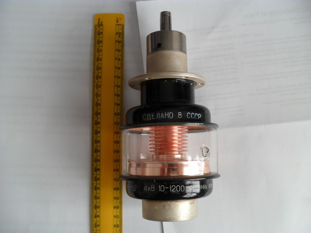
The stepper motor is a Bipolar NEMA 17 200 step, 12v @ 350Ma, the 5mm motor shaft has a flexible coupling affixed, this not only compensates for any out-off alignment but also allows the 6mm threaded rod to connect to the 5mm shaft. Nylon was chosen for the motor linkage as this insulates is from the high voltages which develop across the capacitor when in use and the motor, the capacitor is rated ay 4Kv and I will have to throttle back output power to ensure this is not exceeded.
I opted for a stepper motor over a DC motor after reading that the brush noise could be a problem, it is easy to convert from stepper to DC should I need to in the future, it is also easier and cheaper to control a DC motor, so I did consider this option before committing to the stepper motor.
I’m using an Arduino Uno clone (www.sintron-hk.com) with an 5v rotary encoder, the Arduino is connected to a A4988 Stepper Motor Driver Carrier with Voltage Regulators.
The A4988 can be supplied with an input voltage of up to 35v and it has on board 5v and 3.3v regulators, this reduces the need for external components or the need for a separate power supply for the motor and logic circuits, I use the A4988 5v output to power the Arduino when in use making for a neat solution.
![20150315_184832[1]](http://www.chatteris.biz/blog/wp-content/uploads/2015/03/20150315_1848321-300x169.jpg)
This is the unit on the desk allowing me to play and tweak.
Link to YouTube video showing the control of motor.
Although not shown in the youtube video, the A4988 allows microstepping, rather than simply moving the motor in 1.8 degree steps which would be to course to control the capacitors movement accurately enough to optimize tuning, this feature will give excellent adjustable control.
The control unit which will be in Part 4, will have the rotary encoder for controlling motor rotation and direction and a multi position rotary switch, the switch positions will be ON >> Half Speed >> Quarter Speed >> Eighth Speed >> Sixteenth Speed.
The biggest obstacle in getting this working was my zero understanding of the programming language used for the Arduino, I spent considerable time looking for a suitable program I could download, these are referred to a Sketch’s, and finally I found it here and I can’t thank them enough for making it avaialable.
As the Arduino is open source, their are stacks of forums and areas for help, eventually I will play with the Arduino as it is yet another facet of the hobby.
Bill of Materials to motorize:
Ebay Vendors –
54mm copper pipe £2.40
6mm Threaded Nylon rod £1.52
Flexible shaft couplings £4.28
Rotary encoder £0.99
Sinton Arduino full kit £30.95 (replacement Arduino board as the kit one is in use £4.50)
Copper sheet £7.50
B&Q –
28mm Couplings £4.50 each
Hobby Tronics –
A4988 and heatsinks £7.78
Adafruit –
NEMA 17 stepper motor $14.00


![20150315_184832[1]](http://www.chatteris.biz/blog/wp-content/uploads/2015/03/20150315_1848321.jpg)
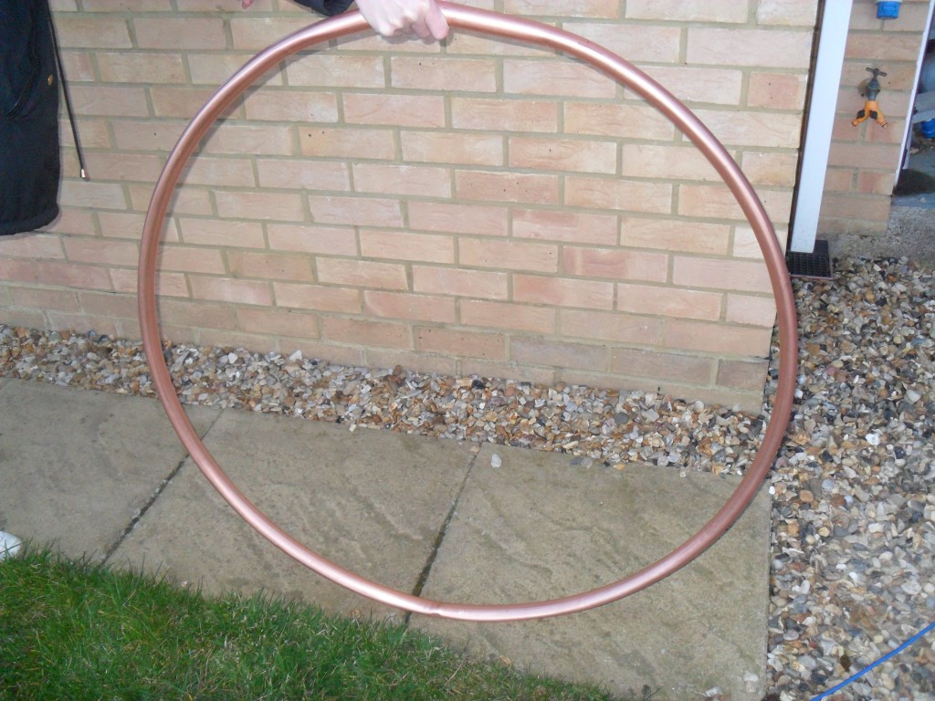 Loop held by my very able other half.