SWR of Inverted ‘L’

Their is a great saying that ‘if it ain’t broke don’t fix it’, I was reading about the optimal (link to random length article) length of antenna wire, my overall wire length is 30m rather than at one of the optimum lengths specified in the link, one of the indicators apparently was if the auto-tuner tuned to perfectly, then it is not optimized for all the bands that the tuner can tune to.

According to the article, my antenna length should be 25.6m, so I loped 4.4m off the end and gleefully went to the shack to see what a dramatic change this will have made, well it used to tune on 80m and now it doesn’t 🙁

The ladder came back out as did the soldering iron and heat shrink, I now have it back to as it was and I won’t make that mistake again!

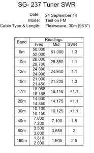
The table shows the results of the SG-237 tuning a 30m inverted ‘L’ wire at 6m above ground:

SWR Tuned Readings
SWR Tuned Readings

Lesson learned or is it now Lesson identified.

Pt 4 Longwire Installation – Final

This is the final part in the installation journal, the first bit was to mount the end bracket which secures and terminates the antenna wire to the side gable at the front of the house, I used the ‘T’ from a galvanized TK type bracket, the one used was 24″ in length and secured to the masonry by 2 x 10mm expanding shield anchors.

To fit the insulator to the ‘T’ bracket I bent a small length of M6 threaded stud bar round a scaffold pole, to enable the insulator to slide of the exposed threads of the stud, I slid the braid from a length of coax over it and secured that with helleman sleeves at each end.

2014-09-13 04.38.46 (Medium)

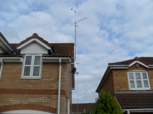
The existing TV pole and brackets were removed and the ‘T and K’ brackets were replaced, as were the securing fixings and pole brackets, this TV Pole also support the Weather Station anemometer and Direction sensor, so this was the reassembly order:

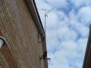
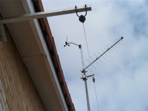
Nipped the pole up in the bracket and inserted the wind & direction sensor and pole into the top of TV pole and secured with machine screws, the pole was then pushed up slightly to allow me to add a log periodic TV aerial, the reason for replacing the existing TV aerial was to reduce windage loading on the pole.

The cables for the sensor and TV aerial drop within the pole exiting at the bottom before using conduit to pass through the wall.

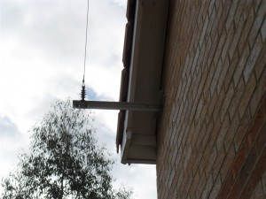
Below the aerial is a bracket which secures a small length of pole at 90 degrees to the main pole, this has pulley’s which enable me to lower the insulator for maintenance.

2014-09-13 04.38.17 (Medium)

The pulley parachord is secured with a halyard:

2014-09-13 04.38.31 (Medium)

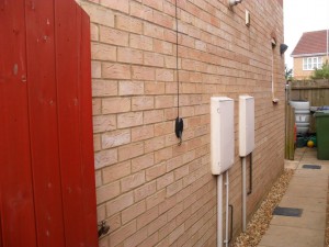
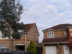
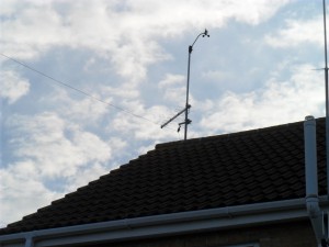
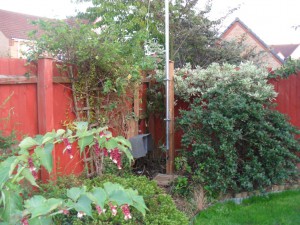
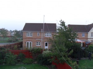
Couple of pictures which show different views of the antenna wire up:

2014-09-13 04.37.34 (Medium)

2014-09-13 04.37.57 (Medium)

2014-09-13 04.39.04 (Medium)

SAM_5184
The mod to this arrangement will be to replace the parachord with Dacron cord as I believe this is a more robust cord against the elements including UV.

Modifications to Wind & Direction Height

Disabled the wind and speed sensor at 10:48 to completely disconnect the cable and drop the aerial pole, the purpose was to add height giving greater accuracy by placing the sensor above the TV aerial, this will also stop the birds sitting on the TV aerial and pooping on it.

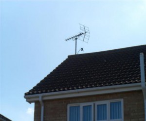
This shows the original setup.

SAM_4338 (Small) (Medium)

The new configuration shows the sensor has been lifted 1.5m by sliding a smaller diameter pipe into the main pole, shimming it to fit before being secured by tapping two M6 galvanized roofing bolts, to reduce the overall windage on the pole I have replaced the existing TV aerial with a smaller footprint.

2014-09-13 05.32.56 (Medium)

Sensor reconnected and working satisfactorily same day at 16:45.

Pt 3 Longwire Installation

Planning permission was granted today (10 Sept 2014 –  Ref:N9ZIWLHE01U00 ) for the installation of the 6m pole and longwire, in preparation I had mounted the 100mm x 100mm post and drilled the holes ready for the fixing saddles, this is a photo journal of the antenna install, this will be updated as each part is added.

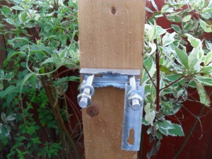
Saddle secured to post using 10mm stainless steel stud, on the reverse of the post is an additional saddle to spread the load on the studs and to prevent any ‘pull-through’.

2014-09-08 19.12.05 (Medium)

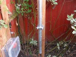
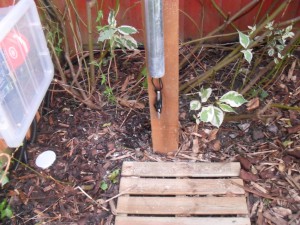
Pole secured to post using two saddles at 600mm centers, pole raised to insulate it from ground.

2014-09-10 06.57.12 (Medium)

Paracord threaded down the inside of the pole and secured, this allows the insulator to be lowered for maintenance, the slack is pushed up inside the pole.

2014-09-10 06.57.02 (Medium)

Tension on the wire is applied by the shock cord fixed to a hook, to reduce friction wear on the cord it is threaded through a galvanized pulley.

2014-09-10 06.57.34 (Medium)

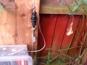
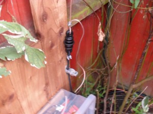
Side view of the pulley arrangement showing the shock cord fixing at the insulator and the clamp used to loop the flexiweave antenna wire.

2014-09-10 06.57.42 (Medium)

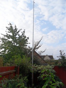
View of completed antenna post, eventually the bush will grow to ‘soften’ the post.

2014-09-10 07.00.37 (Medium)

Post up and antenna wire ready for high level fixings.

2014-09-10 18.20.39 (Medium)

Click for part 4

Weather Display and PSK Digital Master 780 Macro in Ham Radio Deluxe

I dabble with PSK31 within Ham Radio Deluxe Digital Master 780 (DM780) software, one feature I was particularly interested in was the ability to set various macros to automatically read and insert text for transmission from a file.

Weather Display is the software I use for my weather station and is unbelievably flexible in what can do, in my case I have it set to generate a text file of current weather conditions (temperature, wind speed, direction and rain fall) every 10 minutes.

Configuration – Weather Display

Setup >> Log Files
Main Log Setting switch – ON

Custom Log Settings >> Produce a custom log file is ticked
Update Frequency >> 10 minutes

Open explorer >> wdisplay folder >> webfiles

Within webfiles locate customtext and edit with the information you wish to send as the weather macro in DM780, I have this:

The temperature here is %temp%C with an average wind speed of %avgspd%mph from the %dirlabel%, Chatteris rain today%dayrn%mm

As I only have one customtext file set, I simply saved the changes without renaming the file.

The weather tags within the % determine the information that Weather Display inserts, a full list is in a text file named testags is within the webfiles folder.

What does all this do?

The result of all the above is that an existing text file named customtextout in webfiles is generated and overwritten every 10 minutes with the information previously requested in the customtext file.

Ham Radio Deluxe – DM780 Macro Setup

With DM780 open, Tools >> Macros

Double click on existing unticked macro – WX to edit
Right hand side of the screen is a tab called – Text from File – clicking on this inserts –

Weather here is temp is File-contents-go-here

I changed this to –

<his:callsign> de <my:callsign>
<his:firstname>
<file:\\HEWLETT-NN43CTX\webfiles\customtextout.txt><eof> k <stop>

Data from my weather station: www.chatteris.biz

Click OK to save the Macro ensuring that the enable box is ticked and exit from setup, the Macro called WX should show in the Info pane.

Note – As the Weather Display program and Ham Radio Deluxe are on separate computers I had to give the webfiles folder share permission on my home network, this is why the link to customtextout starts \\HEWLETT-NN43CTX\, if both programs were on the same PC, the path would be –

<file:C:\wdisplay\webfiles\customtextout.txt><eof>

If you need help, contact me via the contact form.

Updated 15 Nov 2022

73
Home Made 300w Dummy Load

Decided to make a dummy load as per the design of Ham AI4JI and incorporating ideas from a YouTube upload.

Link to AI4JI web site, this includes how to make the unit and also all the documentation showing how to take and interpret measurements in order to determine power output.

This YouTube video shows how to make a similar dummy load, the bit I took from this was the use of copper pipe.

https://www.youtube.com/watch?v=Gn0HaZMYzro

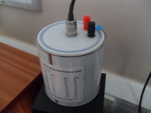
This is how mine turned out:
2014-09-05 19.40.07 (Medium)

Parts & Cost

Ebay for the following –

1 litre Empty Paint Mixing Tin £3.75
2 x 500ml White Mineral Oil £15.50
BAV21 250v Diodes (pack 10) £2.67 inc P&P
20 x 3w 1k 500v Metal Oxide Resistors £5.70

Radio Rally –

1 x SO239 Socket – Chassis Mount – Nut Fixing £1.00

Shack –

1 x 0.01uf 2kV Ceramic Capacitor
200mm offcut of 28mm Copper Pipe
Red & Black Terminal Posts

Total Cost – £28.62

The Mineral Oil was the most expensive part of this build, I could have used engine oil as the coolant but taking the overall costs into consideration, under £30 for a 300w capable Dummy Load is not too bad.

NOTE– 12 October 14 – Even through I sealed around the terminal posts and antenna outlet socket on the lid, I have found that the mineral oil is so viscous that it ‘wicks’ up the wires and finds the smallest escape, even when not in use.
At first I thought I must have overfilled the can somehow, but their is a 10mm gap between the top of the lid and the liquid level, so capillary action must be the cause just to let you know.