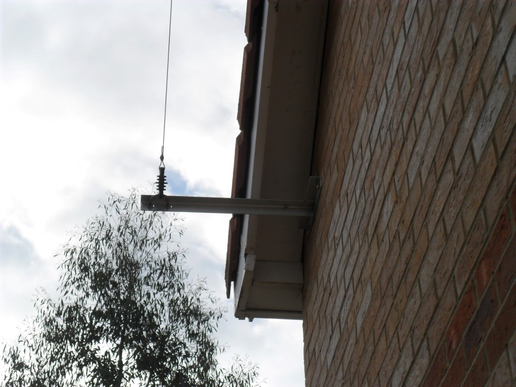
This is the final part in the installation journal, the first bit was to mount the end bracket which secures and terminates the antenna wire to the side gable at the front of the house, I used the ‘T’ from a galvanized TK type bracket, the one used was 24″ in length and secured to the masonry by 2 x 10mm expanding shield anchors.
To fit the insulator to the ‘T’ bracket I bent a small length of M6 threaded stud bar round a scaffold pole, to enable the insulator to slide of the exposed threads of the stud, I slid the braid from a length of coax over it and secured that with helleman sleeves at each end.
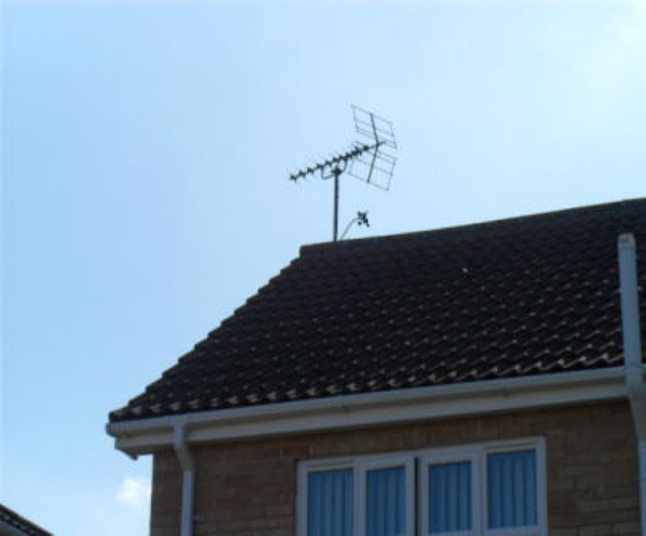
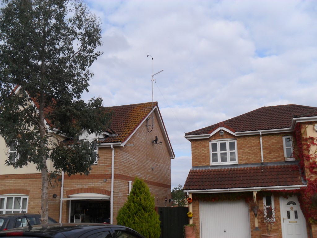
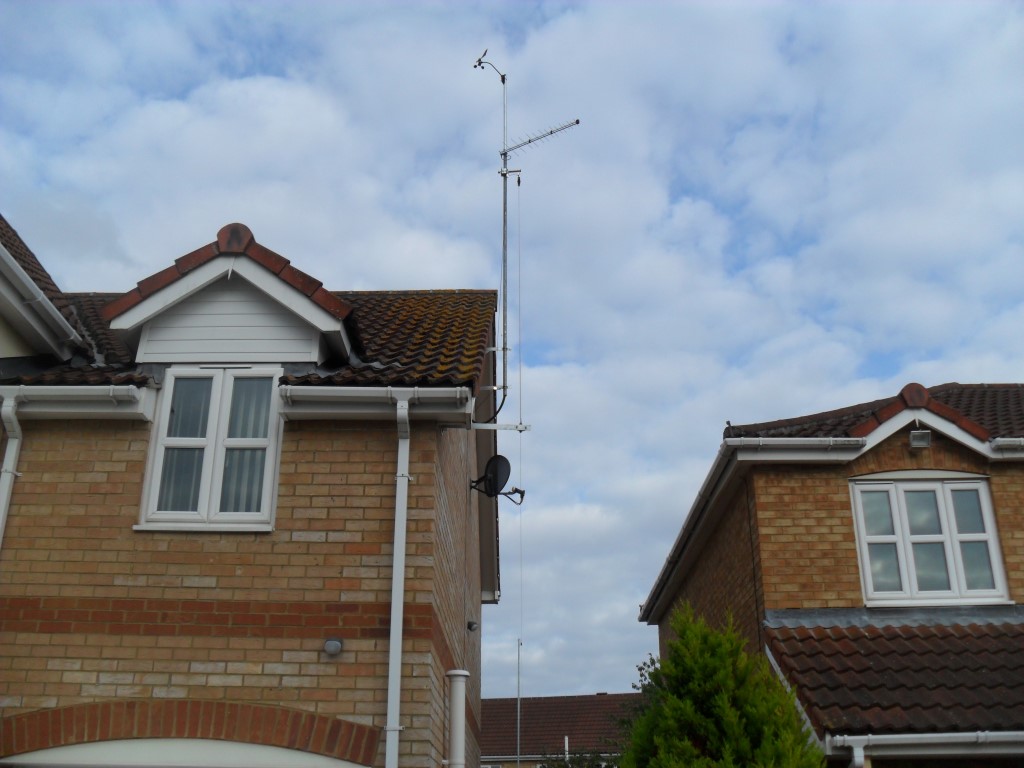
The existing TV pole and brackets were removed and the ‘T and K’ brackets were replaced, as were the securing fixings and pole brackets, this TV Pole also support the Weather Station anemometer and Direction sensor, so this was the reassembly order:
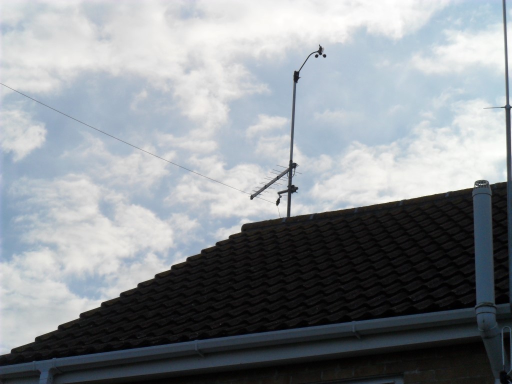
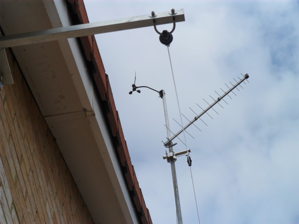
Nipped the pole up in the bracket and inserted the wind & direction sensor and pole into the top of TV pole and secured with machine screws, the pole was then pushed up slightly to allow me to add a log periodic TV aerial, the reason for replacing the existing TV aerial was to reduce windage loading on the pole.
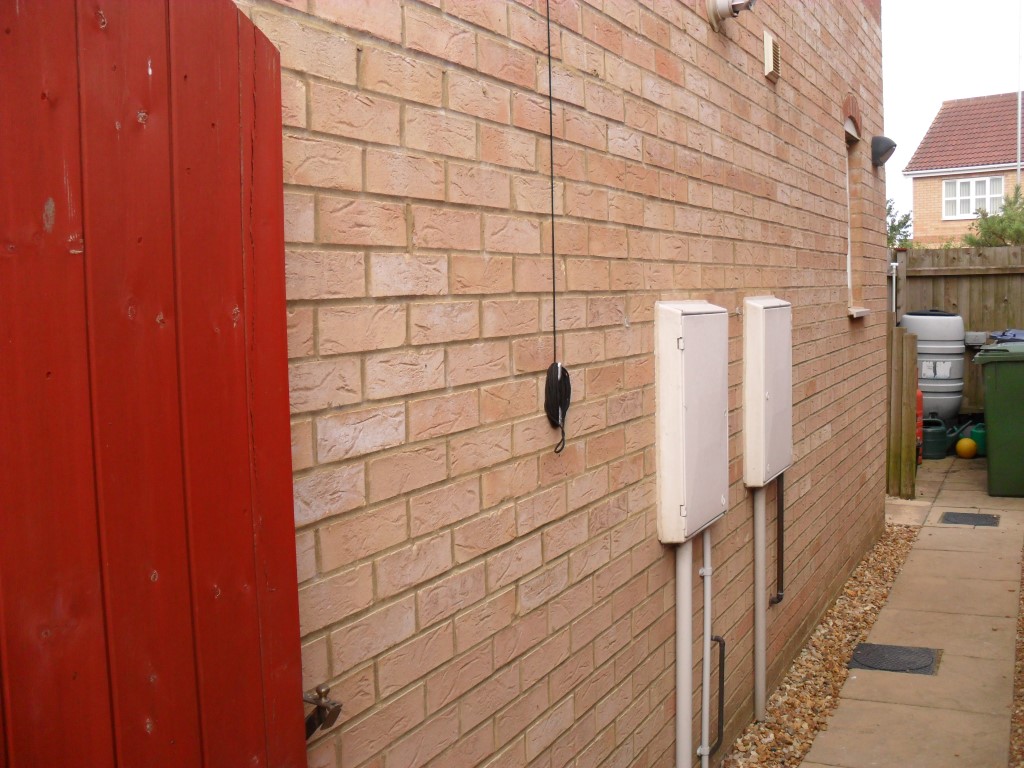
The cables for the sensor and TV aerial drop within the pole exiting at the bottom before using conduit to pass through the wall.
Below the aerial is a bracket which secures a small length of pole at 90 degrees to the main pole, this has pulley’s which enable me to lower the insulator for maintenance.

The pulley parachord is secured with a halyard:
Couple of pictures which show different views of the antenna wire up:
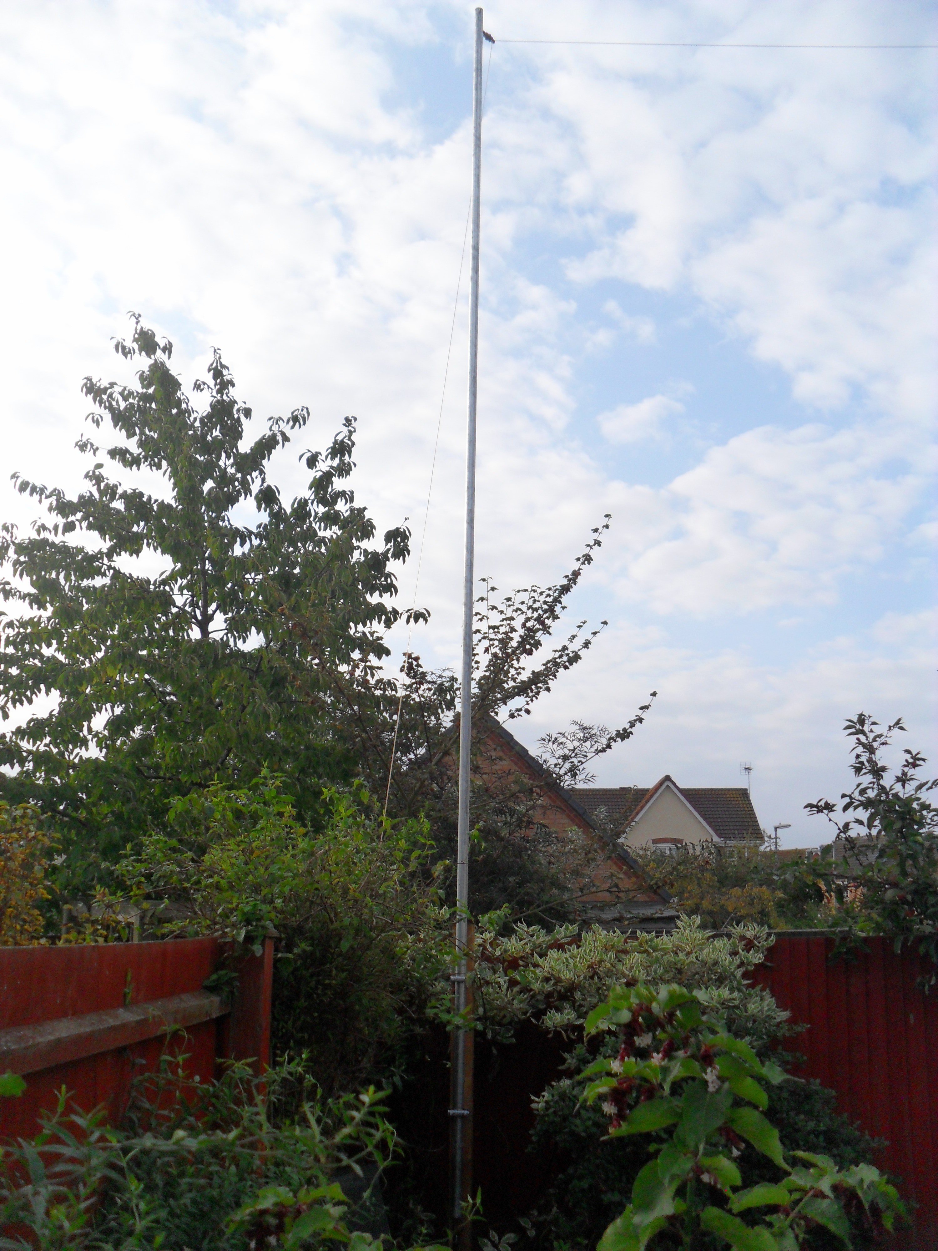
The mod to this arrangement will be to replace the parachord with Dacron cord as I believe this is a more robust cord against the elements including UV.