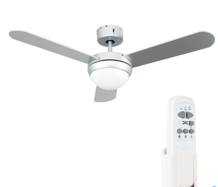
I have previously fitted a MiniSun 19500 fan and was very pleased with its performance considering the cost of the unit is quite low, however, I did have a few minor niggles relating to the lack of space in the base to fit the controller and the lack of lamp dimming.
The modifications I wanted to make were:
Dimming of the lamps as the fan is being installed in a bedroom
2 way light switching i.e. switching on/off from the wall or remote control
Note: The fan I was installing was new, but out of warranty, this modification will invalidate any outstanding warranties.
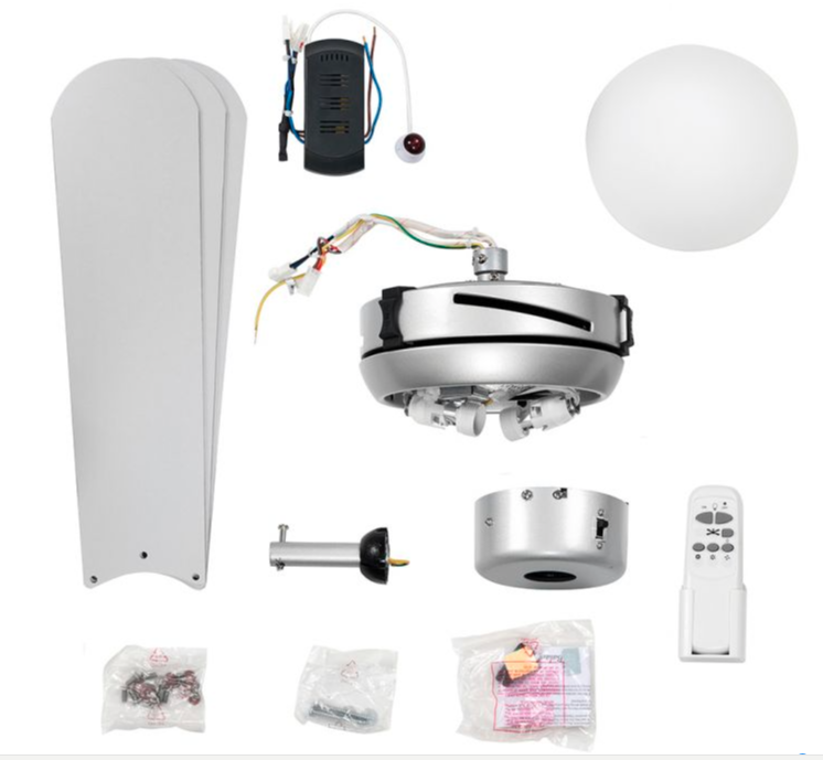
Included, but not shown above, are two, non dimmable 4W LED Golfball lamps (SES/E14).
For a standard installation, the controller uses plugs to connect to the fan motor and fan lights, with the controller then being crammed into the fan base, it is doable, but tight, so be warned.
Once power is applied, the light on/off and 3 motor speeds are selected and controlled by the remote control with the fans Infra-Red (I/R) sensor being adhered to the ceiling.
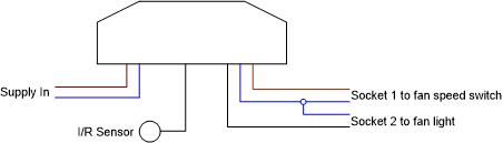
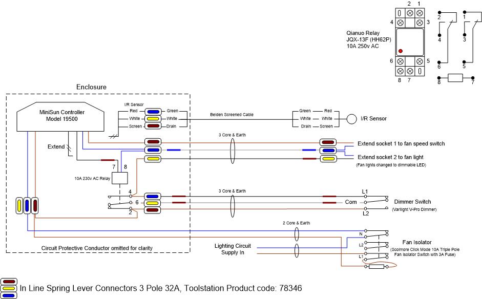
Drawing showing controllers inputs & Outputs
Modification
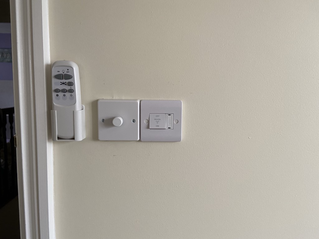
I needed to do a few enabling tasks before the ceiling fan was fitted, this meant the removal of the existing bedroom light and re-routing of the cables, also the installation of a 3 core & earth cable and Varilight V-Pro dimmer switch to replace the existing, non LED compatible dimmer switch.
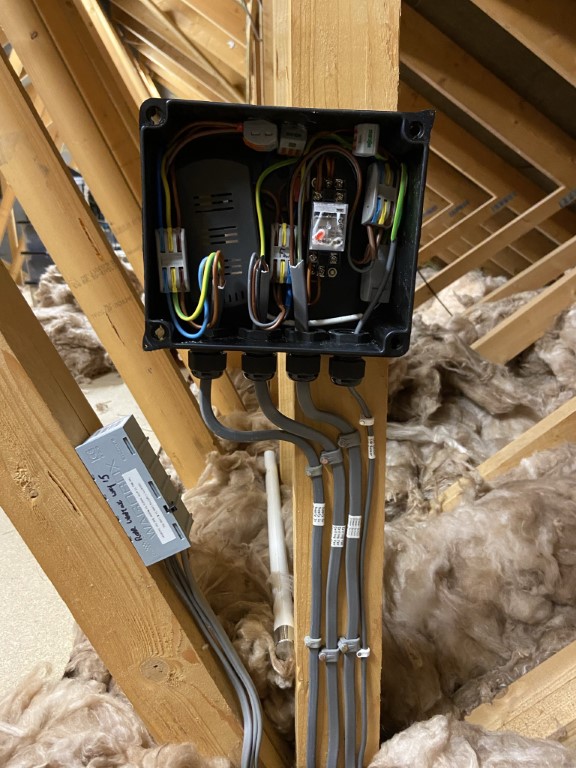
I also decided to fit a Scolmore fused isolator to make dead for maintenance, the finished arrangement is seen below:
The modification involves cutting off the controller plugs marked as 1 & 2, this allows the controller to be physically distanced from the base and reconnected using 3 core and earth cable.
The I/R Sensor wire is also cut and extended.
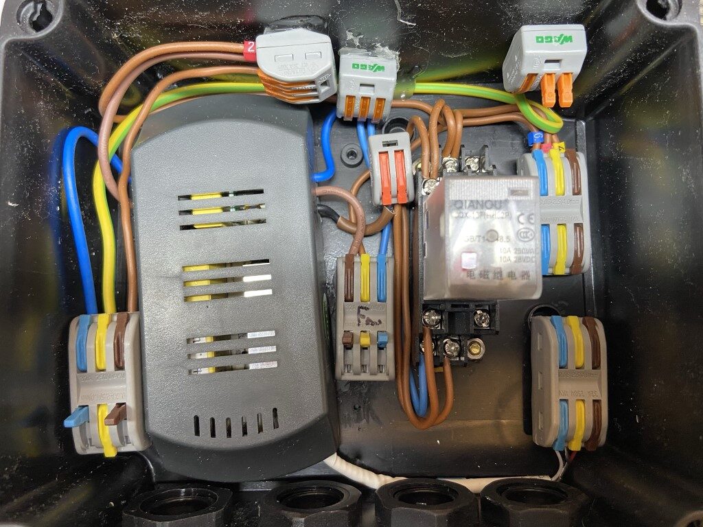
With the controller mounted in a suitable enclosure, a 230v AC relay is added, the relay is connected to the lamp output of the controller, and will be energized/deenergized by the light function button on the remote control.
Using the relay contacts, it is now possible to make the fan light into 2 way switching.
The 3 core & earth from the dimmer switch is wired across the relay contacts to enable the dimmer switch and remote control to behave as a 2 way switching arrangement with the added benefit of being able to dim the lights from the V-Pro.
Competed project, (lid removed for picture), the maintenance free junction box (JB) to the left of the unit is where the lighting circuit Loop In & Loop Out cables have been pulled back from the original ceiling rose, the supply to the controller is from this JB via the fused isolator.
My central heating system has 13 radiators with 12 having Thermostatic Radiator Valves (TRV), and I decided a couple of years ago to replace the existing wax capsule TRVs with intelligent Hive ones which I did.
Stock Honeywell TRV Head
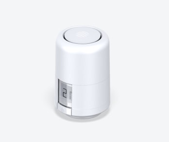
Hive Intelligent TRV replacement head
Installation of the Hive TRV was very straightforward, the existing heads are removed by unscrewing the knurled nut and the Hive supplied adapter is screwed into place on the valve body, the Hive TRV then screws to this and using the App is enrolled onto the heating system.
Hive TRVs have picked up negative reviews, I think this was due to launching the product before it had been fully beta tested, that said, most of the wrinkles have now been ironed out and I enjoy the benefits individual radiator temperature control and scheduling gives me.
My main issue has been that the Hive TRVs, which are controlled via a smartphone app, and this keeps requesting that the TRV’s need calibration, which I have put down to the age and condition of the existing radiator valves.
I could temporarily free sticking valve pins by ‘tapping’ and adding oil or WD40, but they would always stick again, and they did look a bit mangy, also my boiler pressure was dropping very slowly over time and I put this down to TRV valve leaks, so it was time for action!
Honeywell VT15 TRVs
The TRVs installed when the house was built (circa 2002) are VT15:
Unfortunately the valve has no serviceable parts and therefore no replacement insert is available which is a nonsense to be honest, as it forces you to either buy a complete valve assembly with TRV sensing head or search for a vendor who will sell the valve body only.
After much searching, I found a seller on eBay of VT15 valve bodies only at £6.99 each, so I bought what I needed which is a lot cheaper than buying a complete assembly for £15 each and throwing half of it away.
I had no intention of changing the valve body on the radiator as it would only introduce more work and an elevated risk of leaks from pipework joints, only the insert needed to be changed, so when I received the valves the inserts had to come out.
I had to use a 19mm socket in an Impact Screwdriver to remove the inserts from the new valves as they are insanely tight, so make sure the valve is held tightly in a solid vice before trying this.
Fitting Inserts
After switching power off to the boiler, I drained the water out of the heating system, this was easy in my case as the downstairs radiators had drain valve lockshields.
After removing the Hive TRV head, you can see the hexagonal head of the valve insert, using the Impact Screwdriver, the old insert was swiftly removed and the new insert fitted and carefully tightened with a 19mm ring spanner.
As the insert uses ‘metal- to metal’, mating face with the valve body to form a seal, I used V2-Plus jet lube jointing compound on the threads and joint face as a precaution against leaking.
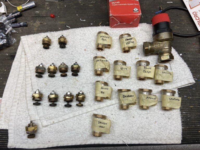
Removed inserts from the heating system.
I changed 11 inserts, on investigation 1 was OK, 10 were sticking or stuck in the closed position and of the 11, 7 showed signs of leaking.
While the system was drained I changed the Automatic Bypass Valve (ABV) for a better quality Honeywell DU145, although my boiler has an inbuilt ABV for boiler protection, it is prudent to have one installed with TRVs as the external ABV is designed to maintain a minimum pump flow rate through the boiler as the individual radiator TRVs close and to manage boiler over-run when zone valves close, rather than ‘dead heading’ the pump forcing the boiler ABV to open.
When all the inserts and the ABV was fitted, Fernox F1 inhibitor was added via Magnaclean filter chamber and the system filled with water, circulated and vented.
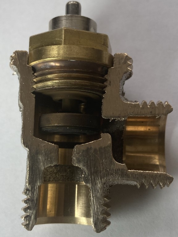
Not being a plumber, I decided to cut open a TRV valve body to see how it work and where it fails.
Jointing paste was used on the threads and contact face of the insert just in case of a bad seal
Insert Operation.
Water from the heating system enters at the bottom of the valve body, as the valve plunger is away from the valve seat (room asking for heat), water will pass and exit to the radiator.
If the pin on the top of the insert, (which is under spring pressure to keep the plunger lifted), is slowly pressed down, this will begin to restrict the water flow to the radiator as the plunger lowers into the valve seat, eventually closing the central heating water off completely to the radiator.
The job of the TRV head is to push down on this pin based on the rooms ambient temperature.
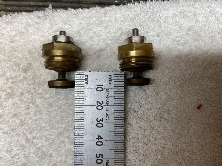
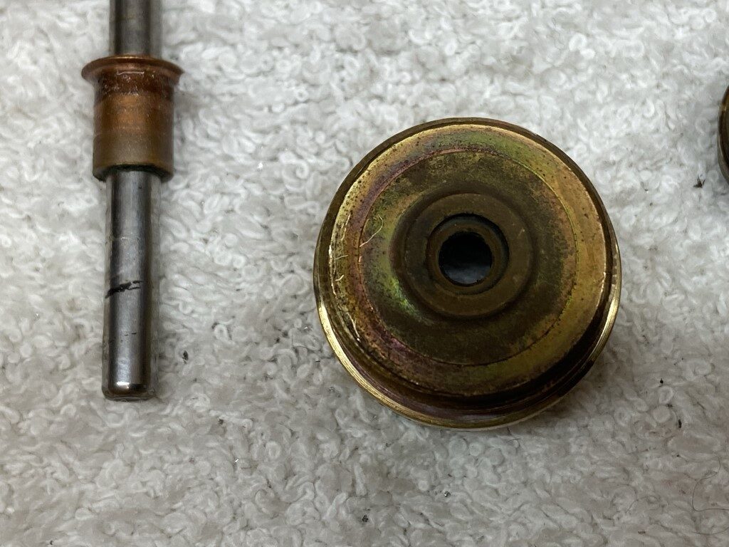
The movement of the pin is not very much at all :
The plunger on the left is stuck in the lowered position, the one on the right is OK as the internal spring has overcome friction and lifted the plunger.
So what’s inside an insert?
Bottom View
Top View
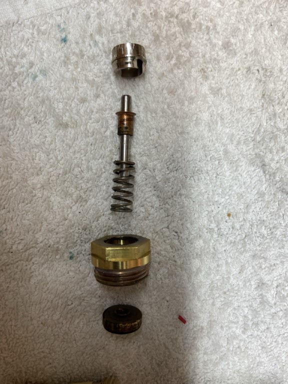
Starting at the bottom of the insert, this is in contact with the central heating water, the first part is the plunger which has a disk of rubber, copper riveted to it, this forms the watertight seal when the plunger is pushed fully down into the seat of the valve body.
The plunger is pushed tightly onto a stainless steel pin allowing the pin to raise and lower the plunger, the pin passes through a rubber seal in the body of the brass insert.
With the pin in the body, a spring sits over the pin and a copper ferrule holds the spring in place.
The last part is the stainless steel collet which is held in place by a ribbed design, locking into the brass body when pushed in.
The action of locking the collet in to the body, compresses the spring, forcing the copper ferrule to seat against the underside of the collet and lifting the pin to the correct height to enable the plunger to be lifted clear of the valve body seat.
Where are the problem areas?
The majority of my problems were due to the pin sticking, the root cause is where the pin passes through the rubber seal at the base of the brass insert body, and no amount of lubrication will get anywhere near it.
It looks like the rubber seals have age hardened due to being subject to wide temperature variations over time, eventually the seals friction against the pin overcomes the springs lifting force.
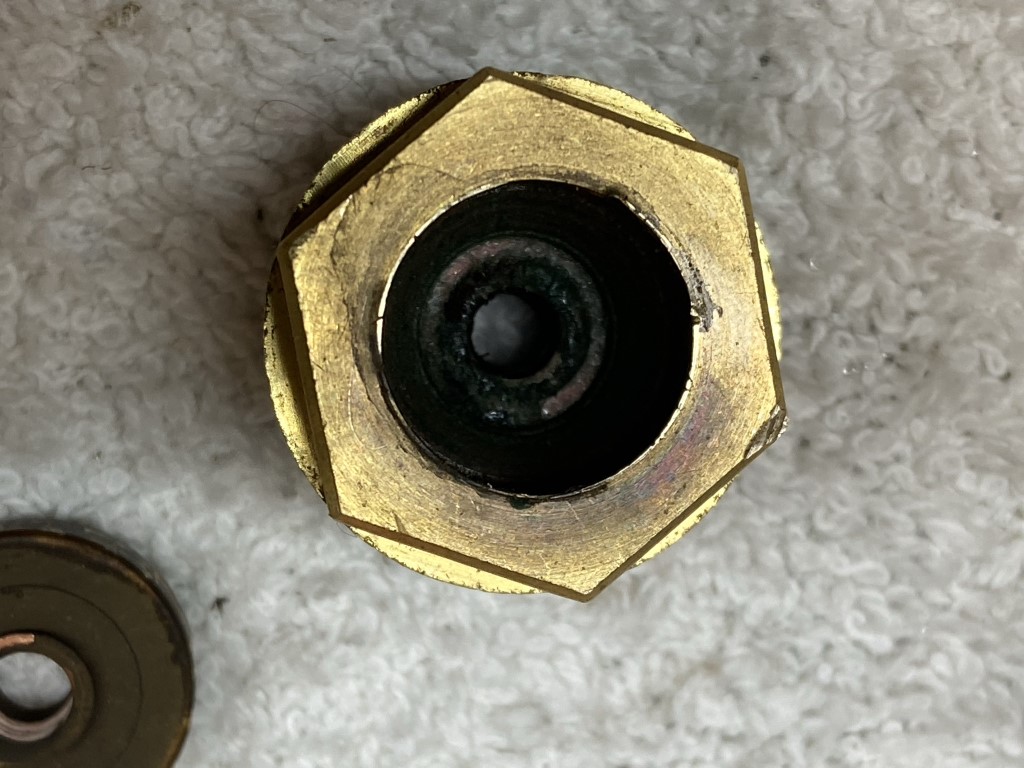
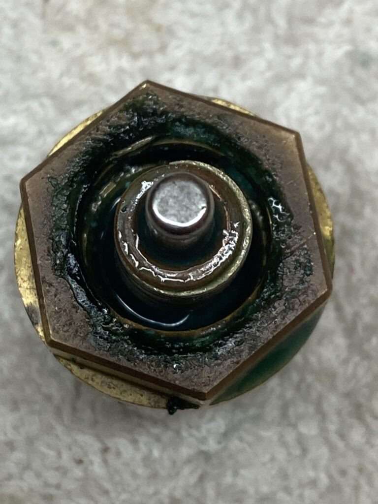
Obvious sign of water seepage into the insert cavity.
As a result of the pin seal ageing, system water creeps into the insert cavity, making its way past the locking joint of the collet/body or collet/pin, manifesting as discolored caking at the interface, this is an area for ‘weeping’ as the gunge is damp and therefore a point where system pressure is lost.
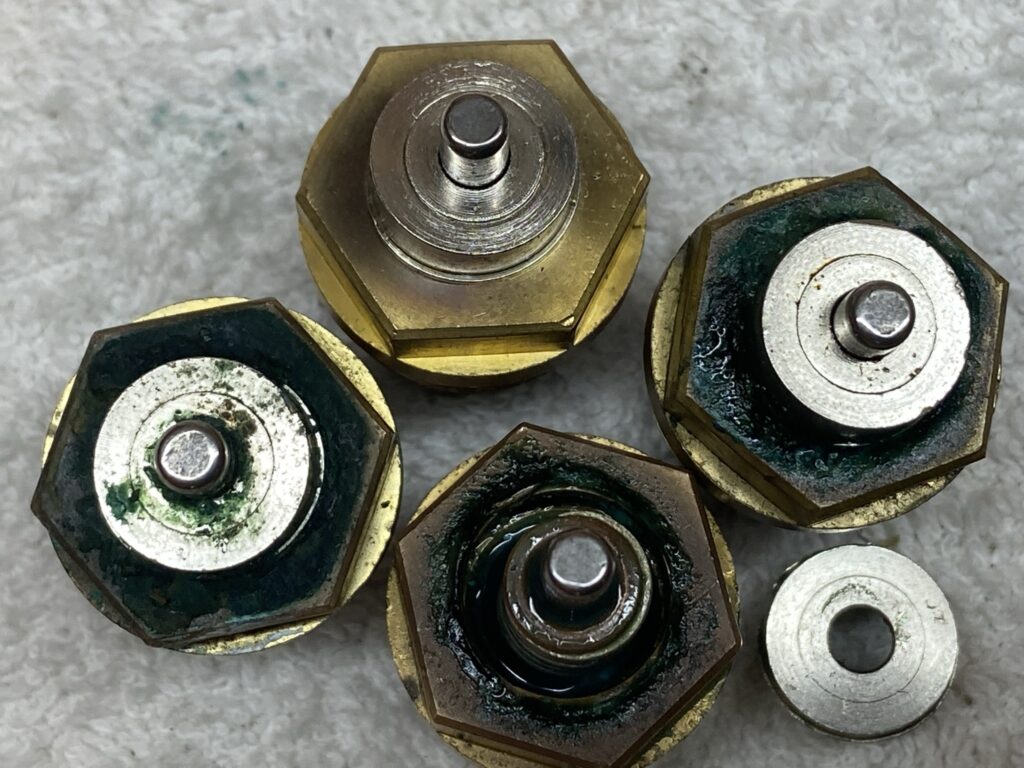
This picture says it all, the top insert shows how a good one should look, with the pin freely moving when pressed down using an upturned spoon.
To Sum Up
Don’t waste your time lubricating or tapping TRV pins like I did, the pin is sticking at the seal and no amount of lubricant will fix it 🙁 .
If the pin sticks or gunge is evident, you are only putting off the inevitable valve change, a plumber can do what I did a lot quicker and in some cases without draining the system, however, it is a DIY job if your confident.
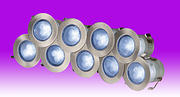
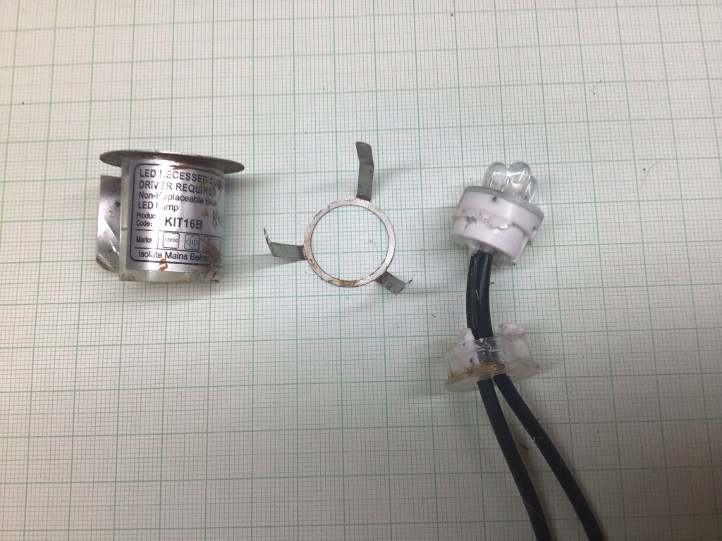
I bought two sets of the GL KIT16B garden walk over LED lights from TLC Electrical for my decking, each set comprises of 10 LED lights and a 12v transformer, the cost of each kit was £31.40.
I had these installed for about a year but due to an electrical problem which caused an overvoltage, the lights stopped working.
The choice was to buy new kits or try and repair them 🙂
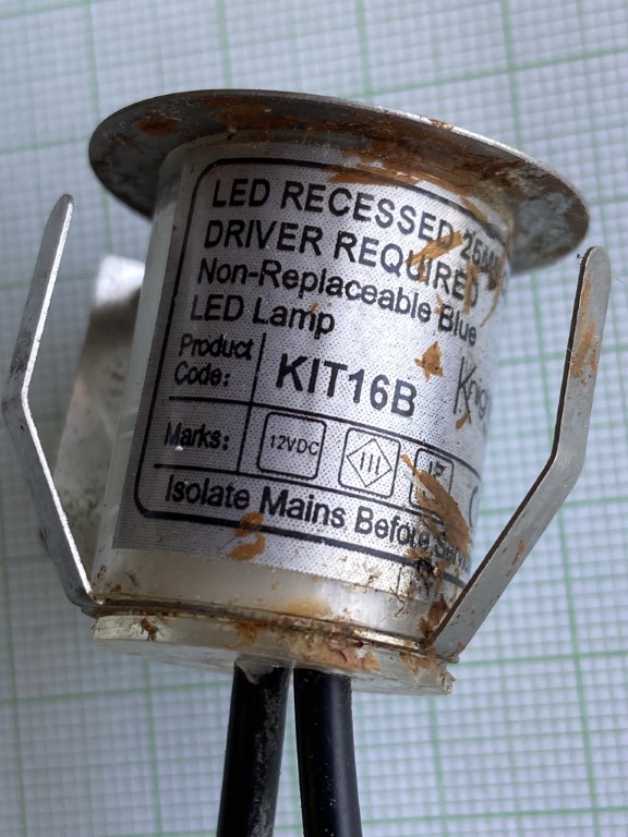
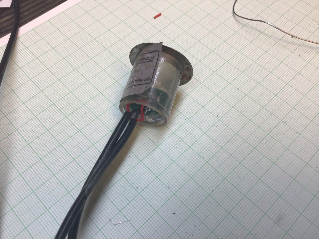
The case does say Non-Replaceable Blue LED Lamp and this turned out to be incorrect.
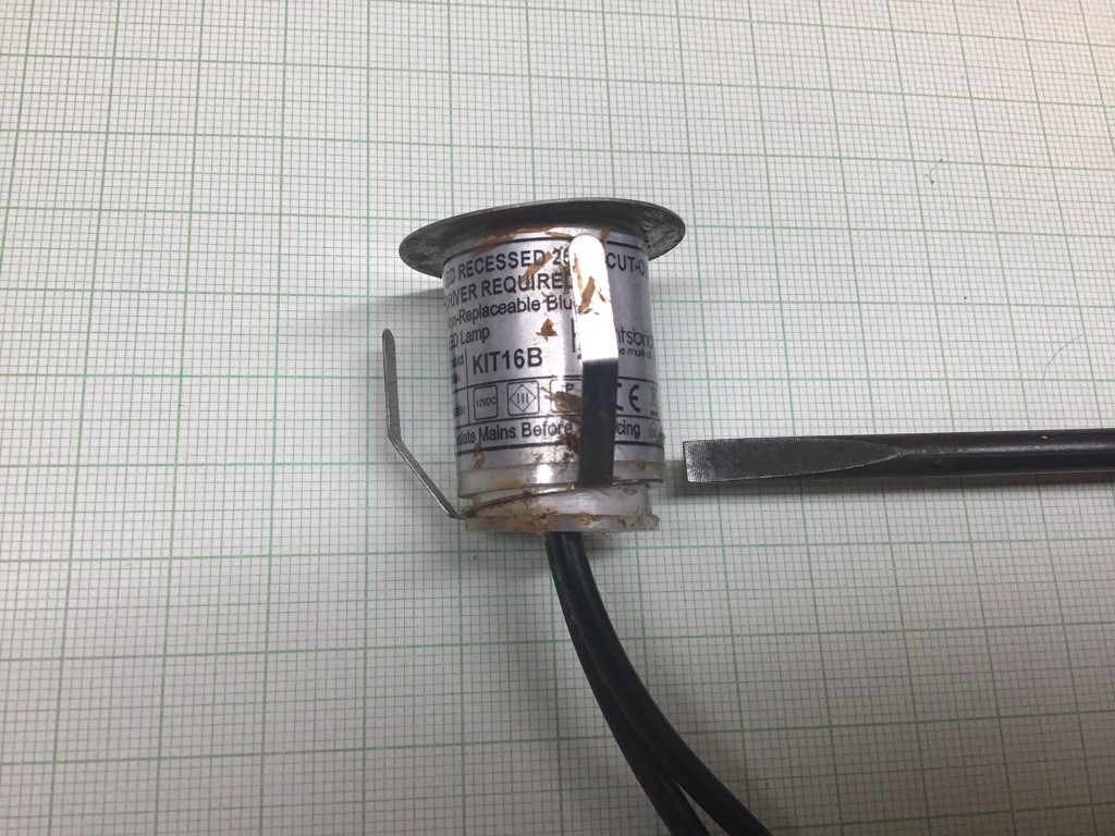
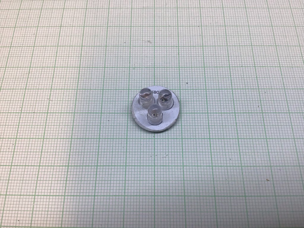
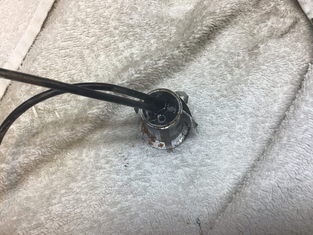
First job was to separate the base from the lamp body, it looks like they used an RTV (Room Temperature Vulcanizing) sealant. With gently persuasion using a screwdriver blade, the body came apart.
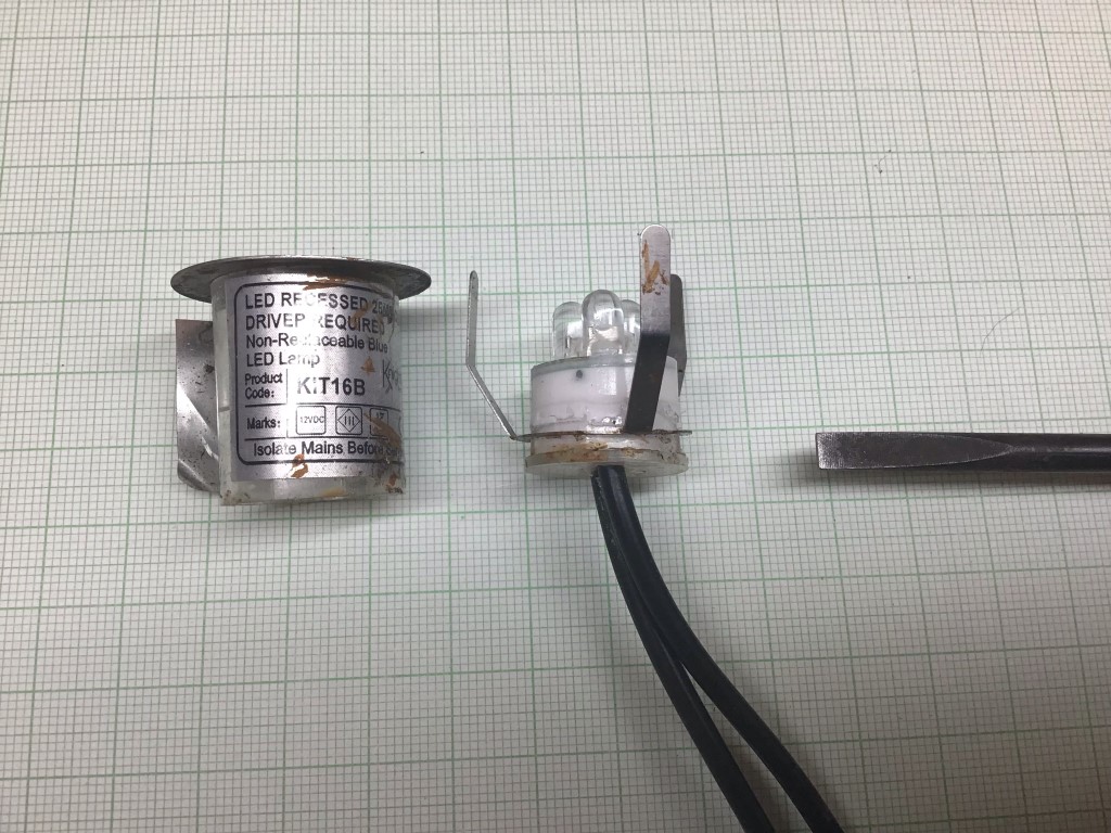
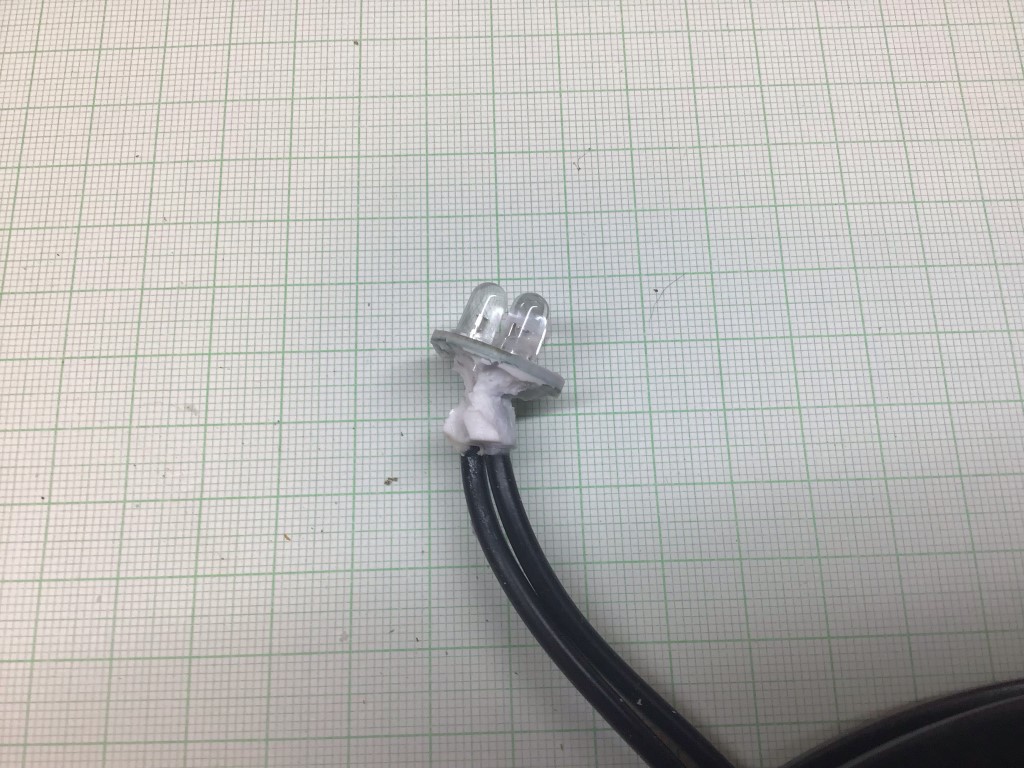
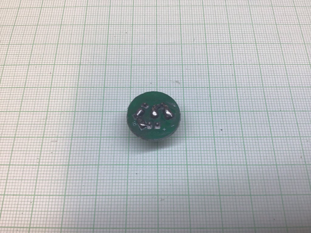
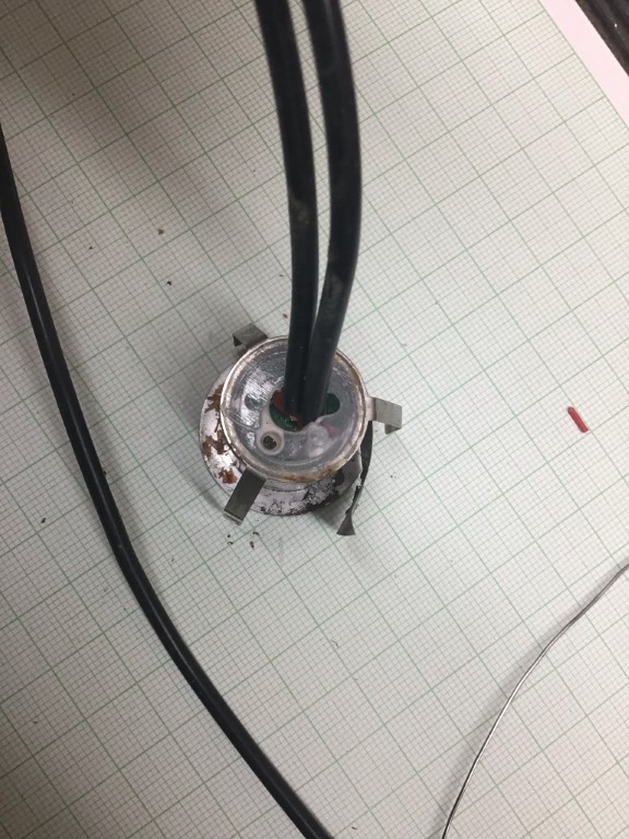
In order to get at the circuit board, base of the lamp need to be separated, this was done by simply pulling it apart.
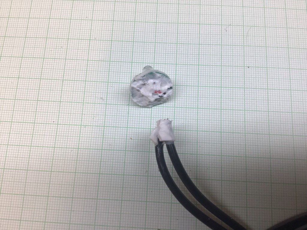
I got a fair bit of sealant of by using my fingers, the next step was to cut off the cables allowing more access to the PCB.
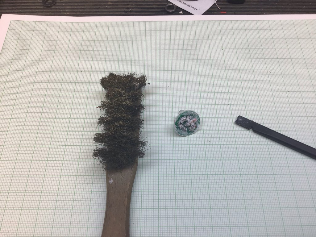
I used a Spudger to scrape off as much as I could before using a Brass brush.
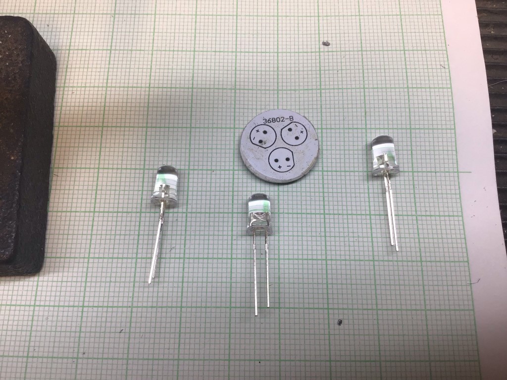
The PCB was now nice and clean ready to unsolder the duff LED’s and SMT resistor which was open circuit.
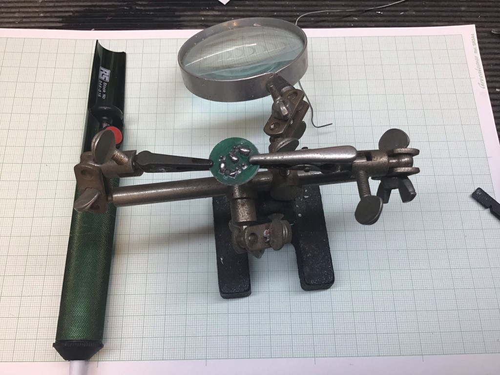
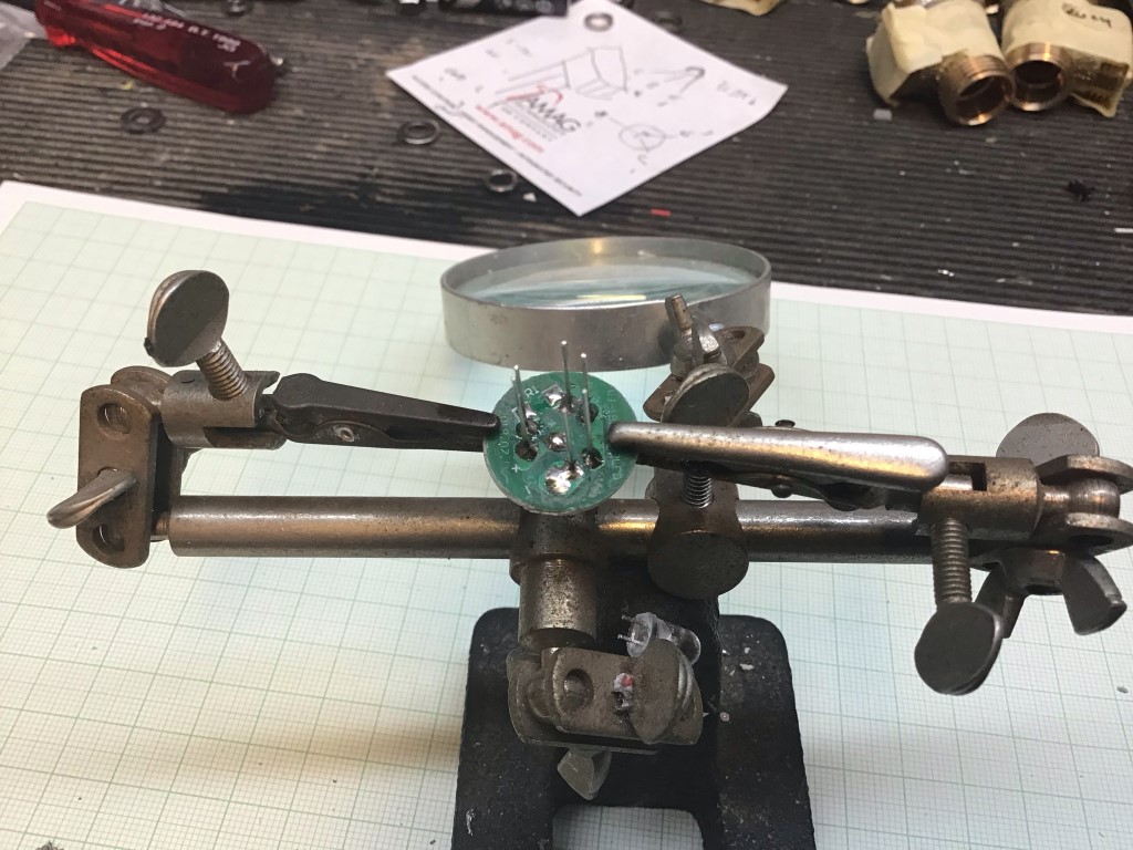
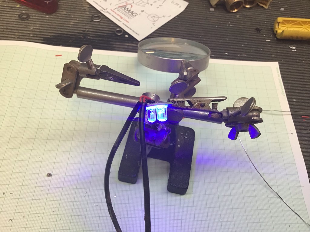
I’ve had this Helping Hand for more years than I care to remember and is perfect for this type of work.
All the LED’s have been unsoldered, I used a solder pump for this, all that is left is the damaged resistor to remove.
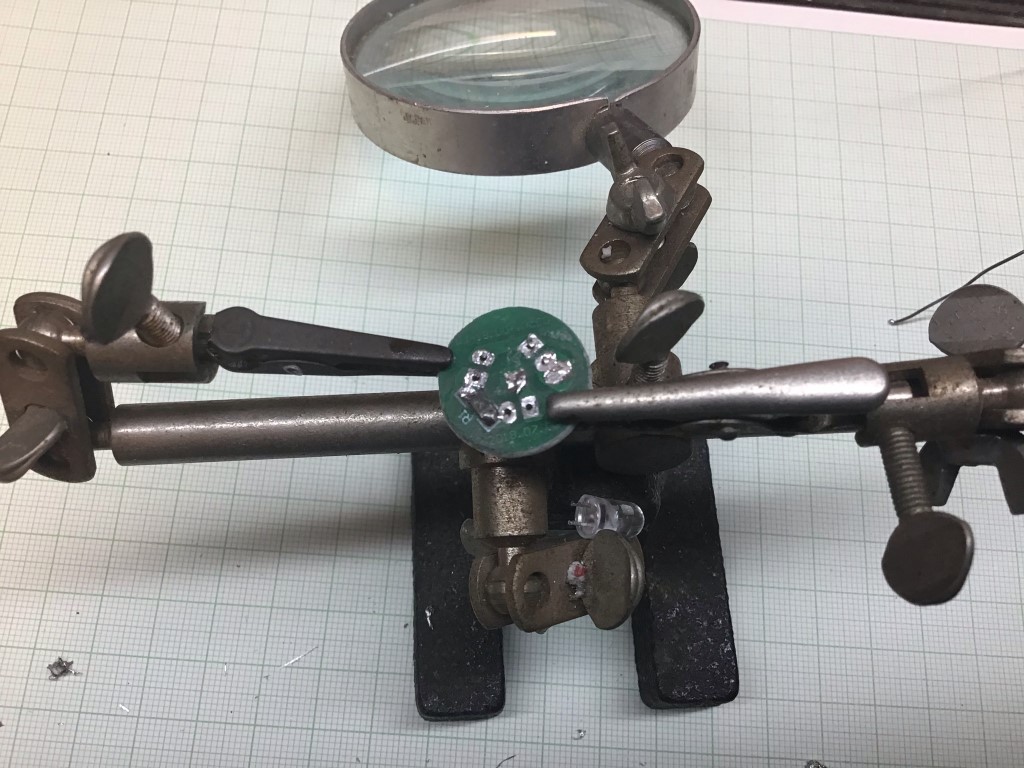
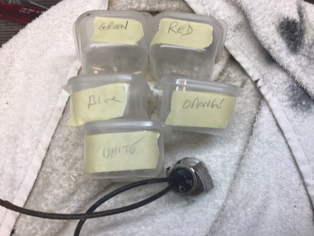
New LED’s ready to solder in, as you can see the PCB is printed with the orientation of the LED legs and LED body.
In the picture above I was soldering in Blue LED’s, however, I took the opportunity to change the colour in 8 of the lights to green to match the other garden lights.
LED’s, soldered in ready for the legs to be cut off and the resistor to be fitted.
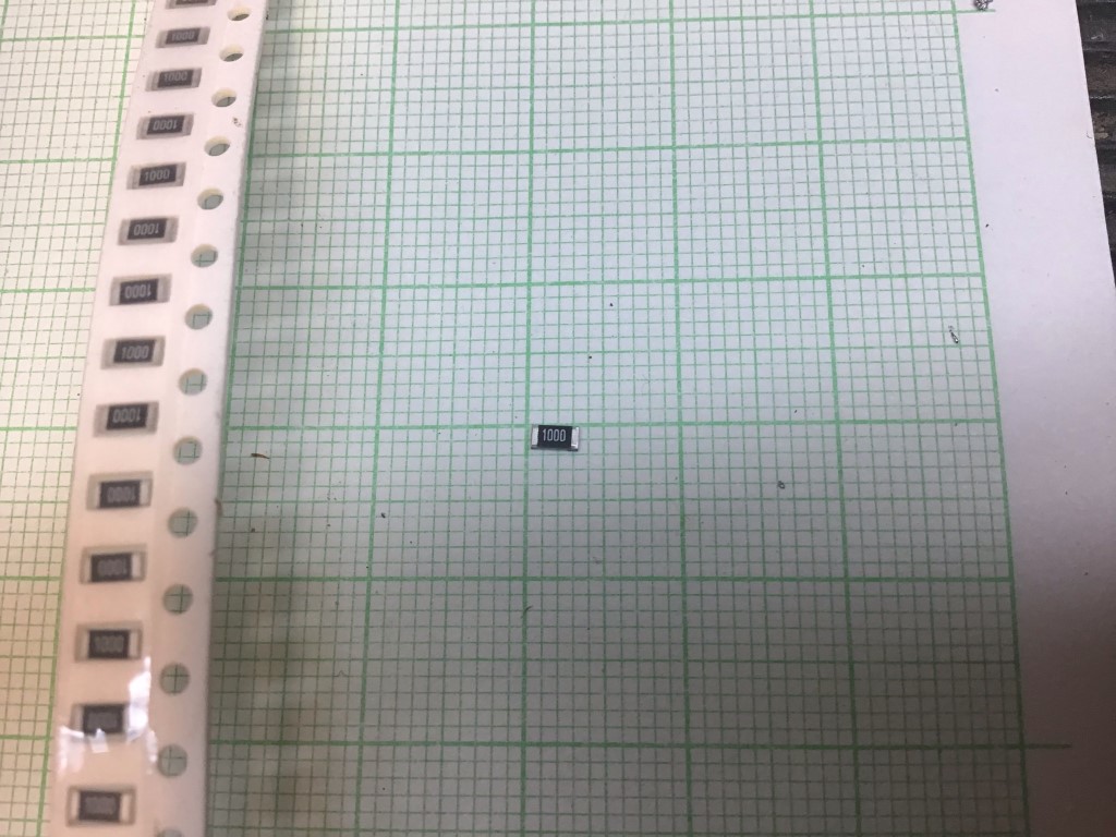
The resistor needed was a 100 Ohm Type 1206 Surface Mount Device.
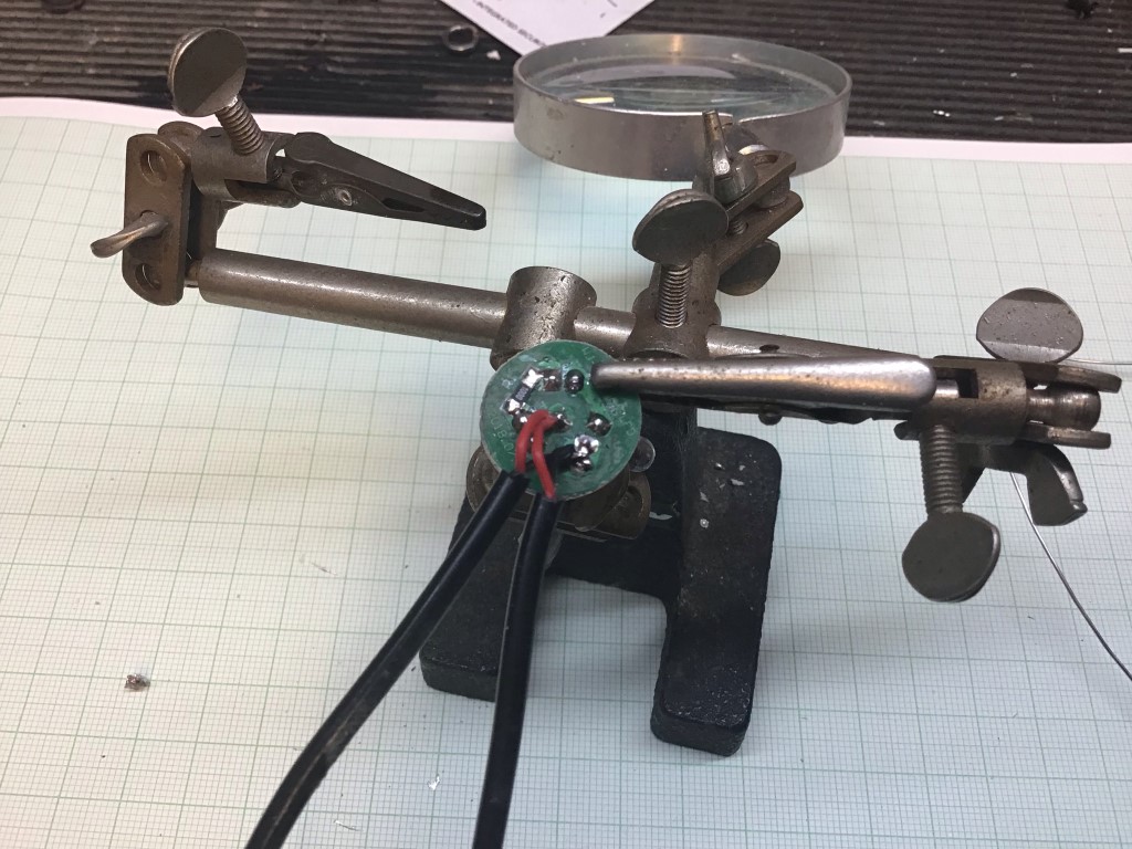
Once the resistor was in, the connecting cables can be reattached.
A quick test before reassembly.
With the PCB pushed back inside the light body, it’s important not to forget the holding clip for the next stage.
All pushed back into place ready to be sealed up.
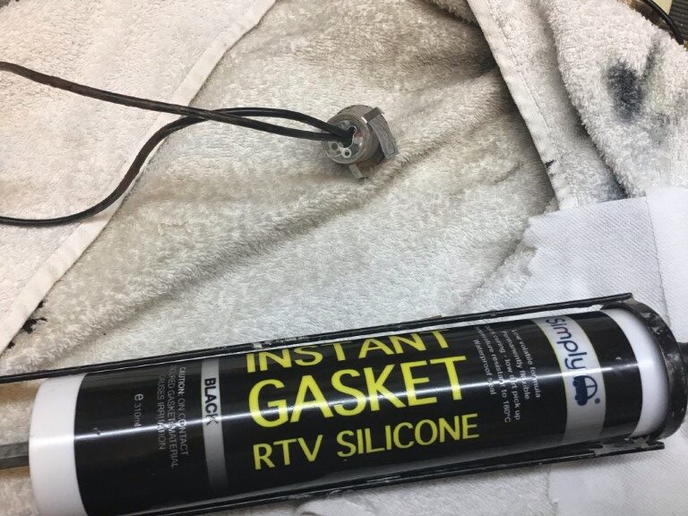
I used RTV Gasket silicone which cost £3.32, this is prefect as a potting compound.
Completed refurbished LED light, total time from start to potting is about 10 minutes.
The LEDs are 5mm and are very cheap off eBay, I could have fitted a number of different colours, but Blue and Green was fine, Knightsbridge only make Blue, White and Warm White in this model range, but don’t let you put this off after seeing this blog.
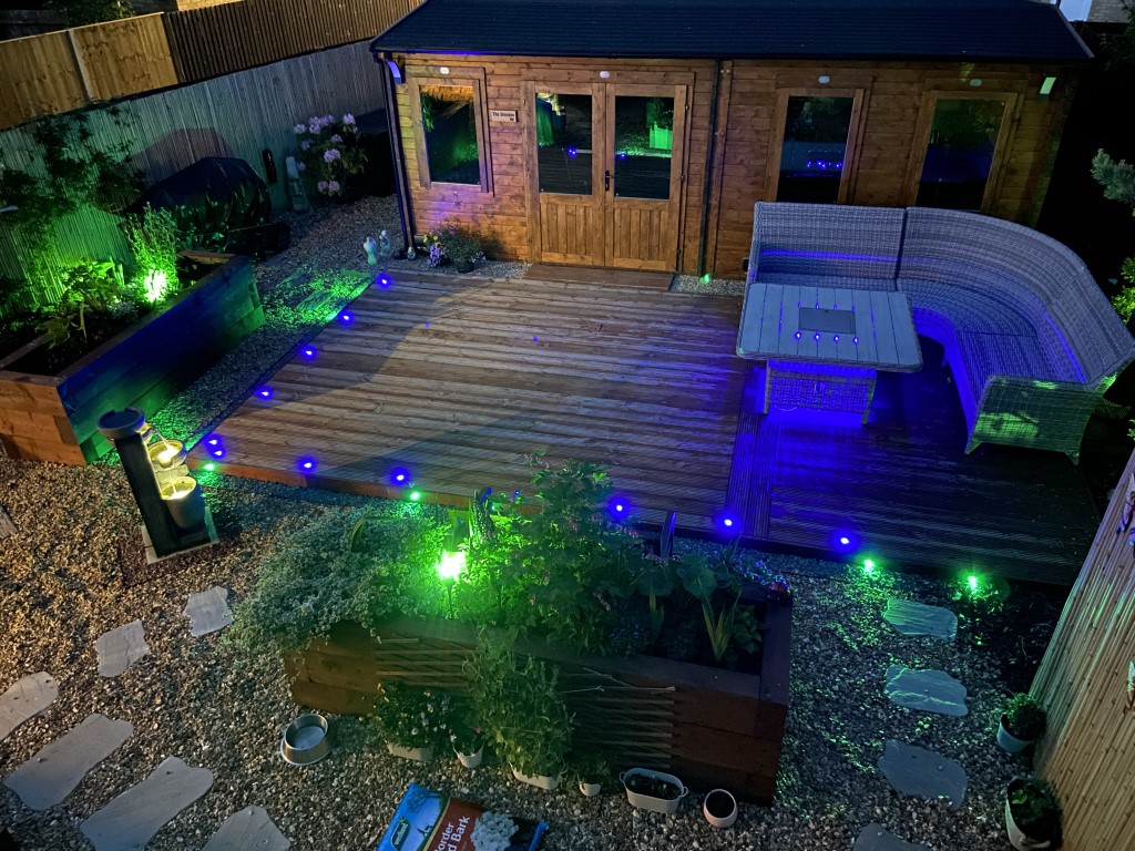
Finished look with the green deck lights pointing outwards illuminating the paths from the deck, really pleased with the finish and how easy and cheap it was to do.
A blog about stuff that interests me or I have done.
We use cookies on our website to give you the most relevant experience by remembering your preferences and repeat visits. By clicking “Accept All”, you consent to the use of ALL the cookies. However, you may visit "Cookie Settings" to provide a controlled consent.
This website uses cookies to improve your experience while you navigate through the website. Out of these, the cookies that are categorized as necessary are stored on your browser as they are essential for the working of basic functionalities of the website. We also use third-party cookies that help us analyze and understand how you use this website. These cookies will be stored in your browser only with your consent. You also have the option to opt-out of these cookies. But opting out of some of these cookies may affect your browsing experience.
Necessary cookies are absolutely essential for the website to function properly. These cookies ensure basic functionalities and security features of the website, anonymously.
Cookie
Duration
Description
_GRECAPTCHA
5 months 27 days
This cookie is set by the Google recaptcha service to identify bots to protect the website against malicious spam attacks.
cookielawinfo-checkbox-advertisement
1 year
Set by the GDPR Cookie Consent plugin, this cookie is used to record the user consent for the cookies in the "Advertisement" category .
cookielawinfo-checkbox-analytics
11 months
This cookie is set by GDPR Cookie Consent plugin. The cookie is used to store the user consent for the cookies in the category "Analytics".
cookielawinfo-checkbox-functional
11 months
The cookie is set by GDPR cookie consent to record the user consent for the cookies in the category "Functional".
cookielawinfo-checkbox-necessary
11 months
This cookie is set by GDPR Cookie Consent plugin. The cookies is used to store the user consent for the cookies in the category "Necessary".
cookielawinfo-checkbox-others
11 months
This cookie is set by GDPR Cookie Consent plugin. The cookie is used to store the user consent for the cookies in the category "Other.
cookielawinfo-checkbox-performance
11 months
This cookie is set by GDPR Cookie Consent plugin. The cookie is used to store the user consent for the cookies in the category "Performance".
CookieLawInfoConsent
1 year
Records the default button state of the corresponding category & the status of CCPA. It works only in coordination with the primary cookie.
PHPSESSID
session
This cookie is native to PHP applications. The cookie is used to store and identify a users' unique session ID for the purpose of managing user session on the website. The cookie is a session cookies and is deleted when all the browser windows are closed.
viewed_cookie_policy
11 months
The cookie is set by the GDPR Cookie Consent plugin and is used to store whether or not user has consented to the use of cookies. It does not store any personal data.
Functional cookies help to perform certain functionalities like sharing the content of the website on social media platforms, collect feedbacks, and other third-party features.
Performance cookies are used to understand and analyze the key performance indexes of the website which helps in delivering a better user experience for the visitors.
Analytical cookies are used to understand how visitors interact with the website. These cookies help provide information on metrics the number of visitors, bounce rate, traffic source, etc.
Cookie
Duration
Description
_ga
2 years
The _ga cookie, installed by Google Analytics, calculates visitor, session and campaign data and also keeps track of site usage for the site's analytics report. The cookie stores information anonymously and assigns a randomly generated number to recognize unique visitors.
_ga_92TJCVGJP2
2 years
This cookie is installed by Google Analytics.
_gat_gtag_UA_48800884_1
1 minute
Set by Google to distinguish users.
_gid
1 day
Installed by Google Analytics, _gid cookie stores information on how visitors use a website, while also creating an analytics report of the website's performance. Some of the data that are collected include the number of visitors, their source, and the pages they visit anonymously.
CONSENT
2 years
YouTube sets this cookie via embedded youtube-videos and registers anonymous statistical data.
is_unique
5 years
StatCounter sets this cookie to determine whether a user is a first-time or a returning visitor and to estimate the accumulated unique visits per site.
is_visitor_unique
2 years
StatCounter sets this cookie to determine whether a user is a first-time or a returning visitor.
sc_is_visitor_unique
2 years
StatCounter sets this cookie to determine whether a user is a first-time or a returning visitor.
Advertisement cookies are used to provide visitors with relevant ads and marketing campaigns. These cookies track visitors across websites and collect information to provide customized ads.
Cookie
Duration
Description
NID
6 months
NID cookie, set by Google, is used for advertising purposes; to limit the number of times the user sees an ad, to mute unwanted ads, and to measure the effectiveness of ads.
VISITOR_INFO1_LIVE
past
A cookie set by YouTube to measure bandwidth that determines whether the user gets the new or old player interface.
YSC
session
YSC cookie is set by Youtube and is used to track the views of embedded videos on Youtube pages.
yt-remote-connected-devices
never
YouTube sets this cookie to store the video preferences of the user using embedded YouTube video.
yt-remote-device-id
never
YouTube sets this cookie to store the video preferences of the user using embedded YouTube video.
yt.innertube::nextId
never
This cookie, set by YouTube, registers a unique ID to store data on what videos from YouTube the user has seen.
yt.innertube::requests
never
This cookie, set by YouTube, registers a unique ID to store data on what videos from YouTube the user has seen.