I’ve wanted to do a few tweaks to the home workshop for a while, and today I finally got round to it.
The easiest job was done first, this was to install an additional light fixture to house a Hive Smart Light, this has been added to the global Group ‘Lights’ in the Hive App, by the simple Alexa command ‘Lights On’ or Lights Off, all Hive lights and sockets with connected lights operate, this is really handy feature should we hear any noises in the night.
The light can also be turned on independatly via the Hive App or via interfaces to other Apps’ or IFTTT.
I bought a cheap and cheerful circular light fitting for the Hive light as it’s very easy to wipe clean. In the application I was using the hive light for, the lamp required an unswitched mains supply.
The besa box Tee above the Exocutor had the ‘loop in, loop out’ wiring for the suspended light, the new fixture was simply fed from permanent live from this and was up and running within 5 minutes.
The second job is something that I have wanted to for ages but the cost of the technology was prohibitive, until now!
The picture above shows my conversion of a garage into a workshop, this was done in 2007, after the walls were lined, the dado trunking and socket outlets were installed, you can make out that I have used Red and White sockets, the Red ones are not switched via a contactor, whereas the white ones are.
Operating any of the three ‘Emergency Off’ latching buttons, will disconnect the sockets and non Red fused connection units. A Red LED indicator by the bench illuminates when the Power to the sockets is ON.
The existing arrangement works fine , but I have always wanted an easy remote ‘power off’ ability, as I have had to check on countless occasions if I have left a soldering iron ON, my usual ‘gotcha’ is the compressor ‘kicking in’, in the middle of the night.
With the cost of internet enabled and Alexa compatable WiFi Smart switches coming down to a ridiculous price of £4.39, now was the time to make the addition of remote operation.
To the left of the change-over switch is the consumer unit feeding the Garage sockets via a 20A MCB, a 3A MCB is for the contactors control circuit via the latching stop buttons.
Cables fished in, Left side is the supply to the Sonoff, the Right side is the Sonoff’s switched output.
Sonoff connected and cables dressed in to consumer unit.
Completed job with Sonoff showing link to server established, before starting the work I configured the Sonoff in the house and enabled the power to be ON by default, once this was done I checked that it work in the Garage.
The configuration is very easy and the App is EWelink, also this is linked to Alexa, the image below is a screen shot of the EWelink App.
Update – 5 Jan 18, E-WeLink servers have failed this means that control of the Sonoff devices is not possible, no time given as to restoration of service 🙁
14 Jan 18 – Service back up and running and all Sonoff devices now working.
I have had an Amazon Dot for a while and use the interactive plugs and lights all the time, one of the plugs is for my Ham Radio PSU, so I have been looking for a relay interface which will work with the Amazon Dot, one of the key requirements is that the relays must be able to pulse on then off.
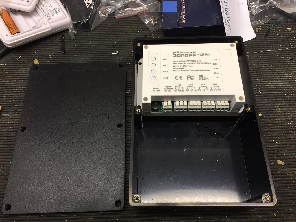
The Sonoff 4Ch Pro costs ~£25 and has 4 programmable relays including the ability to ‘inch’ a relay (pulse on then off), the reason this is important for me, is that it allows a momentary trigger to the PLC controlling my automated mast.
The Sonoff 4Ch Pro is well made and can be powered from either the mains or 5 – 24v DC, relays are all voltage free.
The Sonoff App is EWeLink and allows direct control of the relays from anywhere, this App is then linked to the Amazon Alex App to allow voice control of the relays,m if you want to use voice control from your smartphone, Reverb is good.
EWeLink App needs an account setting up, once this is done, follow the instructions to pair with your router. The default pairing LED flashing sequence did not work for me, I had to keep my finger on a relay button until the blue LED rapidly flashed and then followed the instructions.
Once paired, the blue LED remains steady, after a power down, WiFi locks within 20 seconds.
Sonoff Enclosure
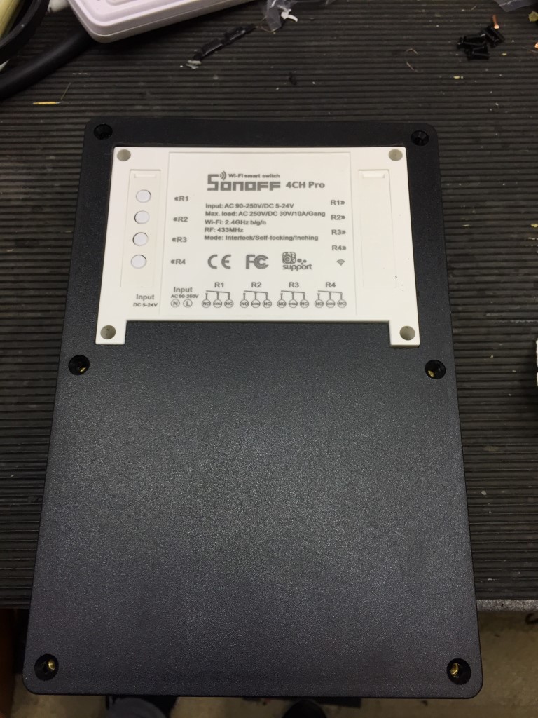
I decided to mount the Sonoff 4Ch Pro in a 220 x 150 x 96mm ABS enclosure (£9.70 eBay), in Visio I drew the cutting stencil and transferred this to the enclosure.
The width of the Sonoff needing trimming slightly to make a snug fit, the get the correct height I packed the unit with 25 x 25mm wood off-cut.
Using a Dremel equivalent, the lid was cut to accept the Sonoff.
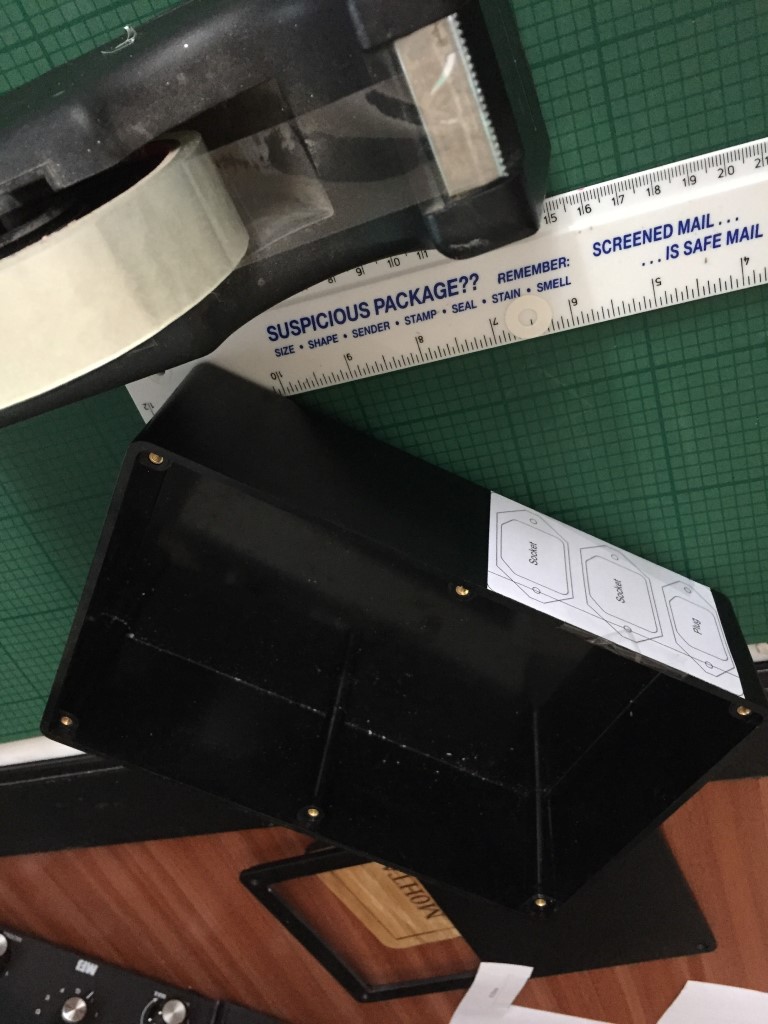
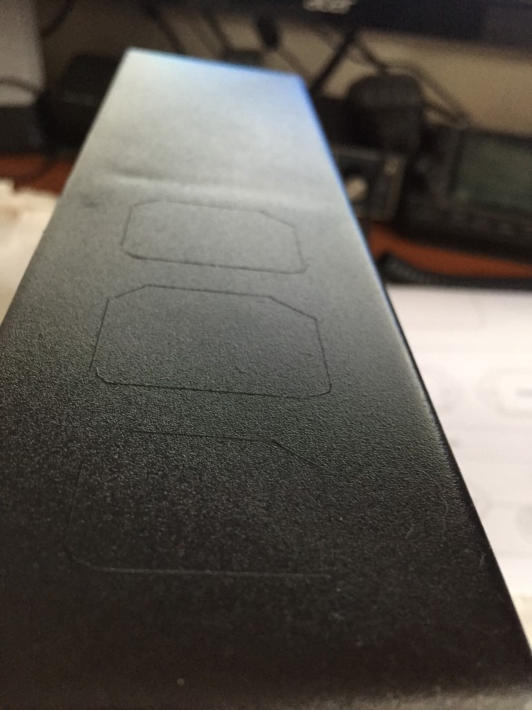
The IEC plug and socket stencil was attached to the side of the enclosure, using a scalpel, the cutting pattern was transferred.
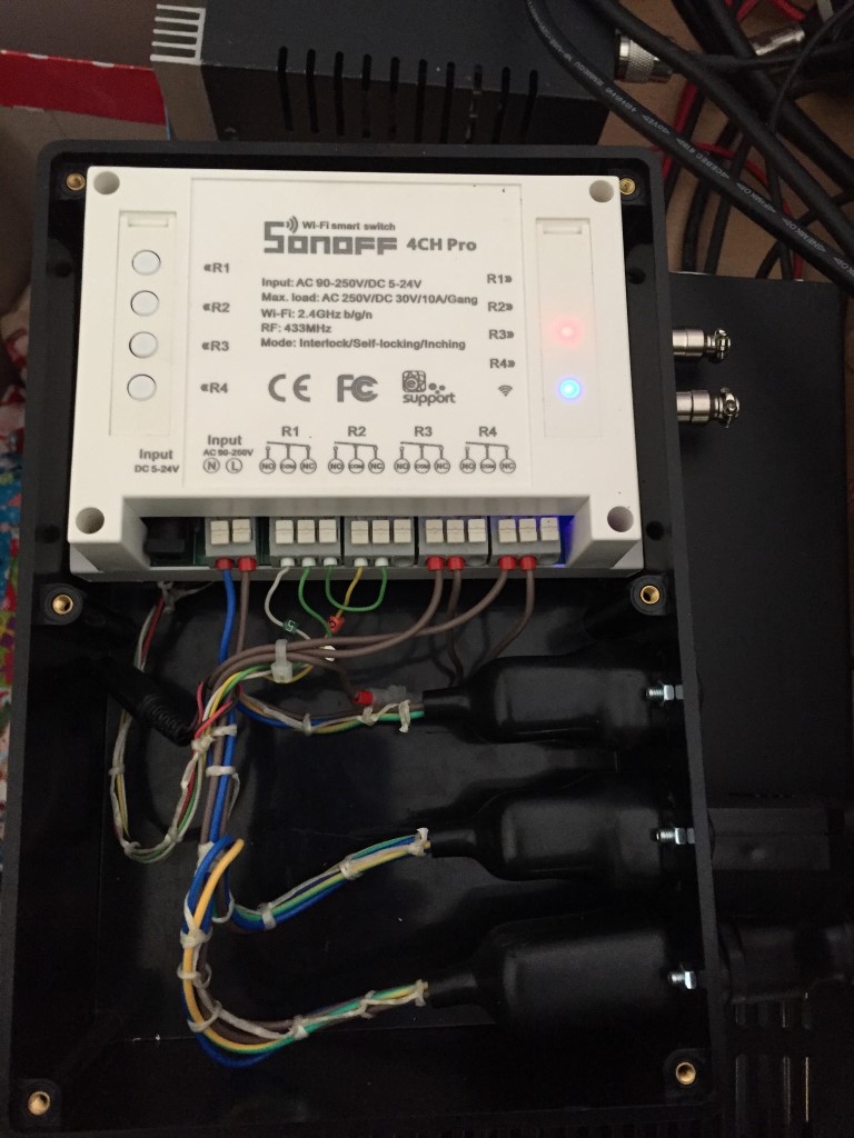
Wired Sonoff 4Ch Pro, Relays 1 & 2 momentarily switch +24v as a trigger input to either Raise or Lower my mast, Relays 3 & 4 latch to supply individual IEC outlets.
The Relays and outlets are rated at 10A, the feeding plugtop has the appropriate fuse fitted.
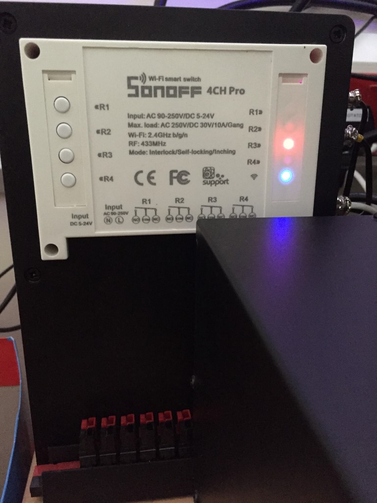
Finished unit tucked behind a PSU, LEDs show that Relay 3 is energized and WiFi is connected.
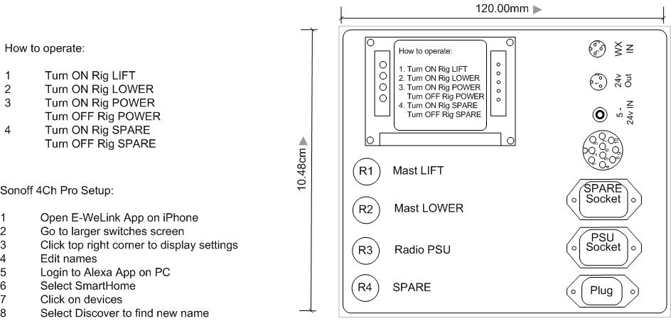
The label below is the remind instructions on the voice commands (prefixed with ‘Alexa’) and how to change the relay names.
Update –
Had a huge headache trying to get this unit to re-pair once I had done some modifications to my home network and access point, looking through the help forums a large number of others are having the same problem, the solution which worked for was to put the iPhone in ‘Airplane Mode’ and follow the process to pair an Android phone (Touch) and not AP which had worked previously. What didn’t help was an unannounced outage of the European Sonoff servers!
The second issue which came to light was relay 4 would randomly operate, the fix was very simple, press and hold the internal S5 button to erase any pre-enabled RF switches.
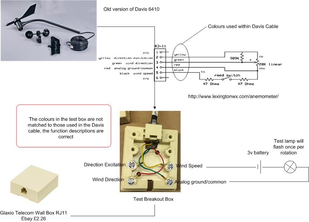
Link to WXForum excellent article on Anemometer and Vane – HERE
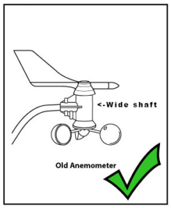
Davis 6410 Anemometer
25 October 17 my wind speed sensor failed after 9 years service, the symptom being that the wind speed is always at zero after checking the connection to the ISS is tight and the cable to the anemometer is not damaged.
This is the blog is how to replace the reed switch and test its operation, also while it was in bits, I thought I’d take the opportunity and replace the bearings as well.
Information Sources
Online sources of information relating to replacing the Davies 6410 reed switch –
Magnetic Reed Switch 10mm MKA-10110 100v 0.5A Russia £3.50 for 10 from eBay.
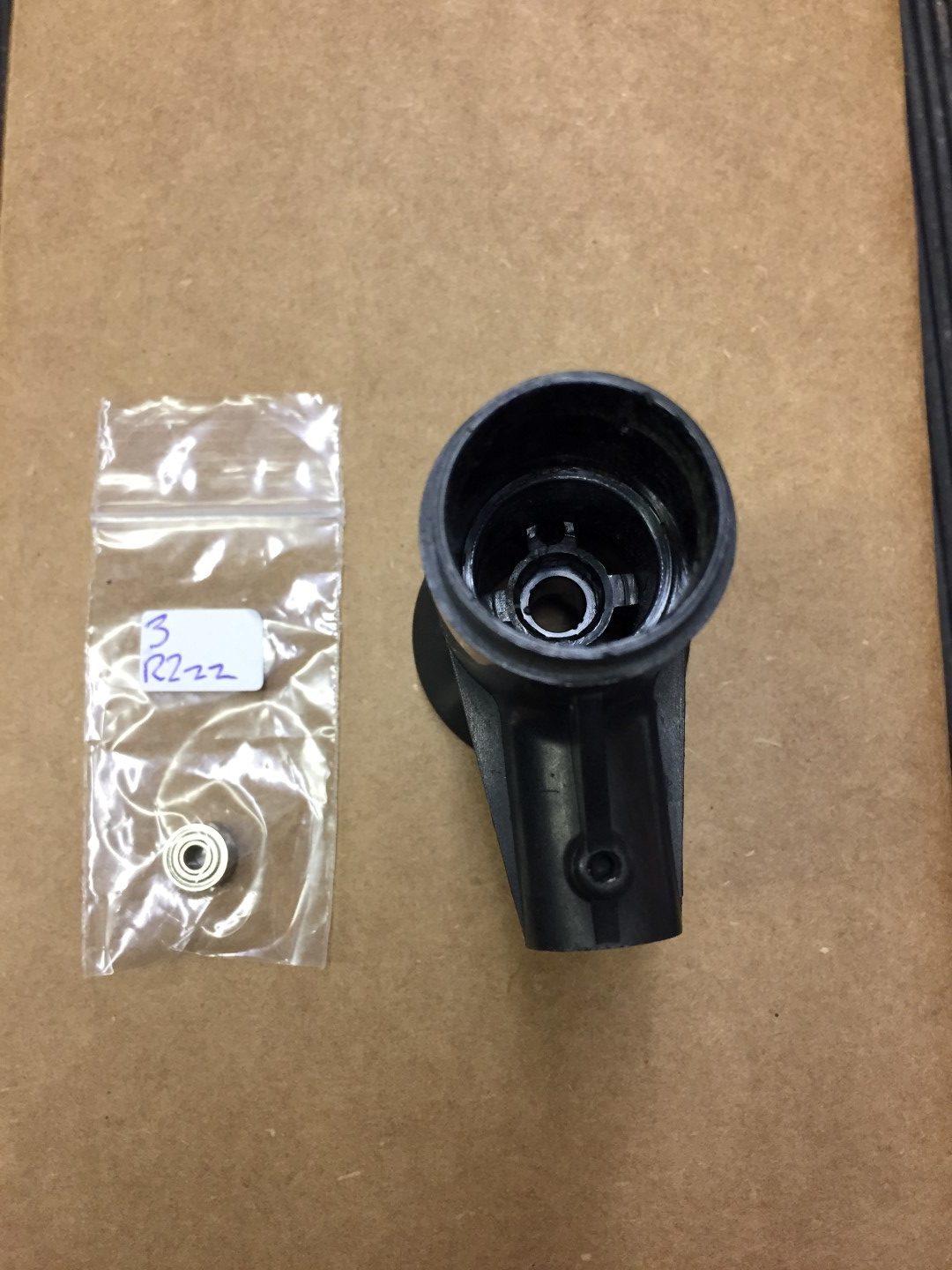
Metal Shielded Bearing 0.125 x 0.375 x 0.156 Part R2zz £0.85 each from rcbearings.co.uk
Tools Required
Pliers
Sharp knife
Marker pen
Phillips screwdriver
1.25mm or 0.05″ allen key
Soldering Iron & Solder
Magnifing Glass
Terminal Screwdriver
Glue gun (or similar adhesive)
Multimeter or battery & lamp.
Step 1
Remove the vane and wind speed cups to avoid damage.
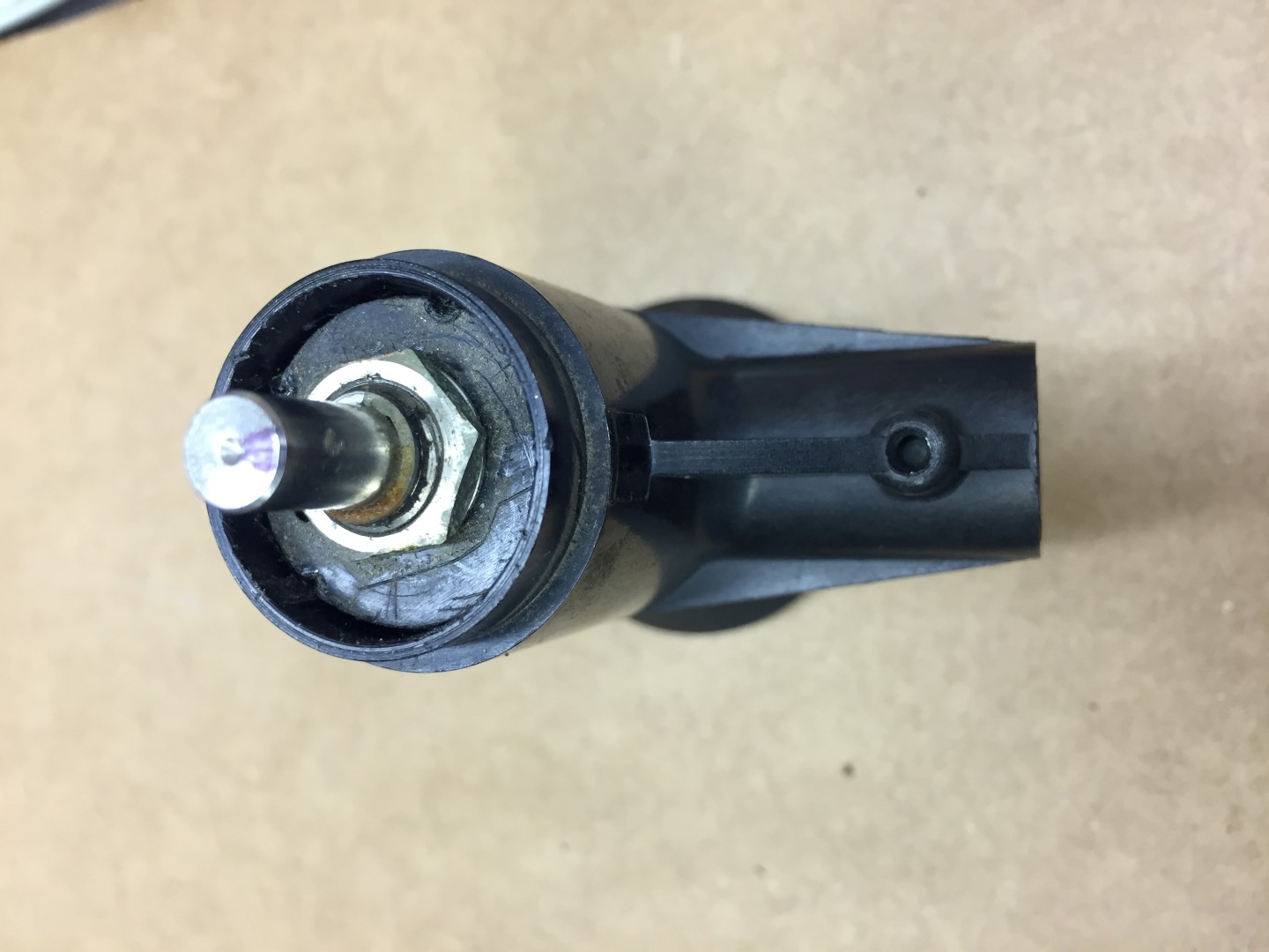
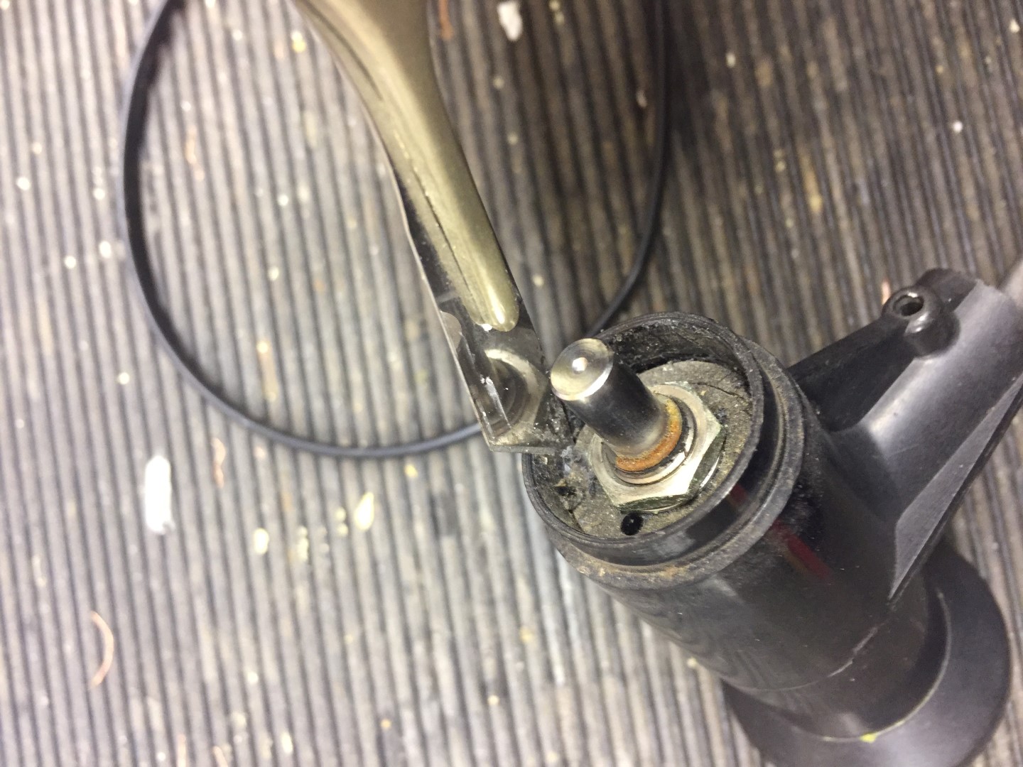
Undo allen screw, if tight, use penetrating oil first, the screw does not need to come out.
Once the allen screw is loose, the vane is an interference fit, and with a little gentle force, pulls up revealing the potentiometers (pot) shaft.
The shaft is not ‘keyed’ but will have a mark where the allen screw tightened against, when you reassemble, use this to align the vane so the screw tightens in the same place.
I marked the shaft showing the allen screw mark, I also marked the body of the pot in relation to the housing so that when I reassemble everything is in the same position and the wind direction reading will not be out.
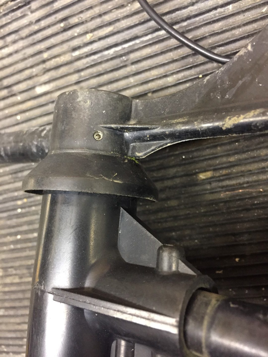
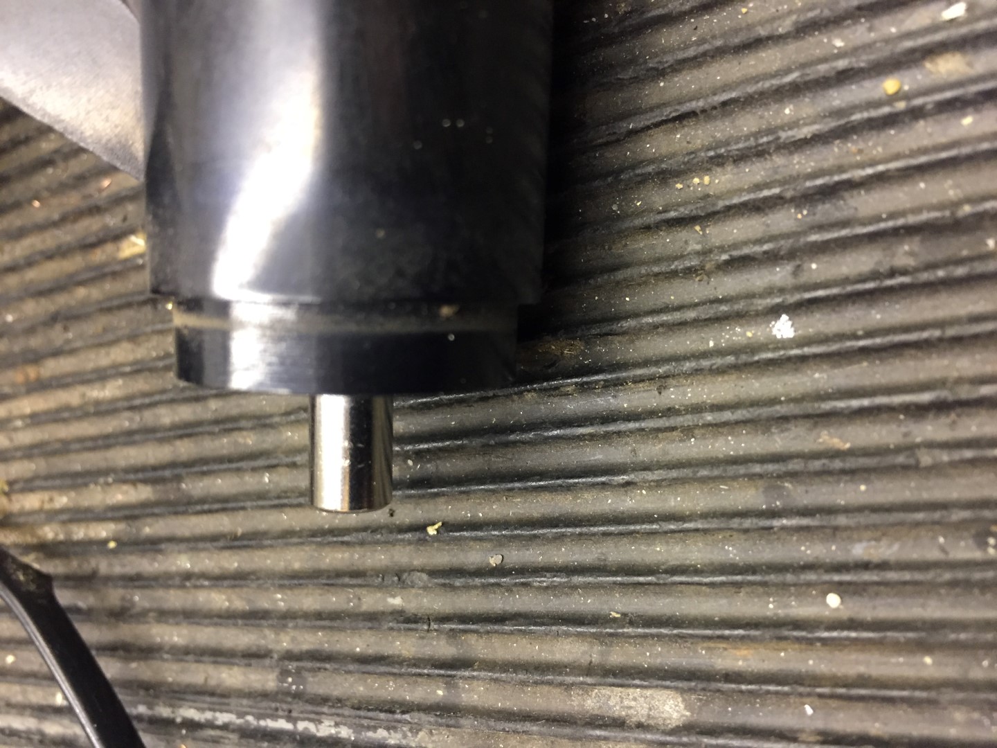
Step 2
Using the same allen key, undo the securing screw on the wind cups, once loose, the assembly slides off the shaft with little force.
Put the wind cups and vane in a safe place till later.
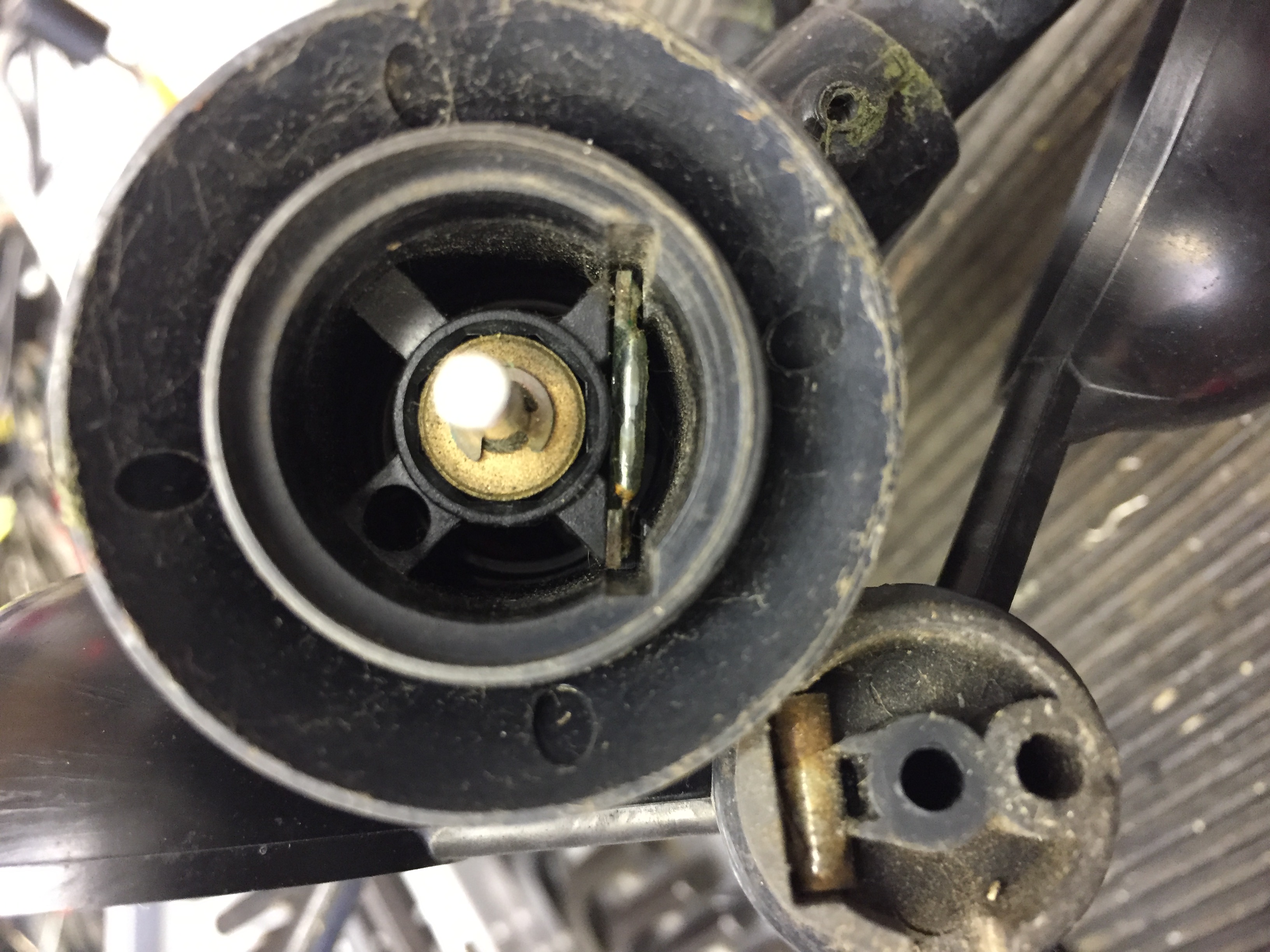
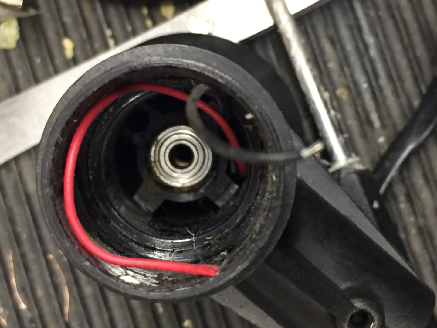
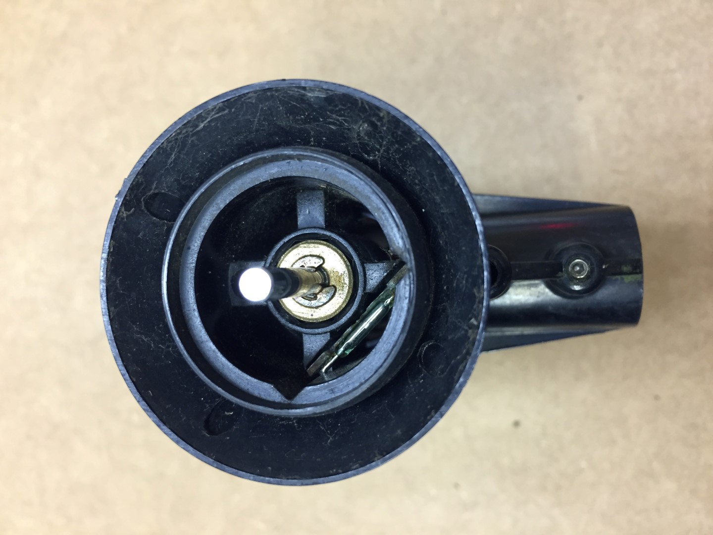
Removing the wind cups reveals the reed switch which can only be accessed by removing the pot.
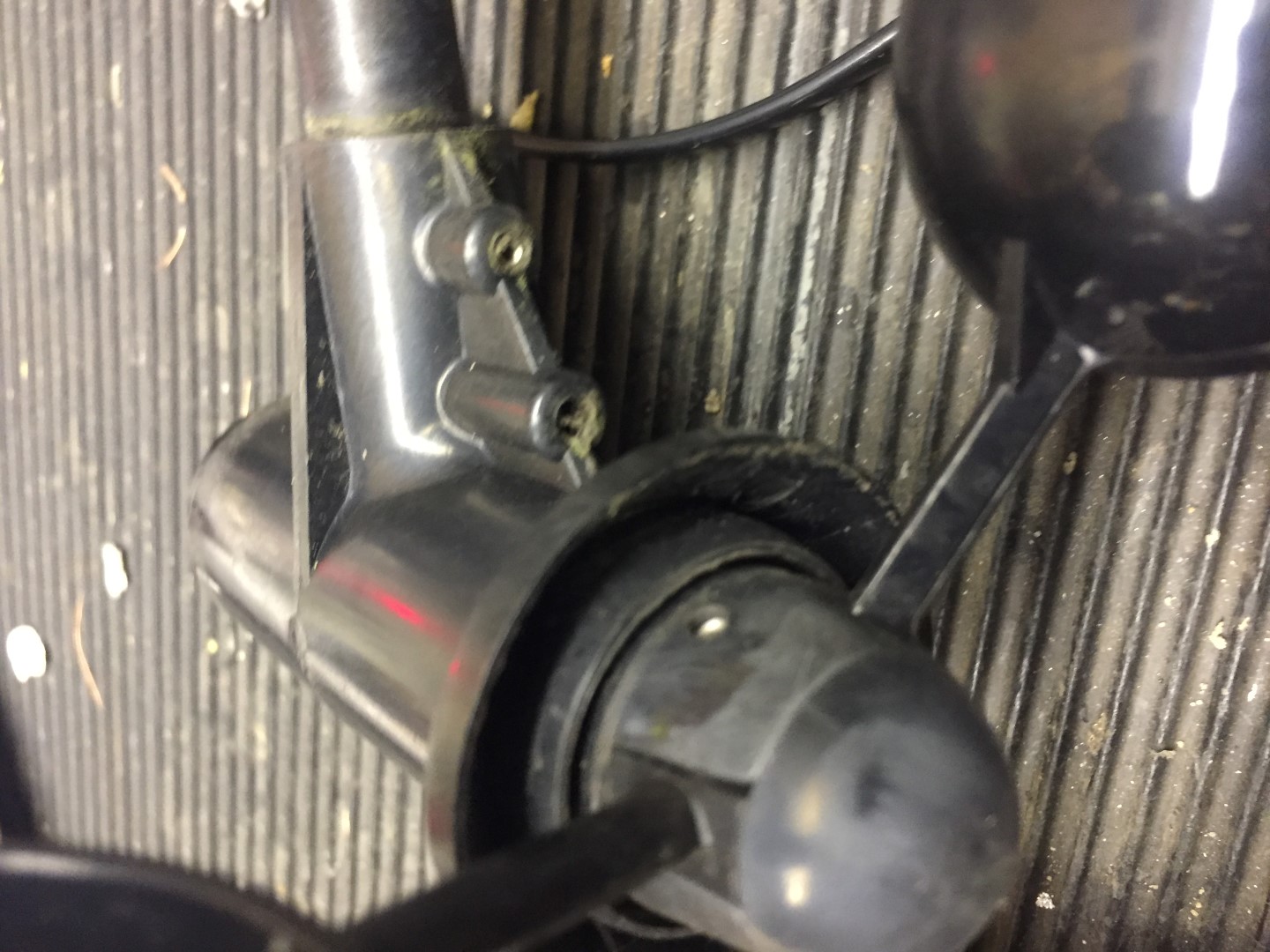
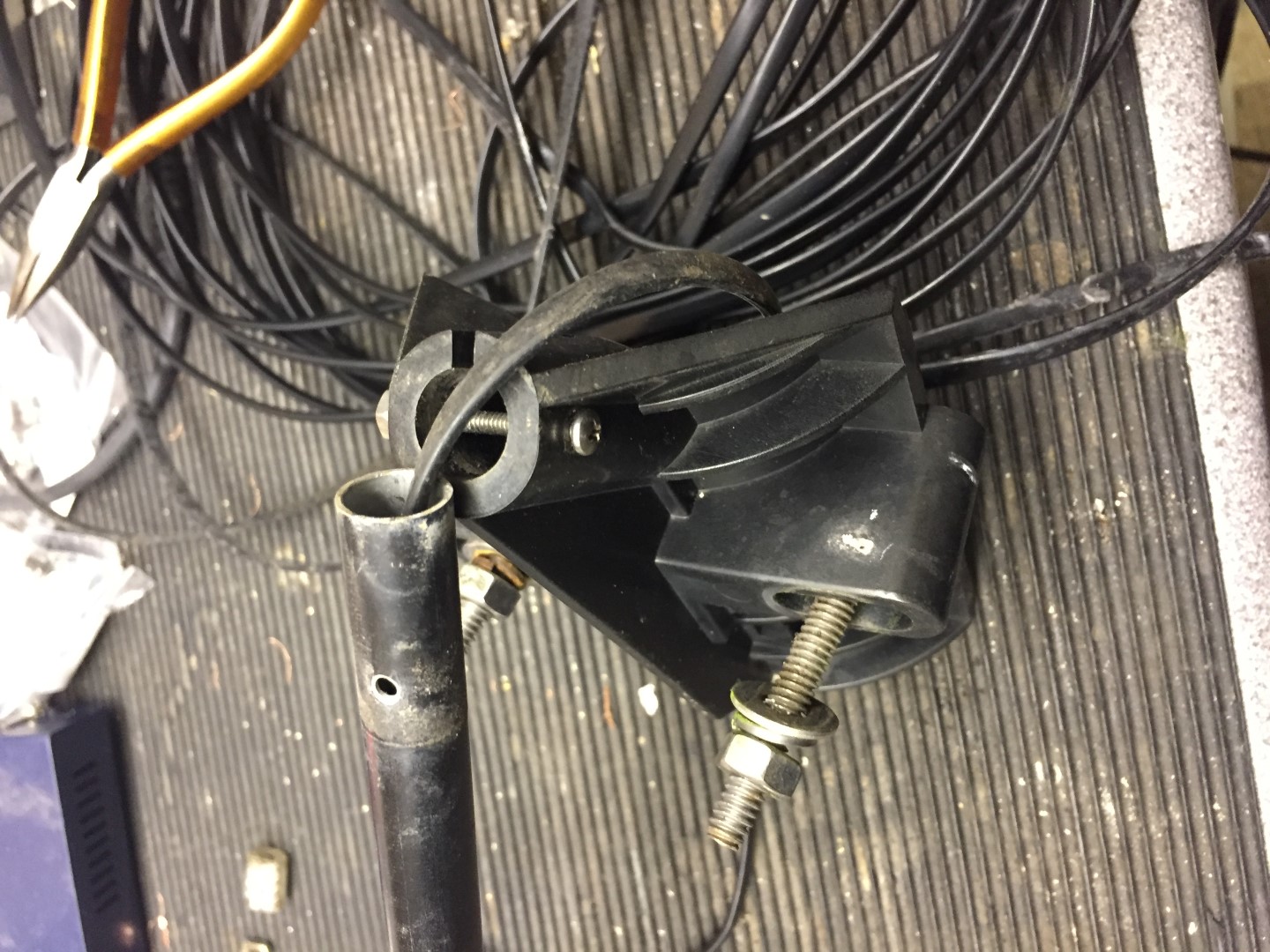
Step 3
Breaking down the arm and releasing the cable, this is important when we come to remove the pot.
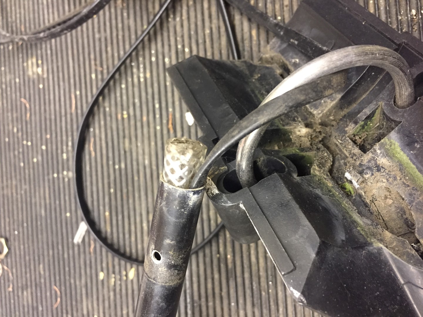
Undo the machine screw and slide this out, once the cable has been released from the in-built grips of the mounting bracket, the tube should slide out of the housing.
The cable inside the tube has a crude cable grip made from an off-cut of plastic hose, either use pliers or a wood screw in the center of the hose, and gently tease it out.
The next part is to slacken the two allen screws which hold the wind and direction body to the arm, once done, slide the arm down the cable to give you working room.
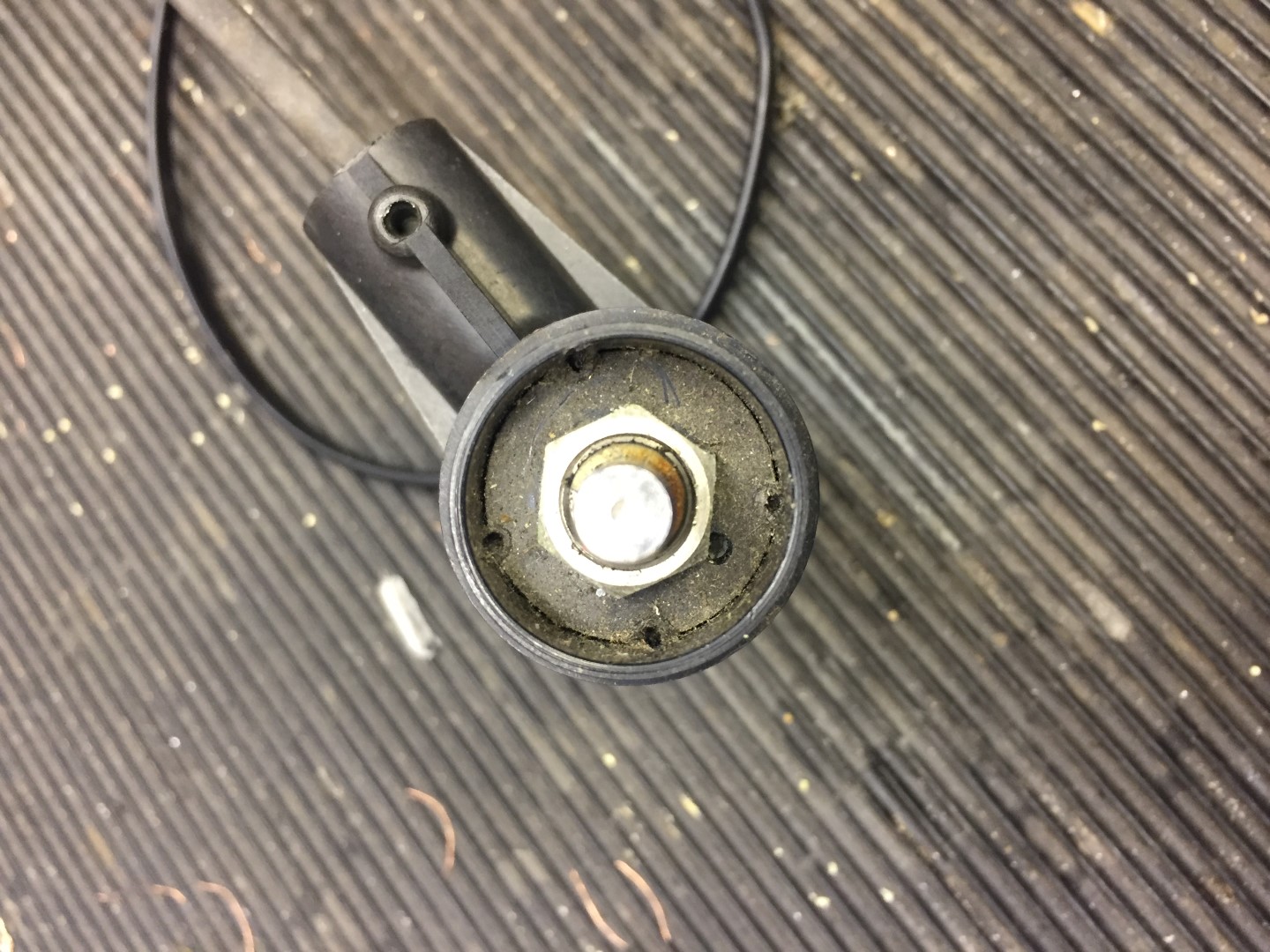
Step 4
Removing the pot, this is a push fit and held in place by hot melted indents, these need to be cut away with a sharp knife.
Once the indents have been cut away, the pot will pull out of the housing, NOTE – this is a tight fit, use pliers to hold onto the pot shaft and draw towards you, Warning – I pulled too hard and pulled wires off the pot as their is not much slack in the wires from the reed switch, it’s not the end of the earth if you do though as I cut them off anyway!
Note red wire snaped as I pulled to hard removing pot.
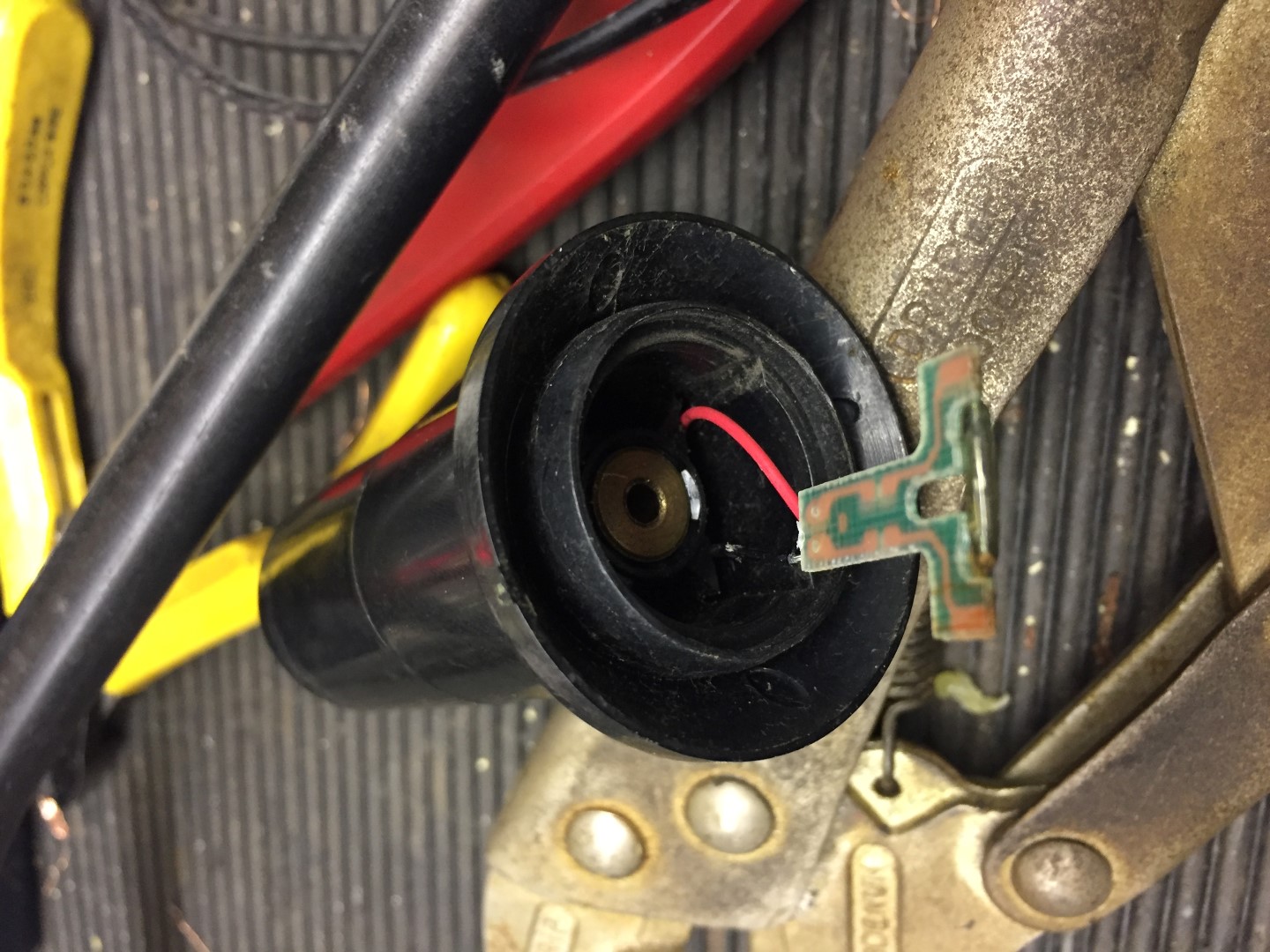
Step 5
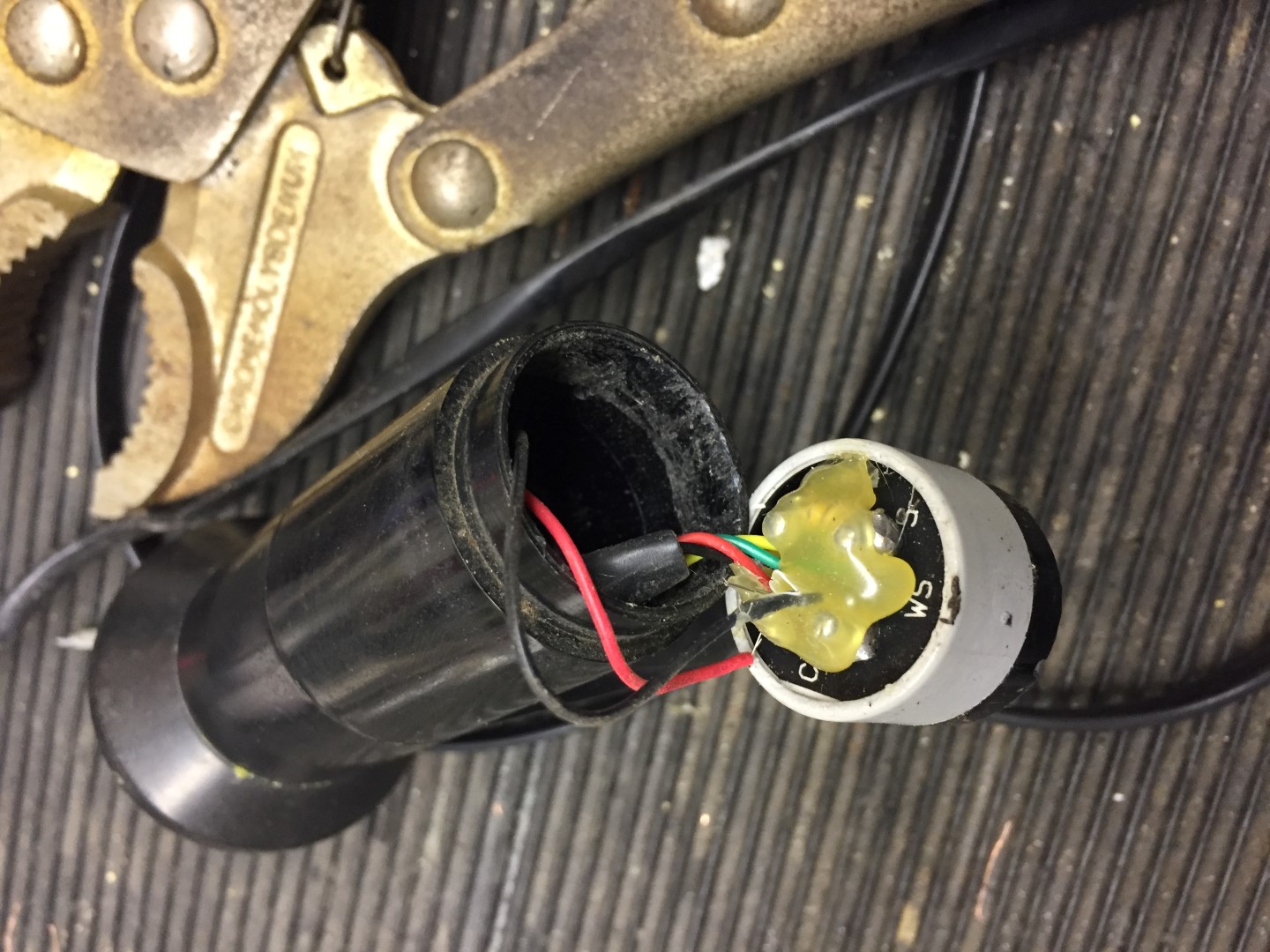
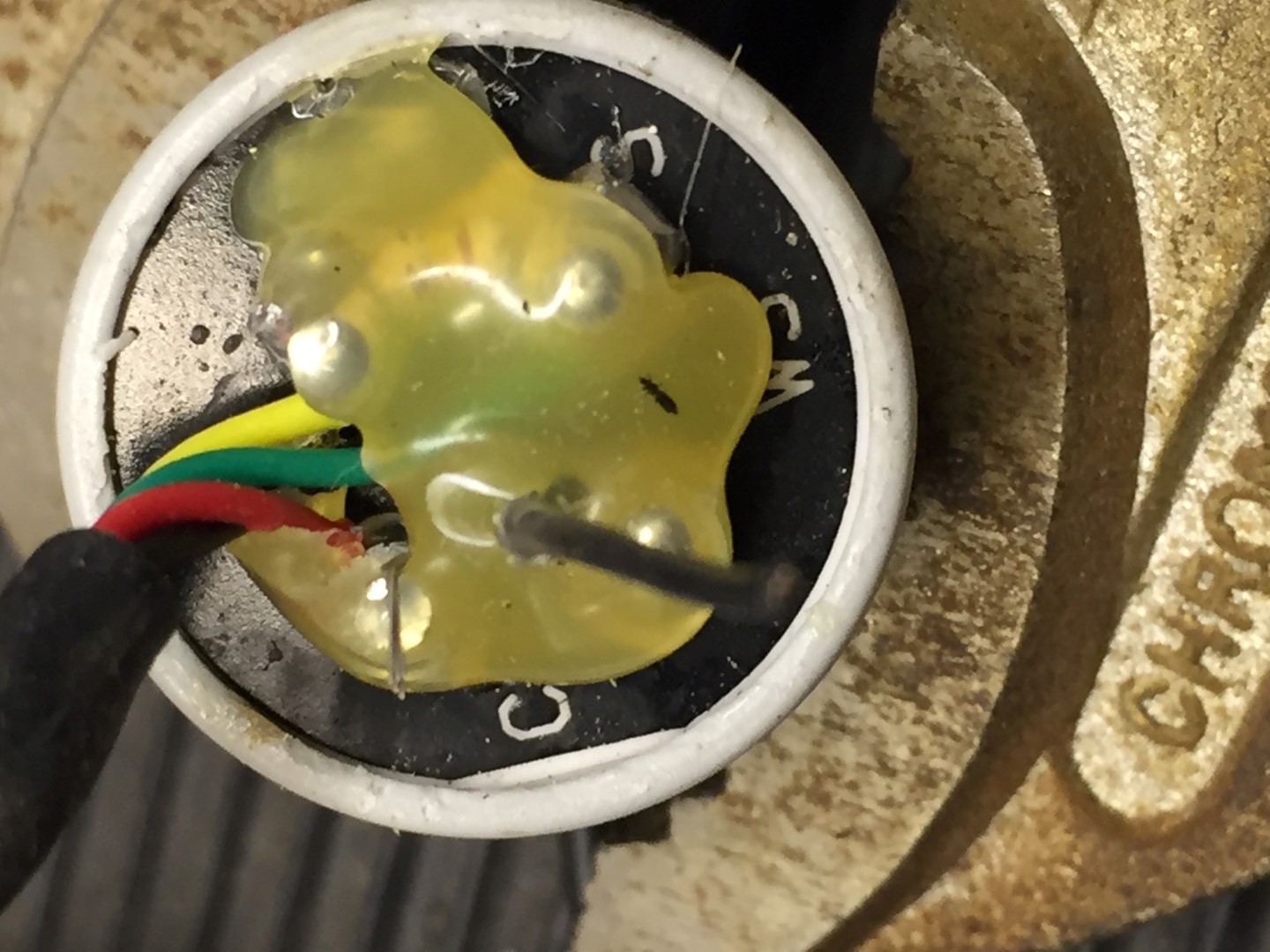
Remove the gunge from the rear of the pot and note which colour wires go where, the red and black fly lead go to the reed switch and these I cut, I also cut all wires to the pot and removed this so I could easily work on the reed switch and bearings.
Step 6
The reed switch is held in place with the same gunge (hot glue?) as is on the rear of the pot, due to aging it had gone brittle, using a terminal screwdriver it was possible to break this up from inside the housing body.
Once glue is removed, the reed switch assemble will slide out.
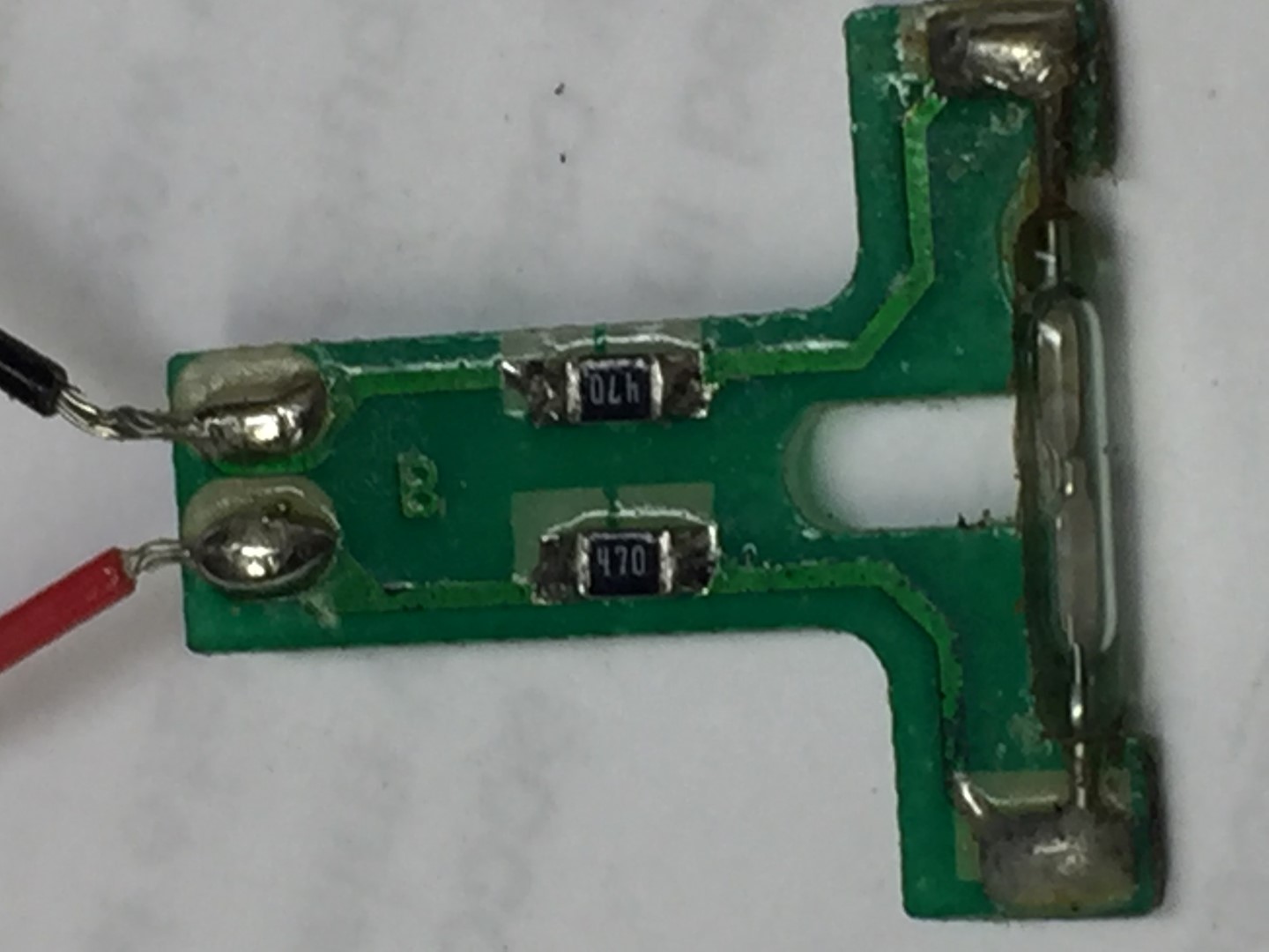
Step 7
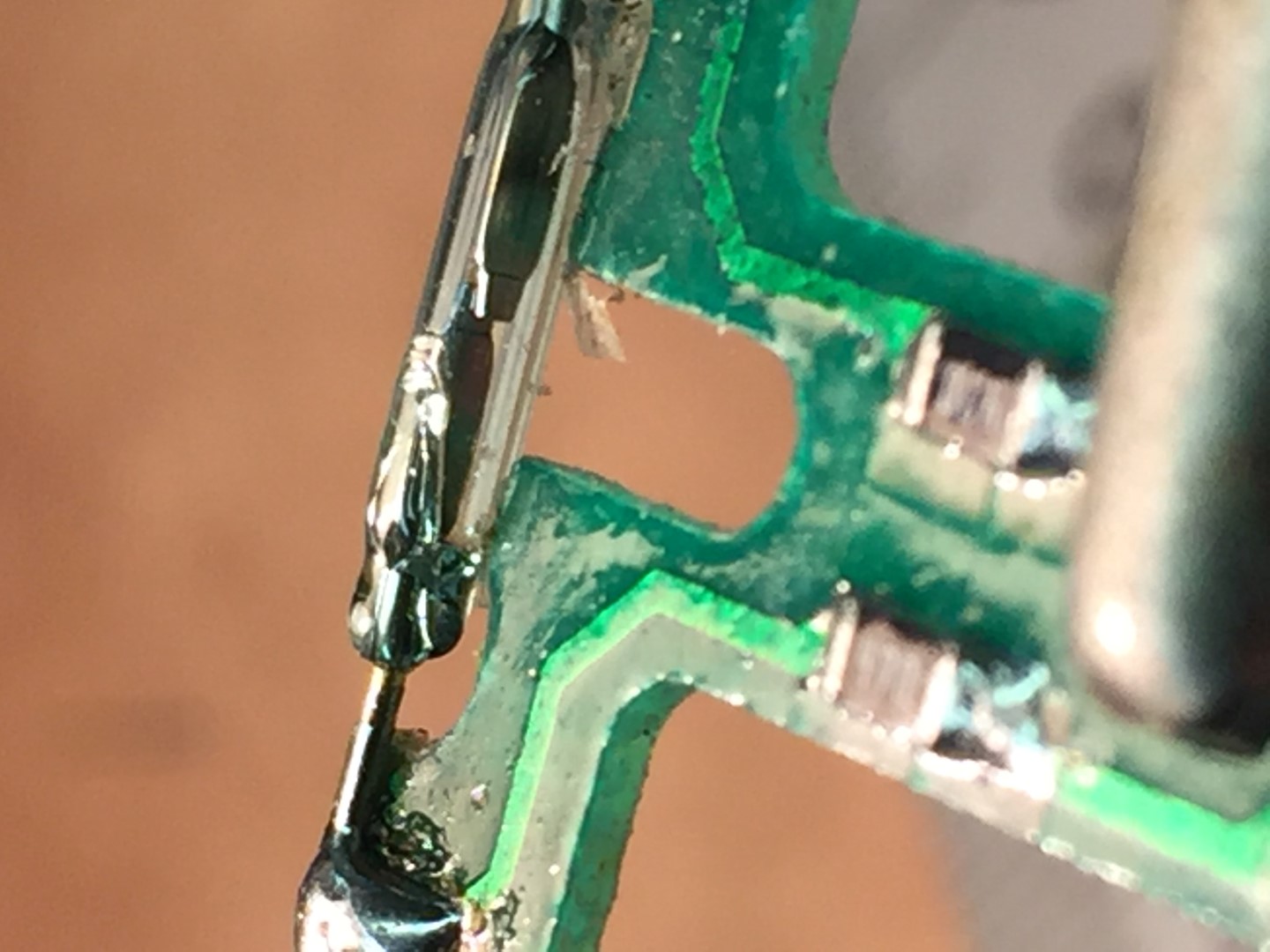
Reed switch replacement, the reed didn’t appear to be visually damaged, only slight rusting. Testing with a meter and magnet, the reed flexed but no electrical contact was made, checks on the circuit board tracks and resistors were OK.
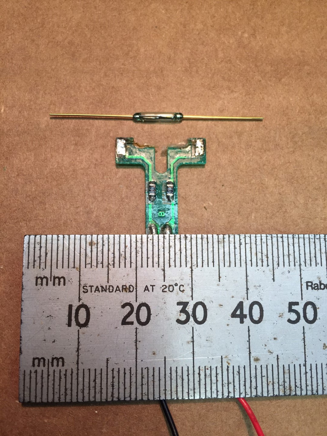
The zoomed pictures make things look easier to handle than they are, the picture below offers some scale.
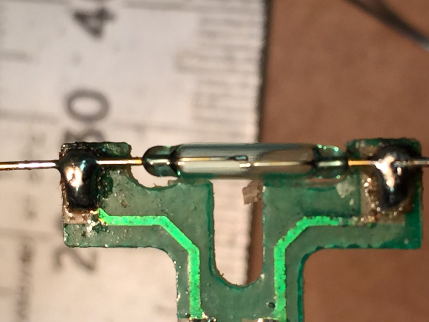
New reed soldered into position with the contact leafs horizontal to the orientation of the PCB, I also replaced the Red and Black wires from the PCB with more flexible ones.
Once the reed switch excess wire was trimmed, sliding the PCB into the housing body and getting it flush broke the reed.
The cause was the reed needs sit,as flat as possible,inline with the PCB, I had used too much solder and this lifted the reed wires slightly off the PCB.
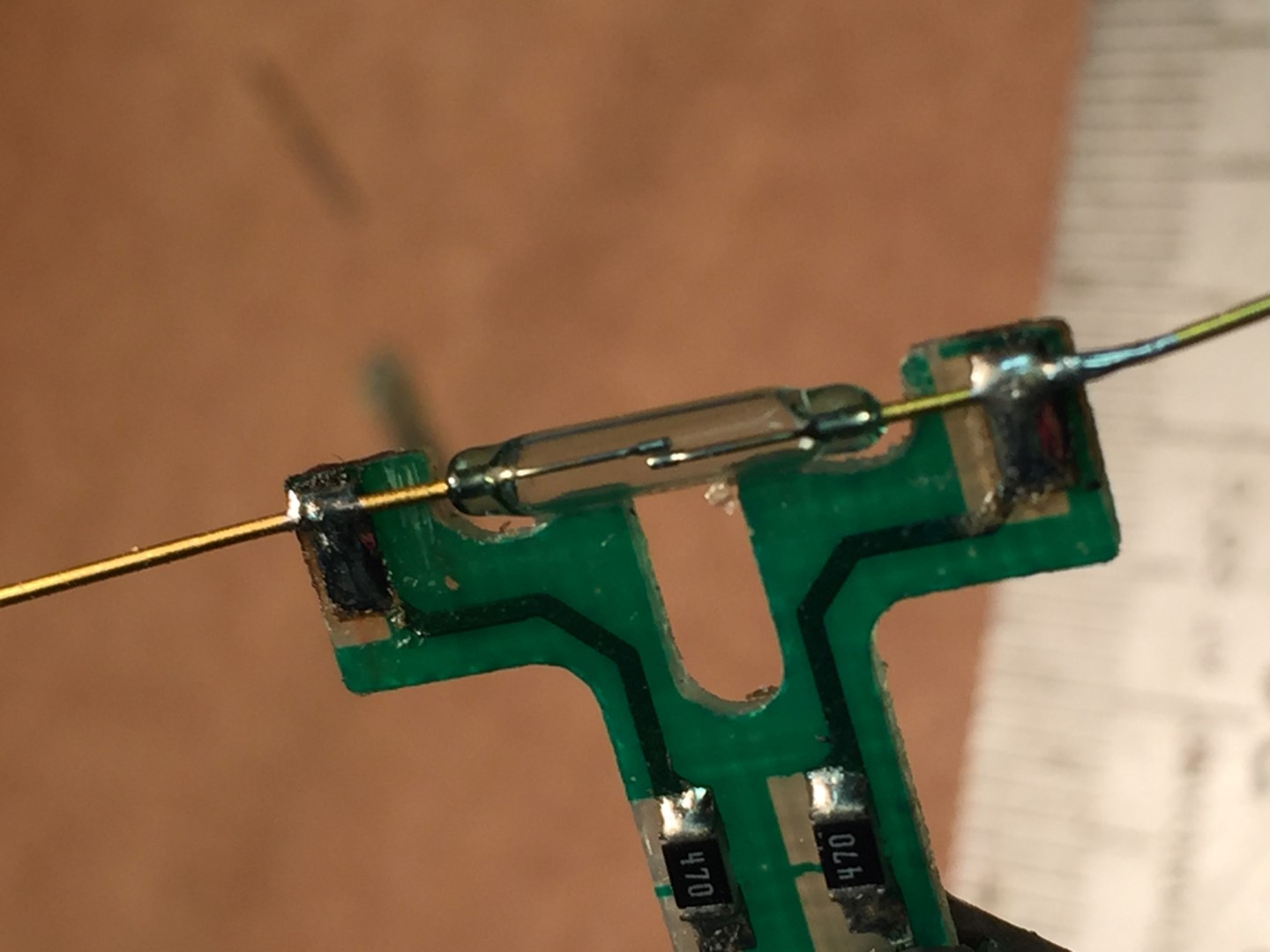
The picture below is the second attempt where I used minimal solder on the PCB pads and pressed the reed wires onto the pad before using a small amount of solder to connect to the pad. This seems to have worked and allows the PCB to slide into the housing and sit flush once the wires were trimmed.
After sliding the reed switch in the body, I connected a multi-meter on continuity buzzer setting, sliding on the wind cups and spinning them, this should cause the buzzer to sound once on each revolution.
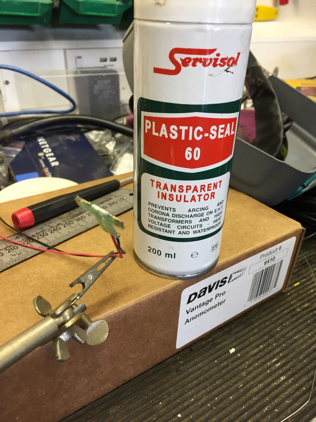
Once correct operation is proved, remove the wind cups and reed switch assembly, I sprayed the reed switch with a protective coating and put them in a safe place until later.
Step 7
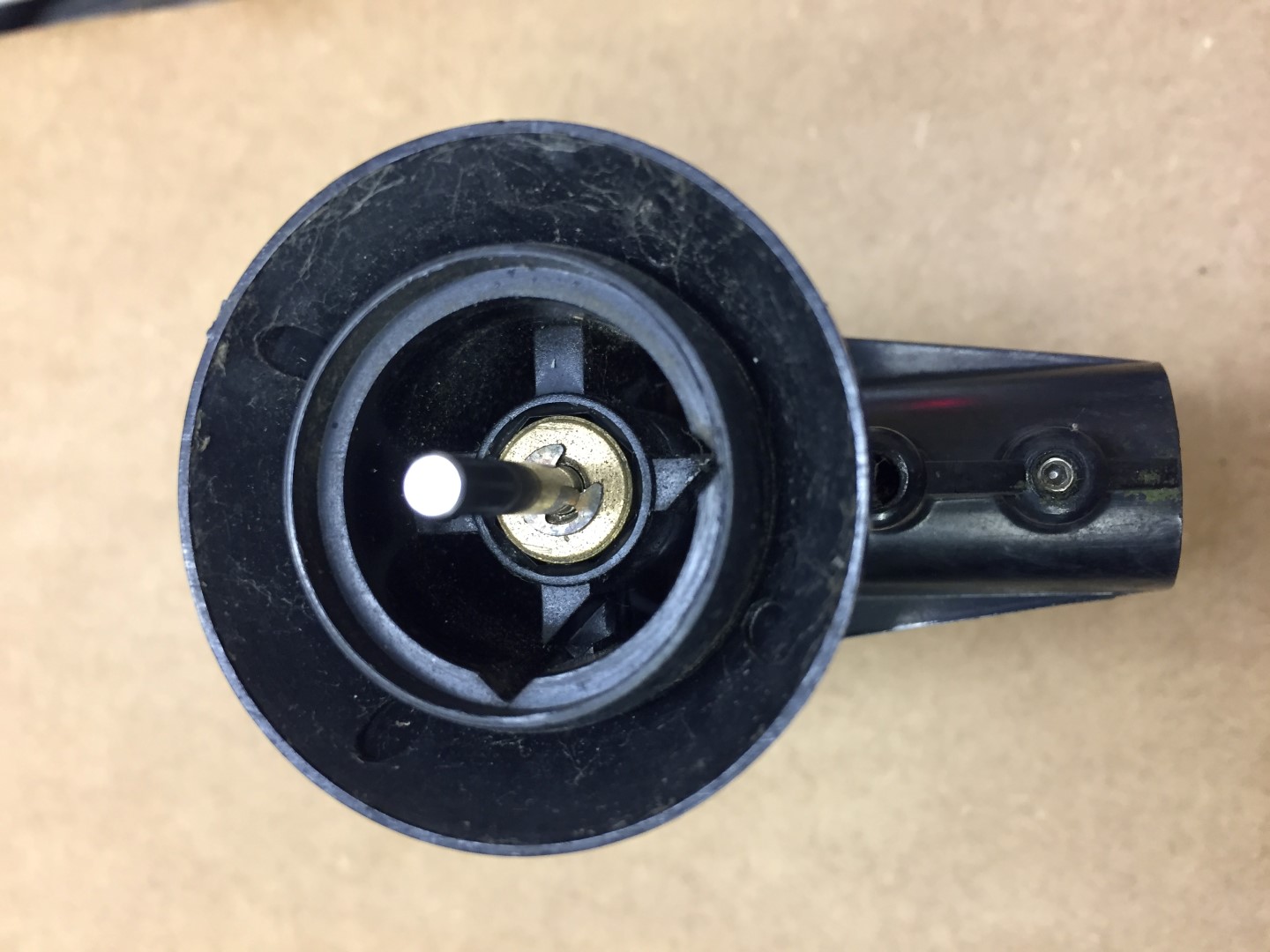
Replace the wind shaft bearing, first the circlip needs removing and retaining for later use, once the clip is off, the shaft can be pushed into the housing.
The shaft and black cap can now be removed.
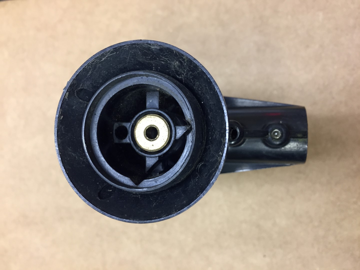
My model has the brass follower looking from the cup side, other pictures I’ve seen show this to be the bearing with the brass follower inside the body, I reassembled in the same order as I took apart.
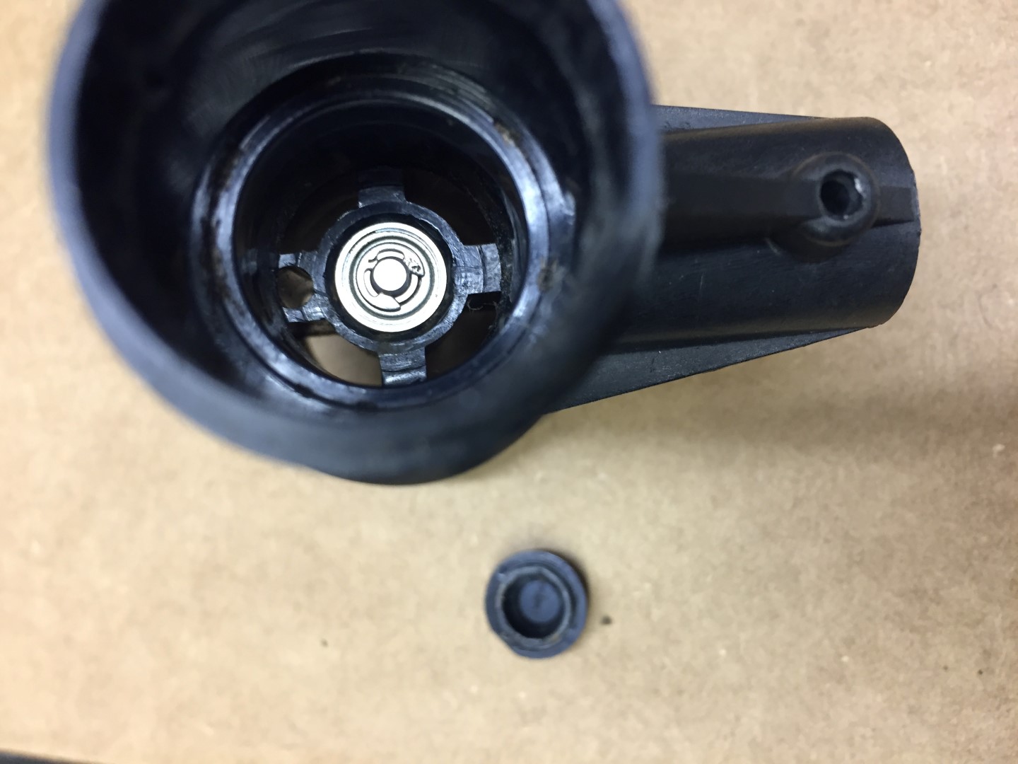
To remove the bearing, I left the brass follower in and used a terminal driver to go through the hole and using it at a slight angle, gently tap against the underside of the bearing, moving around the inside of the bearing and tapping to tease the bearing out of the housing.
The old bearing is in the bag and it is in good condition with only slight signs of rusting.
The new bearing simple pushed into the housing.
Step 8
Reassembly:
Slide shaft into place and fit circlip, make sure the shaft spins freely, I applied a light oil to the brass follower only.
Slide the reed switch into place and making sure that it sits flush, after putting the bearing protective cap on and I then used hot melt glue from inside the housing to secure everything in place.
Checking that the cable is still threaded through the arm, pass the cable into the housing ready for soldering onto the back of the pot.
Once with wires are back in place, I sprayed a protective coating on the pot and pushed it back into the housing checking that the marks I made at the start are aligned.
I didn’t melt fix the pot, the protective costing will act as an adhesive.
The arm was then re-affixed and secured.
The arm cable grip was pushed back in, check that the fixing hole is clear for the machine screw when pushing the grip back in.
Fix vane back on to pot, aligning grub screw with marking on shaft.
Fix wind cups onto shaft.
Testing
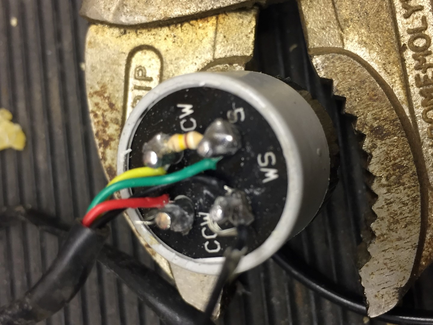
I used a Glaxio Telecom Wall Box RJ11 which cost £2.69 from eBay as a breakout box for testing that the reed and directing pot are working:
My old 6410 is now refurbished and will be stored in the loft until the one in use packs up.
If you need any further information, please contact me.
A blog about stuff that interests me or I have done.
We use cookies on our website to give you the most relevant experience by remembering your preferences and repeat visits. By clicking “Accept All”, you consent to the use of ALL the cookies. However, you may visit "Cookie Settings" to provide a controlled consent.
This website uses cookies to improve your experience while you navigate through the website. Out of these, the cookies that are categorized as necessary are stored on your browser as they are essential for the working of basic functionalities of the website. We also use third-party cookies that help us analyze and understand how you use this website. These cookies will be stored in your browser only with your consent. You also have the option to opt-out of these cookies. But opting out of some of these cookies may affect your browsing experience.
Necessary cookies are absolutely essential for the website to function properly. These cookies ensure basic functionalities and security features of the website, anonymously.
Cookie
Duration
Description
_GRECAPTCHA
5 months 27 days
This cookie is set by the Google recaptcha service to identify bots to protect the website against malicious spam attacks.
cookielawinfo-checkbox-advertisement
1 year
Set by the GDPR Cookie Consent plugin, this cookie is used to record the user consent for the cookies in the "Advertisement" category .
cookielawinfo-checkbox-analytics
11 months
This cookie is set by GDPR Cookie Consent plugin. The cookie is used to store the user consent for the cookies in the category "Analytics".
cookielawinfo-checkbox-functional
11 months
The cookie is set by GDPR cookie consent to record the user consent for the cookies in the category "Functional".
cookielawinfo-checkbox-necessary
11 months
This cookie is set by GDPR Cookie Consent plugin. The cookies is used to store the user consent for the cookies in the category "Necessary".
cookielawinfo-checkbox-others
11 months
This cookie is set by GDPR Cookie Consent plugin. The cookie is used to store the user consent for the cookies in the category "Other.
cookielawinfo-checkbox-performance
11 months
This cookie is set by GDPR Cookie Consent plugin. The cookie is used to store the user consent for the cookies in the category "Performance".
CookieLawInfoConsent
1 year
Records the default button state of the corresponding category & the status of CCPA. It works only in coordination with the primary cookie.
PHPSESSID
session
This cookie is native to PHP applications. The cookie is used to store and identify a users' unique session ID for the purpose of managing user session on the website. The cookie is a session cookies and is deleted when all the browser windows are closed.
viewed_cookie_policy
11 months
The cookie is set by the GDPR Cookie Consent plugin and is used to store whether or not user has consented to the use of cookies. It does not store any personal data.
Functional cookies help to perform certain functionalities like sharing the content of the website on social media platforms, collect feedbacks, and other third-party features.
Performance cookies are used to understand and analyze the key performance indexes of the website which helps in delivering a better user experience for the visitors.
Analytical cookies are used to understand how visitors interact with the website. These cookies help provide information on metrics the number of visitors, bounce rate, traffic source, etc.
Cookie
Duration
Description
_ga
2 years
The _ga cookie, installed by Google Analytics, calculates visitor, session and campaign data and also keeps track of site usage for the site's analytics report. The cookie stores information anonymously and assigns a randomly generated number to recognize unique visitors.
_ga_92TJCVGJP2
2 years
This cookie is installed by Google Analytics.
_gat_gtag_UA_48800884_1
1 minute
Set by Google to distinguish users.
_gid
1 day
Installed by Google Analytics, _gid cookie stores information on how visitors use a website, while also creating an analytics report of the website's performance. Some of the data that are collected include the number of visitors, their source, and the pages they visit anonymously.
CONSENT
2 years
YouTube sets this cookie via embedded youtube-videos and registers anonymous statistical data.
is_unique
5 years
StatCounter sets this cookie to determine whether a user is a first-time or a returning visitor and to estimate the accumulated unique visits per site.
is_visitor_unique
2 years
StatCounter sets this cookie to determine whether a user is a first-time or a returning visitor.
sc_is_visitor_unique
2 years
StatCounter sets this cookie to determine whether a user is a first-time or a returning visitor.
Advertisement cookies are used to provide visitors with relevant ads and marketing campaigns. These cookies track visitors across websites and collect information to provide customized ads.
Cookie
Duration
Description
NID
6 months
NID cookie, set by Google, is used for advertising purposes; to limit the number of times the user sees an ad, to mute unwanted ads, and to measure the effectiveness of ads.
VISITOR_INFO1_LIVE
past
A cookie set by YouTube to measure bandwidth that determines whether the user gets the new or old player interface.
YSC
session
YSC cookie is set by Youtube and is used to track the views of embedded videos on Youtube pages.
yt-remote-connected-devices
never
YouTube sets this cookie to store the video preferences of the user using embedded YouTube video.
yt-remote-device-id
never
YouTube sets this cookie to store the video preferences of the user using embedded YouTube video.
yt.innertube::nextId
never
This cookie, set by YouTube, registers a unique ID to store data on what videos from YouTube the user has seen.
yt.innertube::requests
never
This cookie, set by YouTube, registers a unique ID to store data on what videos from YouTube the user has seen.