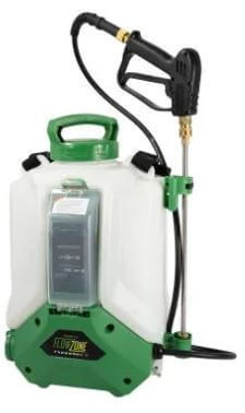
I bought a Flowzone Cyclone 2.5 battery pack sprayer and I love it, however I did experience a battery issue and the company were superb in sending out a replacement.
The issue I experienced was that the battery power level only indicated a red flashing LED after being on charge overnight, the battery test is operated by pressing the orange battery symbol and all green LEDs should illuminate after changing.
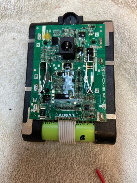
I did offer to send the faulty battery back to the supplier but they were happy for me to dispose of it, so I thought I’d open it up to see what’s inside.
A T10 x 50mm Torx security screwdriver was perfect to remove the four securing screws, the screws aren’t security ones, but it was the only one I had in the right size.
A cool feature of the battery is that the low voltage charging transformer lead plugs directly into the rear of the battery, no external charger is needed.
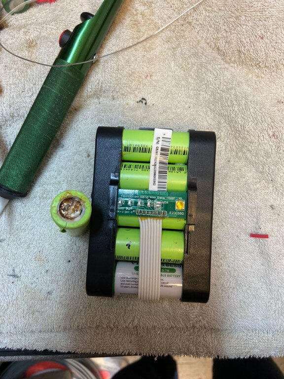
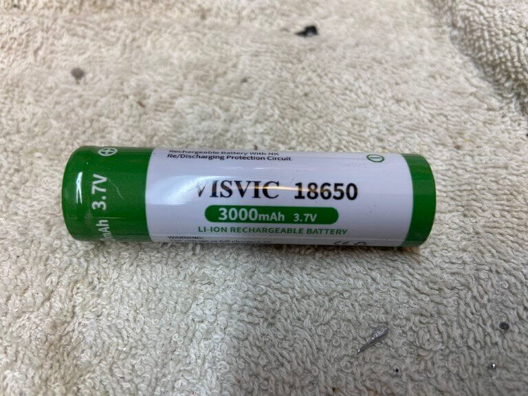
The battery pack contains 5 li-ion rechargeable 3.7v type 18650 batteries, once charged the voltage per battery is 4v, testing each battery in turn, it soon became obvious which one had failed as its voltage was 0.37v and the end cap showed signs of discolouration, not sure what caused this, maybe the battery compartment door wasn’t double clicked closed and water got in, I don’t know, but I’m very careful to make sure everything is dry by the battery just in case.
Above picture shows removed dead battery and the new one in-situ, battery cell replacement was quite difficult as the cell connections were spot welded on, and cells were interconnected, fortunately it was the end cell that needed changing so I peeled off the spot welded tab and unsoldered the tab connections on the PCB and this gave me enough room to get the old one out and the new one in.
Once the new battery was in I used some liquid flux, tinned the tabs and cell connections to make the heat contact on the battery as quick as possible using my Weller 100w soldering gun.
Everything works which is a result, also I have 5 battery’s left over as I had to buy 3 lots of 2, pity they don’t sell them individually they cost £20.62 but I do now have a spare, so can’t complain 🙂
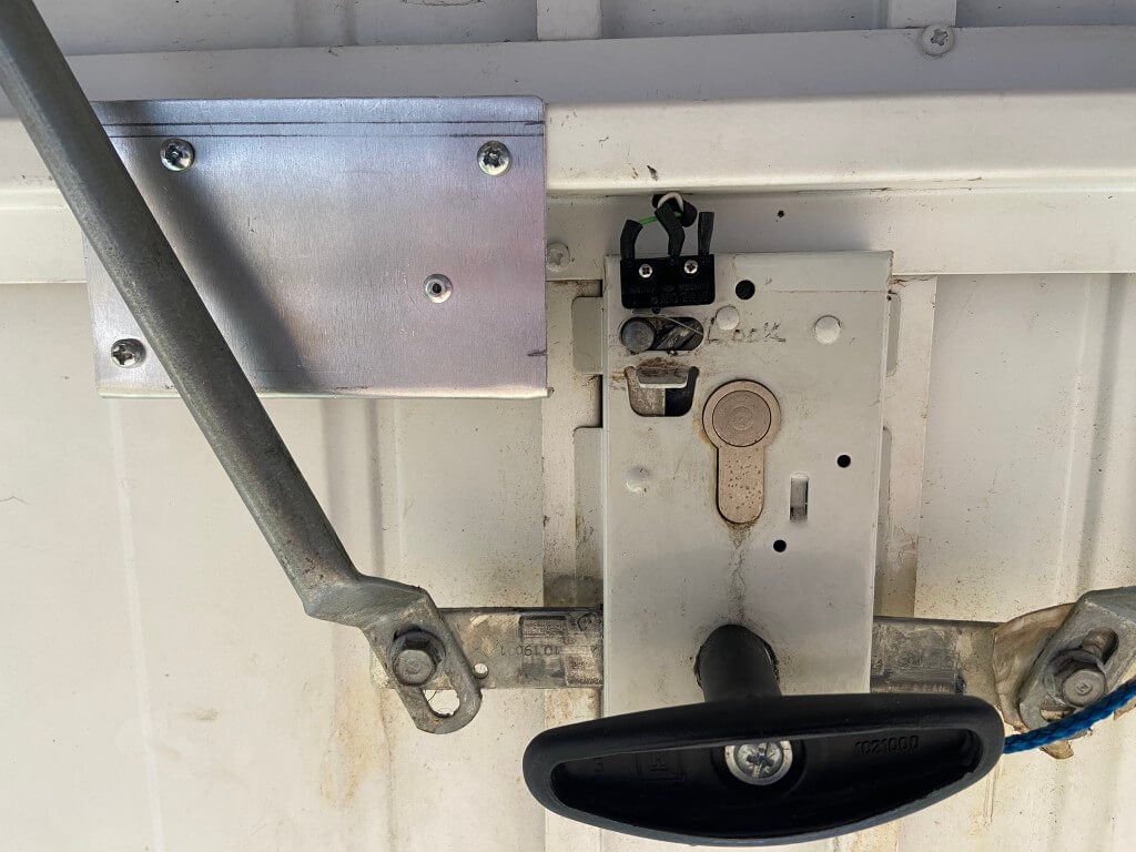
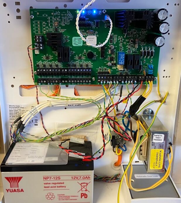
When I installed my Pyronix Euro46 house alarm, the garage was designed as a separate area allowing it to be set independently of other areas, to confirm final setting and to start the entry timer, a small lever microswitch was fitted to the sliding locking mechanism on the garage door.
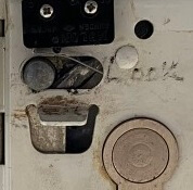
Microswitch to detect lock position
When the door is locked, the pin is over to the right; the picture above shows the door in the unlocked state.
This arrangement works really well, the biggest problem is when I come to set the alarm from within the house, only for the alarm to indicate that I had forgotten to lock the garage door, meaning I have to go outside to the front of the house and lock the door, a real niggle 🙂
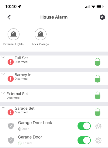
The image shows that the garage door is not locked, but now pressing the Lock Garage Icon will do this for me.
Locking Process
This is in two parts, the first being how the mechanically lock the garage door and the other is how electrically this would work with the alarm system.
The garage door can be locked with a key from the outside or by sliding the internal locking pin to the right, sliding the pin takes quite a force to manually move, so I took a punt and bought a 12v Micro Linear Actuator from Amazon, this has a 30mm stroke and can apply a force of 60N (6kg) and turned out to be ideal.
I mounted the actuator on a small sheet of 1.5mm aluminum and with the actuator fully extended, aligned the end of the arm to the full throw of the locking pin and tested operation with a battery, once happy, I used self tapping screws and affixed the aluminum to the garage door cross member.
The wires from the actuator and microswitch are taken off the door by a flexible door loop.
The triggering of the actuator was the next part to look at.
The actuator has an inbuilt limit switch, stopping the motor at each end of the arms travel, to operate, apply 12vDC and this will extend the actuators arm, reversing the 12v polarity will causes the actuator arm to retract and stop.
I could have physically connected the actuator arm to the locking pin enabling me to both lock and unlock the door electrically, the only problem with this is that the external euro lock would no longer work, as the locking pin would be held in position by the actuator arm which cannot be manually retracted.
Actuator Logic
The garage door to automatically lock when setting the alarm,
Ability manually trigger the locking actuator from the ProControl+ App on my phone,
If the door is locked the actuator has no need to operate.
Programming Euro46
The Pyronix Euro46 has a comprehensive number of programmable outputs and options which made the actuator logic easy to setup via the ‘InSite’ software.
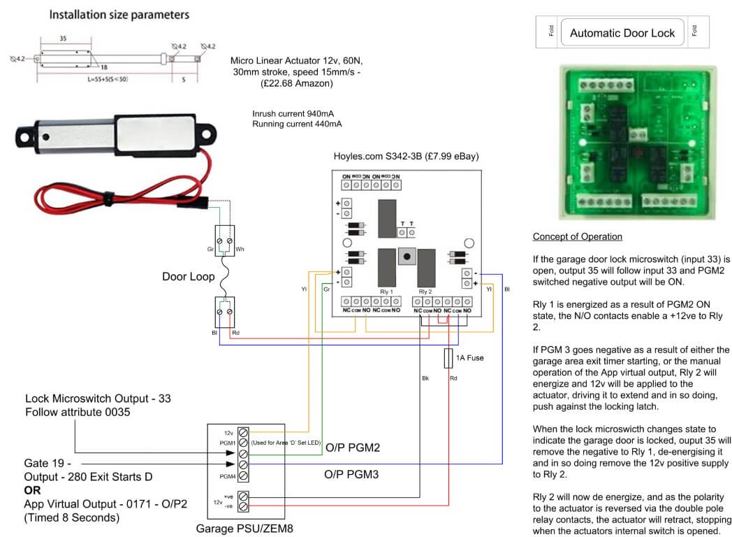
The garage has a PSU/ZEM8 which has 4 programable outputs, I used two of these Outputs for this project, Outputs 2 & 3.
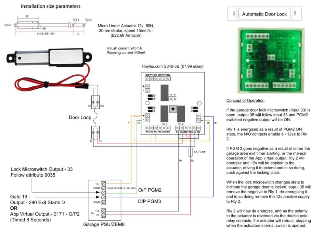
Output 2 was programmed to ‘Follow’ (Output type 35) the switch state of the lock microswitch (Input 33), if the lock is closed, the Output would go LOW enabling Relay 1 to energize, the contacts of this relay apply or remove a 12v positive to the trigger of Relay 2.
Output 3 was programmed as ‘Gate’, the gate is comprised of a combined OR logic within the panels software.
Output 3 would go LOW enabling Relay 2 to energize if the positive from Relay 1 was available.
Output 3 LOW conditions-
if the Exit time starts for Area ‘D’ (Output type 280),
OR
the Apps virtual Output is triggered (Output 0171 timed for 8 seconds).
Relay 2 simply changes the polarity of the 12vDC to the actuator, in the relays OFF state, 12v is applied to retract the arm, in the ON state the arm extends, once Relay 1 operates, Relay 2 will drop out causing the arm to retract.
All connected up with the door lock relays housed within the PSU/ZEM8 enclosure, 12v supply to the actuator is fed from the PSU and further fused down to 1A.
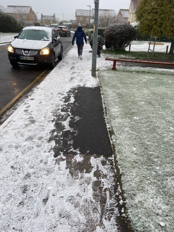
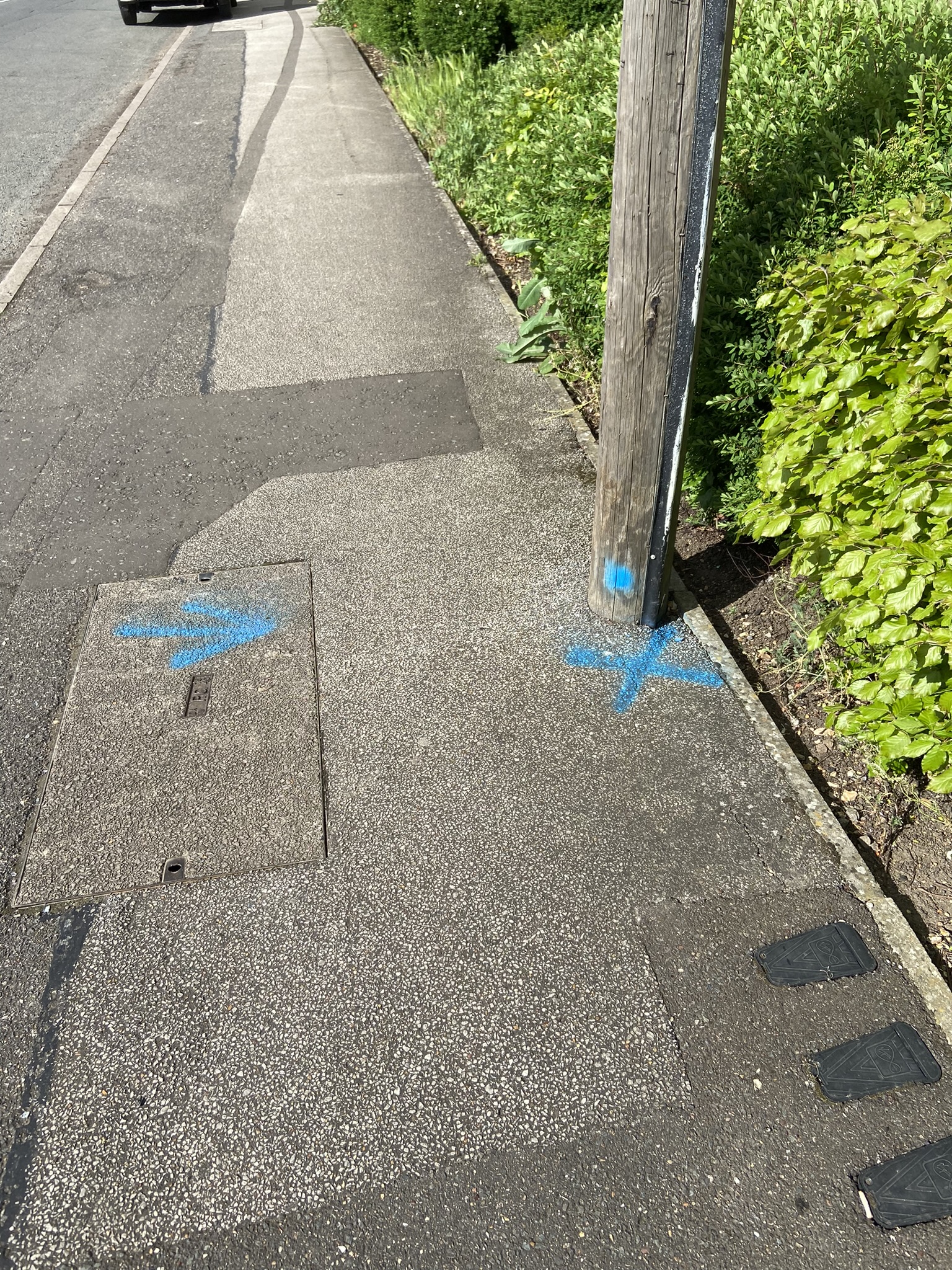
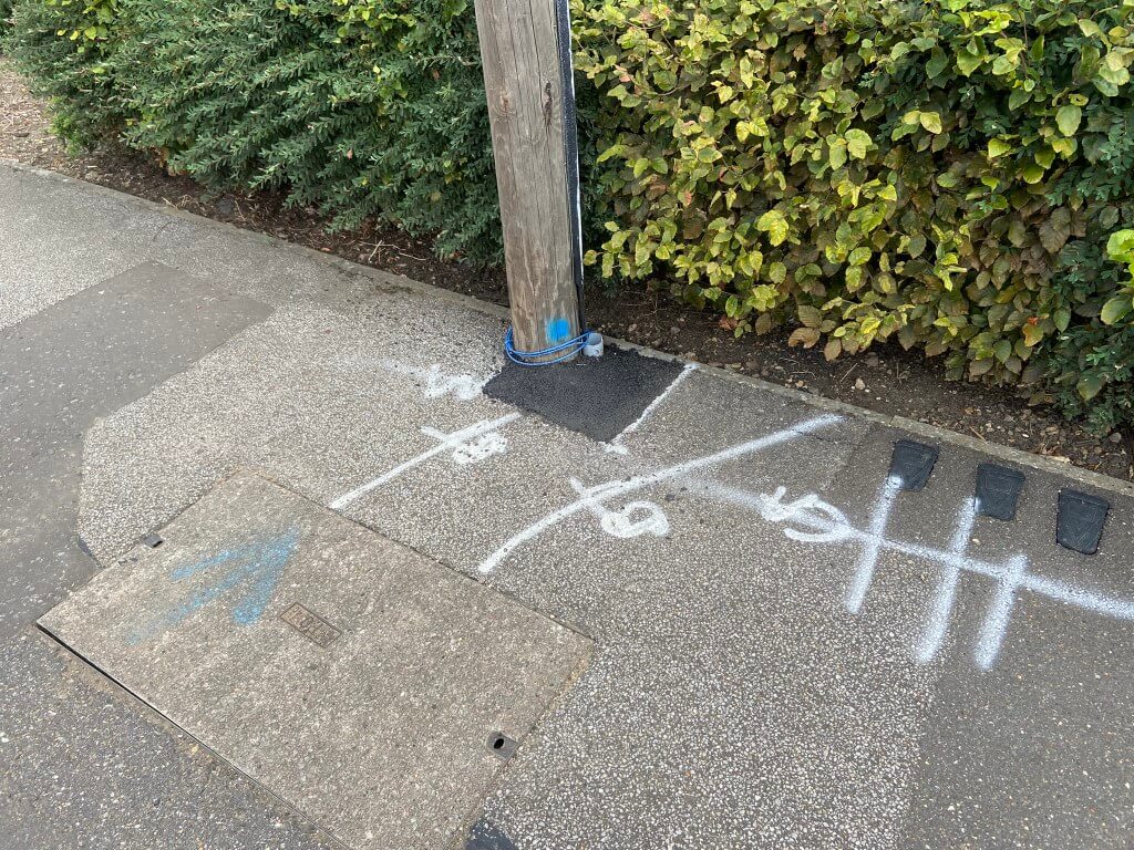
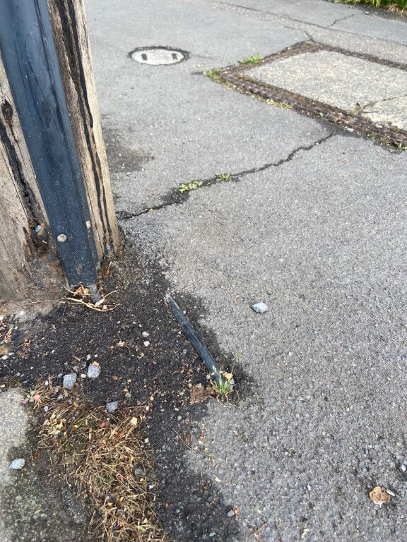
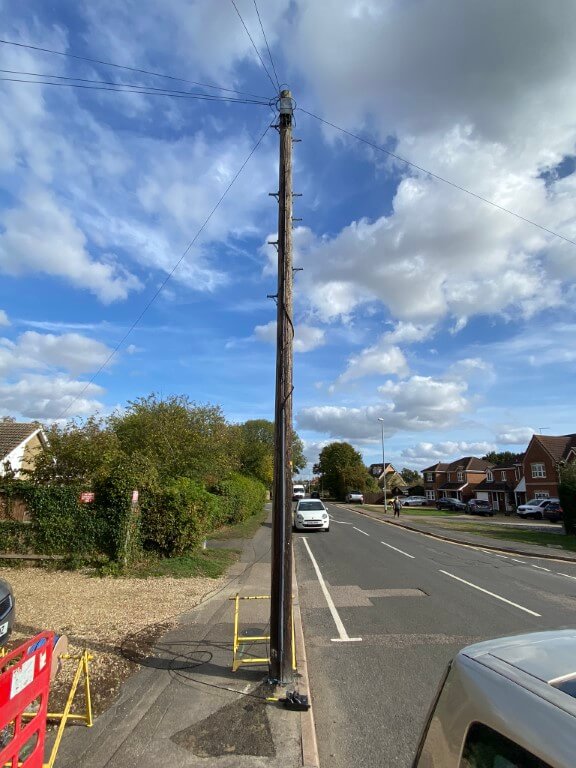
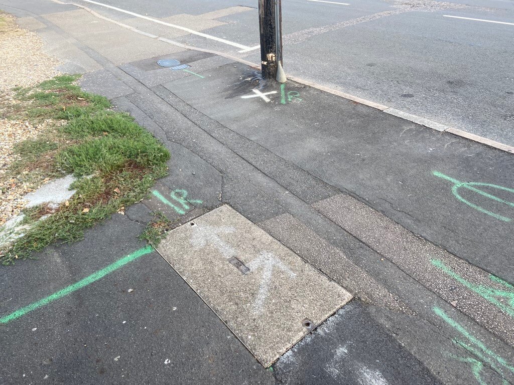
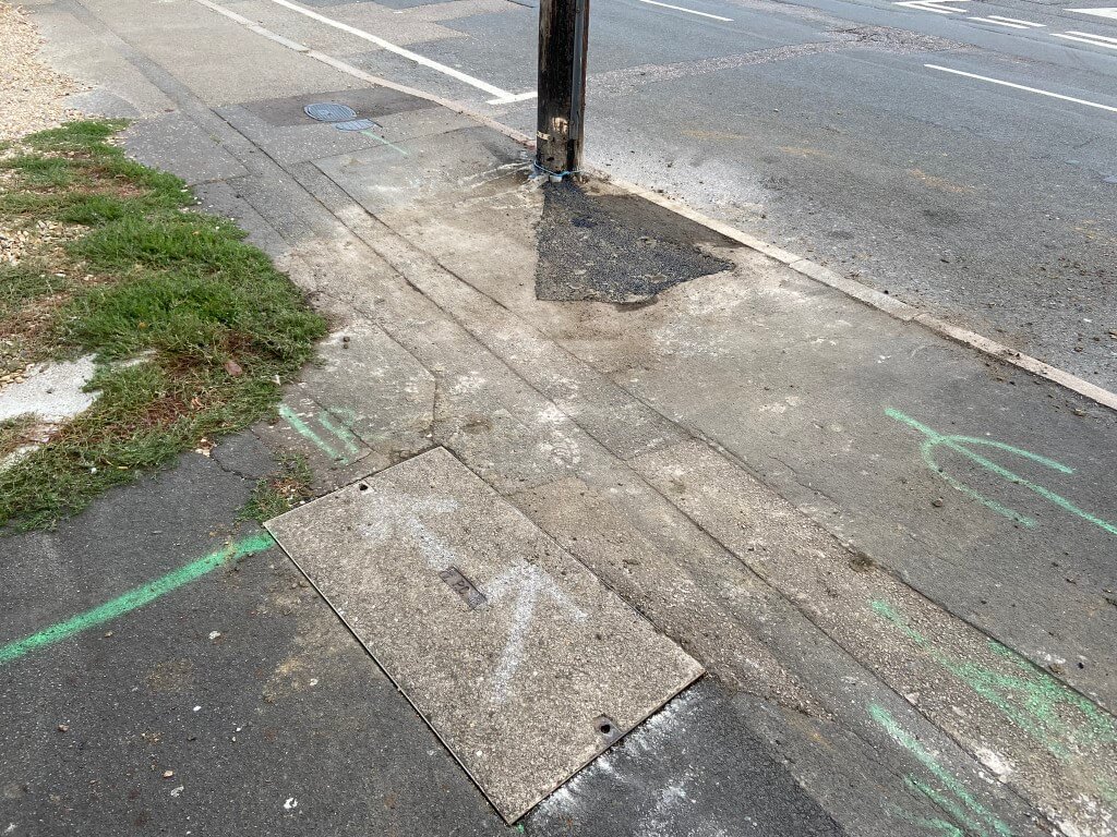
Overnight we had the first light dusting of snow and as normal we took the dog for his morning walk, when we got outside my house I noticed something odd had happened to the pavement.
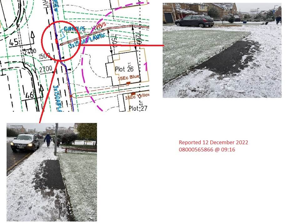
Now it didn’t take a genius to work out that something is getting warm under the pavement and melting the snow, and it looks like, at some point in time, that the area had been dug up before for some reason.
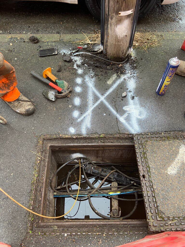
Having way too much time on my hands, I looked at electrical cable plans for my estate, and their it was, a significant cable joint:
Checking online, the network maintainer is UK Power Networks, telephone 0800 056 5866.
I gave them a quick call to let them know of the issue, the representative said they would send someone out to check it.
Why is it important to report this?
The simple answer is if the cable joint fails, it could be a catastrophic failure with the potential to cause harm or damage, or on a more basic level, result in a power outage until the joint is excavated and repaired.
Both can be avoided by early intervention, as an aside, I’ve noticed quite a few cable joints failing and my presumption is that this is due to the increase in Electric Vehicle charging and this will only be exacerbated by the colder weather as more and more heaters get switched on, (if we can afford it!!).
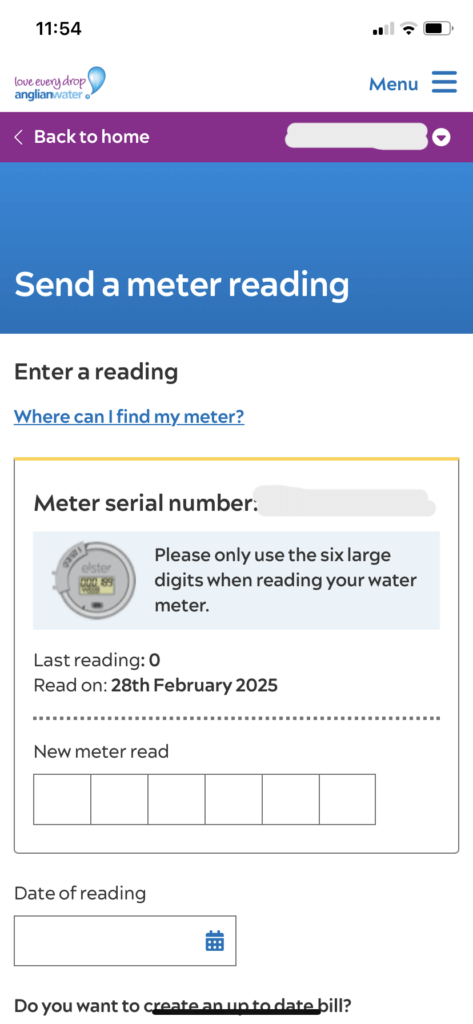
Every time I replace the salt blocks in my water softener, I note the reading on the water meter and log it, typically after 26 days I use between 8 to 9 m3 of water, however, when I checked on the 1st December, I had only used 1.6m3, so something was wrong with the meter in the street.
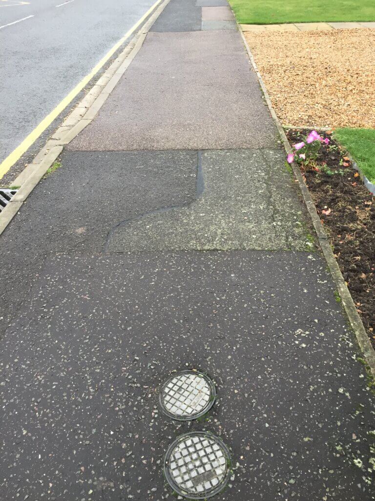
Two meter covers, the lower one is to my property.
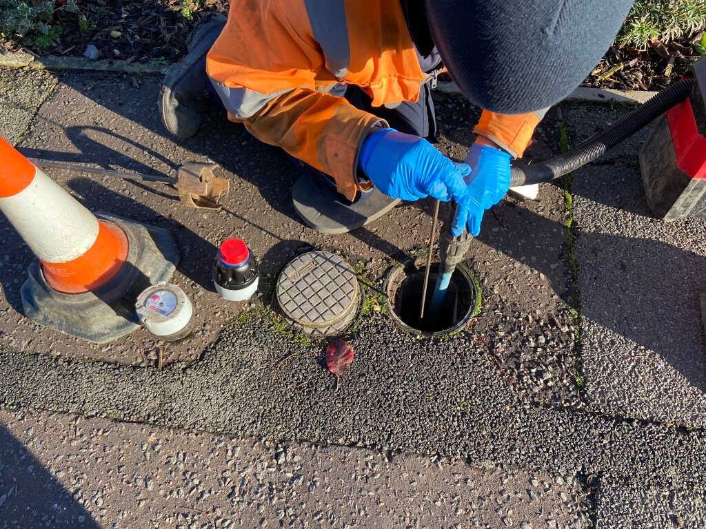
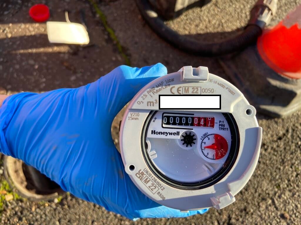
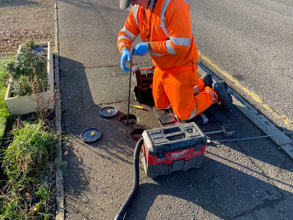
After reporting the low reading to Anglian Water on the 1st December, Jonathan the engineer called on the 7th December to replace the meter, I assumed that the meter would need to be dug up and replaced, but when I was told it will take 5 minutes, I thought I’d take a few pictures.
His first job was to insert a special key into the upstream isolating valve, and turned the water off feeding the meter, he then used the tool in the picture to slide over the meter body and simply unscrew it from the fixed base.
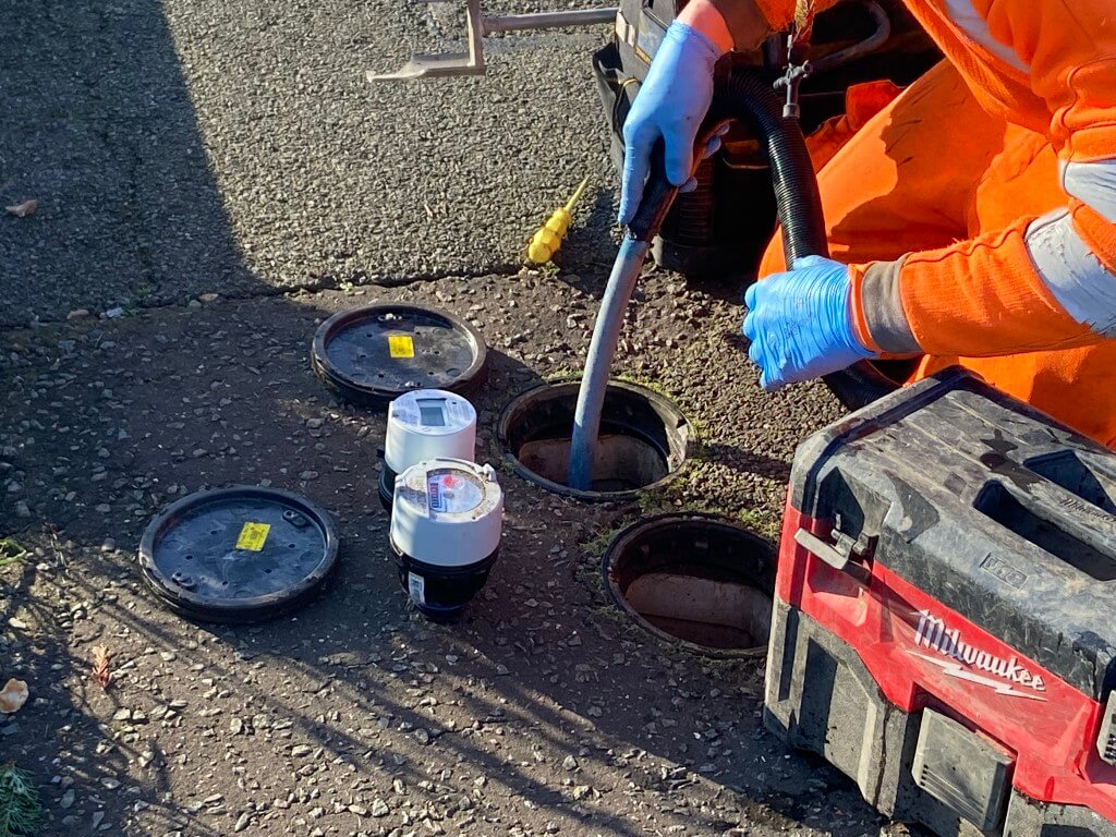
With the meter removed, he cracked open the isolating valve and using a wet vac, flushed out the meter body with fresh water incase their was any debris which could damage the new meter.
Once the flushing was complete, the new meter with the red protective thread cap removed was screwed into place and the water deisolated.
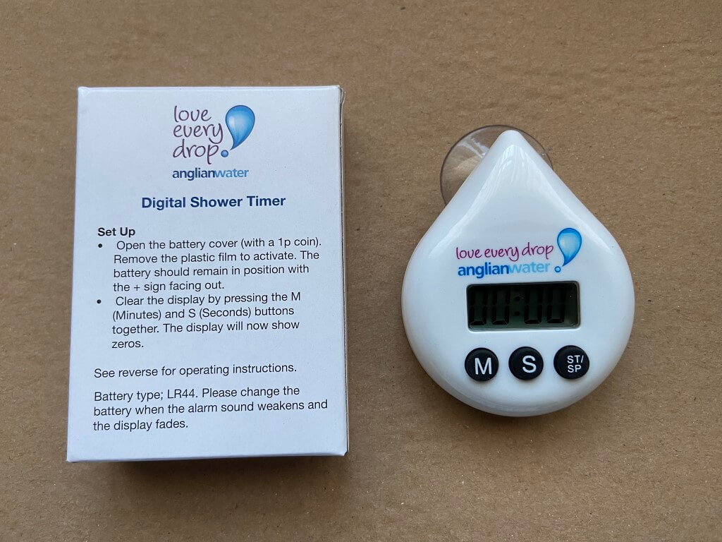
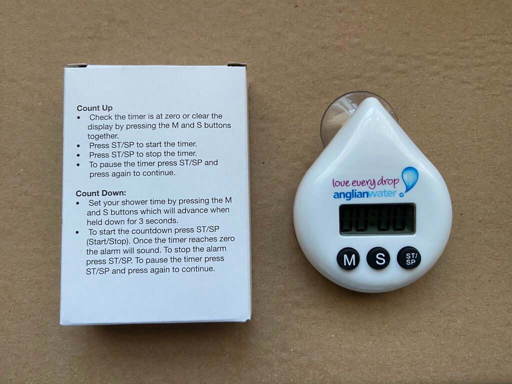
I was asked to test that the water was now working in the house, which it was, and he left after checking for meter leaks, but not before giving me a water saving pack which was much appreciated, especially the gadget to set your shower target duration in order to preserve water.
I have to note that with every interaction with Anglian Water, I have always found them to be professional and courteous.
Smart Meter Installation
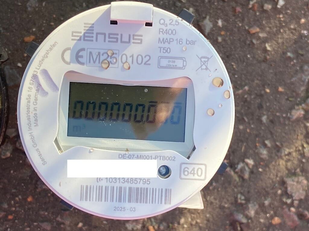
28 February 2025 – I have previously contacted Anglian Water regarding a smart water meter and checked on there roll out website a number of times, but to no avail, then out of the blue, Robbie from Anglian Water turns up to upgrade all the meters in my town to smart meters 🙂
Water being isolated to enable the removal of the old meter.
Robbie clearing any debris before installing the new meter, (furthest away in the picture).
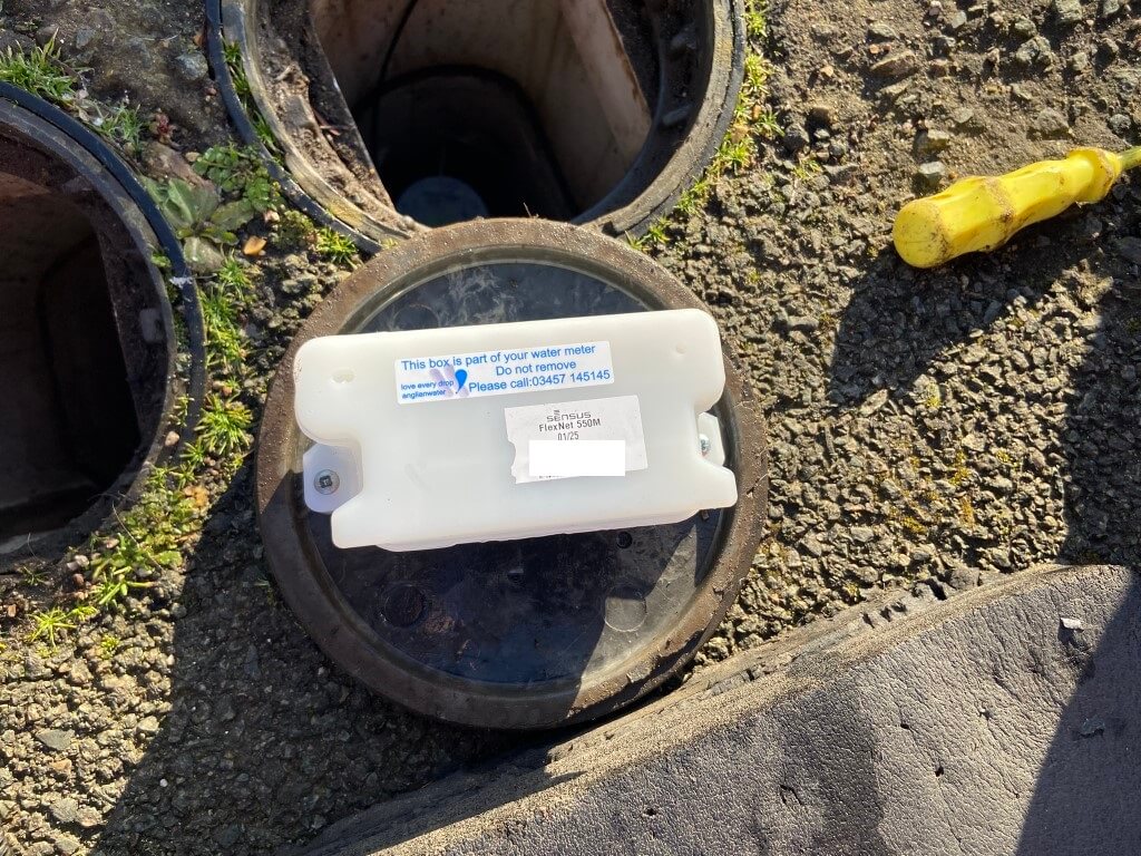
Sensus Flexnet 550M wireless repeater was screwed to the plastic meter cover, this is needed to ensure a strong signal is being sent to the base station from the smart meter due to its depth below the surface.
I was told I will be notified when the meter data is live and that the updates are hourly on my Anglian Water app, another plus is that leak detection can be reported to you, the above image shows that the app has been updated since the install was done a couple of hours earlier.
Approximately 3 weeks after installation I received notification from Anglian Water that my smart meter was now live on my app, true enough it was, but its 24 hours behind, rather than actually live hourly consumption.
Maybe once they have worked out an API to scrape the data, I will be able to use Home Assistant to record usage.
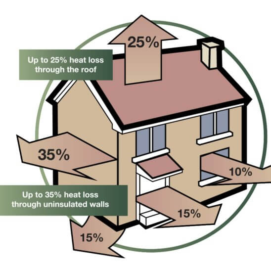
My existing Vaillant central heating system boiler has been installed since 2003 and performs very well, however, when it is time to upgrade, I want to make sure the boiler and radiators have been correctly sized for a central heating design flow temperature of 550C (Δ t30), this flow temperature will be in compliance with Part L of the Building Regulations 2021.
For context, my existing system boiler is on a Honeywell ‘S’ plan, meaning I have two independently controlled motorised valves, one directs the boilers heated water to the radiators, whilst the other valve supplies the same temperature water to the unvented hot water cylinders indirect heating coil.
I have used recommended design temperatures for each room, this varies based on the function of the room and as I’m located in East Anglia, my CIBSE design outside temperature is -3oC.
Although the calculated heat loss minimum is -3c, as you can see, it does get colder.
So, my CIBSE Lounge design temperature is 21oC at an outside temperature of -3oC, therefore, my differential temperature is 24oC, meaning I can heat my room to 21oC, overcoming losses, even when its -3 oC outside.
Why Bother!
Good question.
Radiators are designed to give out a certain amount of heat (measured in Watts), when the water flow temperature in to the radiator is 75oC and the exit water temperature of the water from the radiator is 65oC, so 10oC has been dropped across the radiator.
For ease, lets say the water temperature across the radiator is in the middle of 75oC & 65oC making it 70oC, if the room is at 20oC, then 70oC – 20oC = 50oC, this is the Delta Temperature or Δ t50.
So what! Well at Δ t50 my bedroom radiator for example, gives out 1106 Watts, if my flow temperature is reduced to 55oC or Δ t30 then the same radiator will only give out 563 Watts of heat energy and as my bedroom needs 885 Watts to keep me warm, I won’t be a happy bunny.
The heat loss process proves if your existing radiators are adequate or not at reduced flow temperatures for each specific room in the house.
Heat Loss Process
Firstly I’m not a heat loss expert, this is an amateur blog on how I did mine as accurately* as I could, if you spot an error, please let me know as I’m always learning.
*Note- I have made a number of assumptions as I’m unsure of how the ground floor was constructed for example, however, I have used the 1991 version of Part L as my guide, as this was the current version when the house was constructed.
The key document for heating system design including calculation losses is the CIBSE, HVDH Domestic heating design guide (2021) which is downloadable for a fee (was £20).
The CIBSE guide includes recommended design temperatures based on the use of the room, for example a lounge temperature is 21oC also in the guide is common building materials and constructing type heat losses.
I also downloaded a free Heat Loss Excel Workbook from MCS and guidance on U-Values for the workbook are HERE.
The MCS Excel workbook requires detailed room, by room information to be gathered, including floor, ceiling and wall construction, I found the workbook to be excellent and well worth the effort of completing.
I decided to create my own spreadsheet so I can tailor it to take into account wall types changing on the same wall.
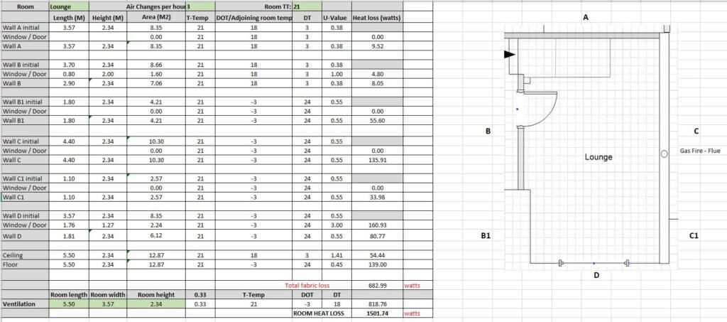
In the lounge for example wall ‘B’ separates the Hall and the wall is made from lightweight block, whilst wall ‘B1’ is an outside wall made from different materials with different thermal losses.
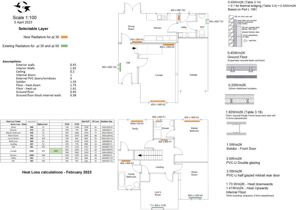
Using the spreadsheet, the lounge heat loss is calculated at 1502 Watts, this is quite high due to the gas fires flue increasing ventilation losses, however, my existing radiators give out 1973 Watts, so all is good.
With a new boiler at a flow temperature of 55oC, the outputs will be 997 Watts, not so good!
I did the same process for all the rooms using the drawing below.
Using Visio, I drew a scaled drawing and transferred all the measurements, this made the heat loss process easier as I could tick off the different materials and where they were used, ironically the MCS spreadsheet came out with very similar numbers to my spreadsheet, even though I drilled right down in to part-wall construction and factored heat gain/loss to adjacent rooms.
What was the outcome.
I learned that the total heat losses for my property is worst case 7980W (airing on the side of caution), and best case of 6808W, I have a 24kW boiler which does not have the ability to modulate the gas valve, so when it fires up, I get 24kW of heat output whether I need it or not.
I do however need a minimum of 17.3kW to heat 170 litres of water in my unvented hot water cylinder, this means my new boiler will need an output of 18kW to heat my volume of water in 30 minutes.
Of the 13 radiators, I will need to increase in size 9 of them to compensate for the lower flow temperature, also I will need to factor a larger expansion vessel (12 litres), due to the increased heating system water volume as a result of the larger capacity radiators.
This exercise enabled me to have an informed boiler wish list:
System Boiler to have an output of 18kW,
Boiler to have Domestic Priority Hot Water,
Boiler to have an acceptable low kW gas modulation,
Boiler to modulate flow temperature on weather compensation.
Armed with this information, I can start to swop out existing radiators and make plumbing additions ready for a gas safe engineer to change to boiler, my pre-works will save him/her time and me money.
Update 5 April 2023
Required radiators have been updated, I chose Stelrad radiators as they are a well know and trusted brand, the only radiator which wasn’t Stelrad was for the Utility as they don’t do the size of 400 x 900 Type 22 (K2), so Kartell K.Rad was used.
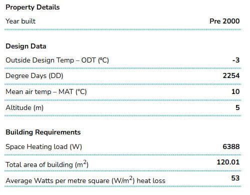
Out of interest I used the free version of Heatpunk heat loss software which I found very easy to use after watching the YouTube tutorials.
The Heatpunk heat loss came out at 6388W as opposed to my worst case spreadsheet values of 7980W, If I had used more conservative values for the kitchen and lounge, my value would reduce to 6808W, so only 420W out as a comparison.
Heatpunk generates a number of reports and the links are for the Technical Report and Heat Pump Design Report for my property as examples.
Note – I have completed details for a heat pump and hot water cylinder in order to generate a complete report, I’ve no intention of changing my gas boiler any time soon 🙂
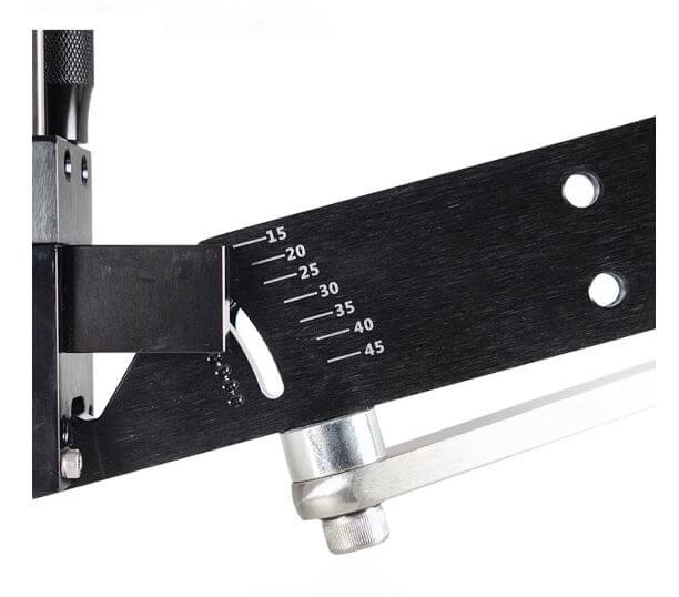
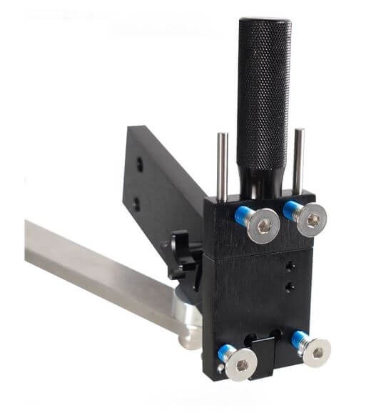
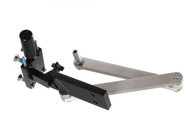
I have always sharpened my lawn mower blade with a wet wheel grinding stone but the problem was getting an accurate cutting angle on the blade, looking around for a better solution, I came across the All American Sharpener which looked perfect.
The appeal of this sharpener was the repeatability/accuracy of the blade grinding process and the fact that it makes use of an angle grinder that most DIYs already have.
The bad news is the cost, the current price on Amazon in the UK is £416.75 (2nd Nov 22) for a genuine All American Sharpener.
Being well outside my budget for an amateur, I went straight to eBay and for £56.97, bought a Model 5005 product which looked like it was based on the genuine version of the tool, however, its design was not simply not functional and I returned it for a refund.
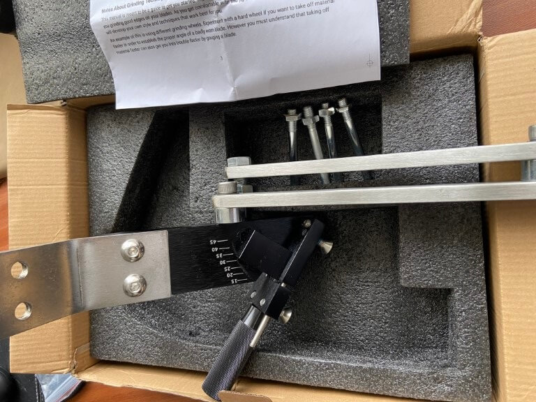
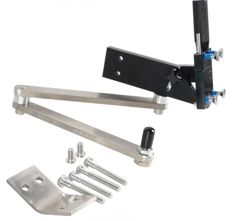
I ordered this on the 18th Oct 22 arriving 16 days later on the 2nd Nov 22 and I was immediately impressed with the quality of packaging and tool construction, the unit weighed in at 2.3kg.
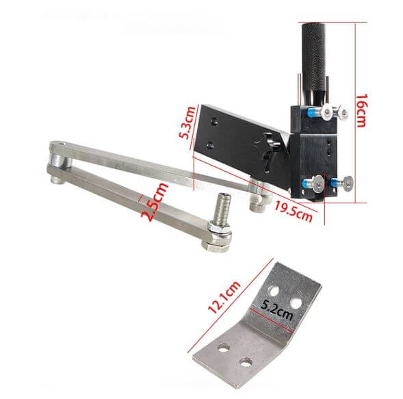
The sharpener came with all the parts I expected, so very happy, the things not provided are the fixing bolts to secure the unit to a suitable surface, (in my case I’m using a vice), a 5.5mm Allen key to tighten the mounting bracket to the sharpener and an 8mm Allen key to relax the arm joints.
Flapper discs are recommended and the one I used was 80 grit which was bought from Aldi in an assorted pack for £4.99.
The sharpeners angle should be set to 300 for optimal cutting and due to the sharpeners design, the angle grinders cutting edge will now be perfectly aligned to allow the defined angle to be ground into the blade by simply moving the angle grinder up and down the blade which is the only movement the articulated arms allow.
Setup didn’t take long and after a few grinder passes, I had a nice sharp edges on the blade.
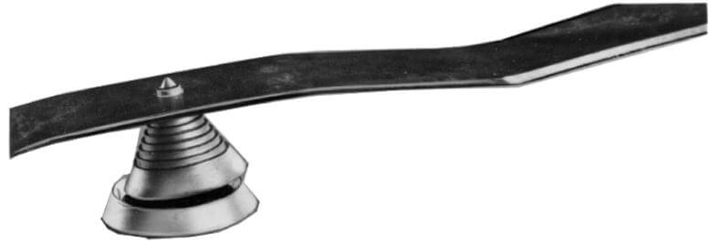
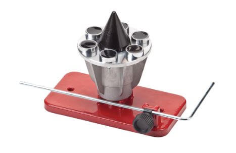
Once the blade was ground, I checked the blade for balance with a cheap and cheerful gadget, unfortunately the blade on my Titan Mower has an oval hole, this means getting the blade centered on the cone is difficult.
As the cone balancer was basically not really compatible with my blades oblong mounting hole, I bought from Amazon a Oregon blade balancer.
I have subsequently found out that it is not possible to get replacement blades for the Titan TTB833LWM 230v corded mower purchased from Screwfix, if I’d known this, I wouldn’t have bought the mower.
Conclusion
Obviously I would like to support the original developers of the blade sharpening product, but the UK price point makes this unaffordable to me, I therefore took a chance with the Chinese marketplace, Aliexpress.
It must be said that the quality of the sharpener is superb, all the attachments were included and I’m very impressed with the whole transaction, postage was more expensive than the tool itself, but nevertheless, I’m very happy with my purchase.
The Oregon blade balancer is a bit of self indulgence, the construction is solid and the rotation of the cone is very smooth, this will definitely last a lifetime
Now I have the time, I thought I would create what essentially is a home Operation and Maintenance, locally hosted webserved interactive manual.
The advantage of this is that all information relating to the house, individual rooms or equipment is held in one place, locally accessible on my home network either on my Desktop or mobile/ipad.
The starting block is my Synology Diskstation DS220+ Network Attached Storage (NAS) device;
The DS220+ has an inbuild webserver, so it was fairly easy to upload web pages created using the free version of Microsoft Expression Web 4, this is great software as it allows for the creation of image hotspot links to be embedded in pages.
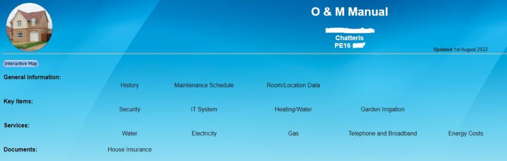
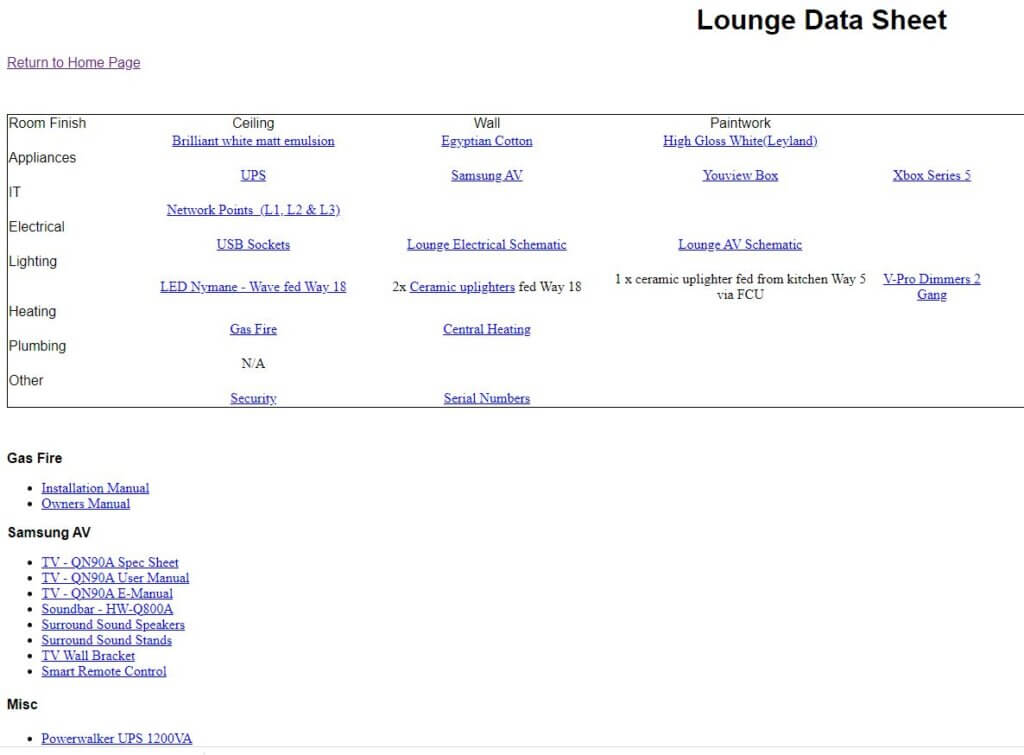
The main landing page is shown at the top of this blog, I can either click on the general description headings or click on the house image and an interactive view of the house will open:
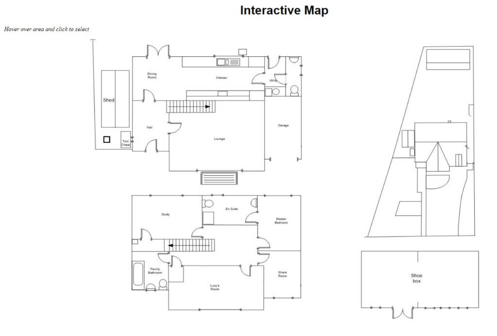
On the webserved image, as the mouse hovers over an area, this becomes ‘clickable’, on clicking, this takes you to the specific area of interest, as an example, hovering and clicking on the Lounge take me to:
This gives me access to room finishes, equipment manuals, serial number records and user guides, TV wiring, room electrical schematics and further links to specific, more detailed information of broader areas, such as the security system and central heating for example.
QR Code Labels
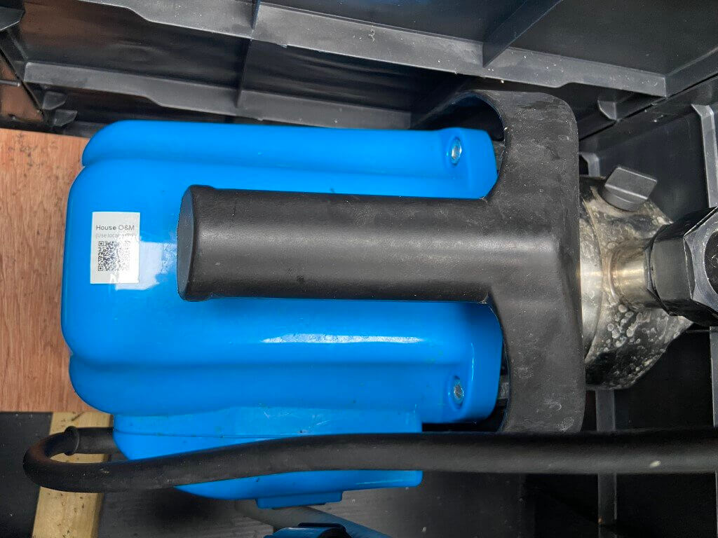
To enable quick access to information held on the webserver, I’ve used a number of QR code labels, to illustrate this, the pump for my irrigation system has a QR Code attached which will take you to the pumps manual:
Viewing the QR Code using a phone or ipad camera will automatically open the link to the webfile.
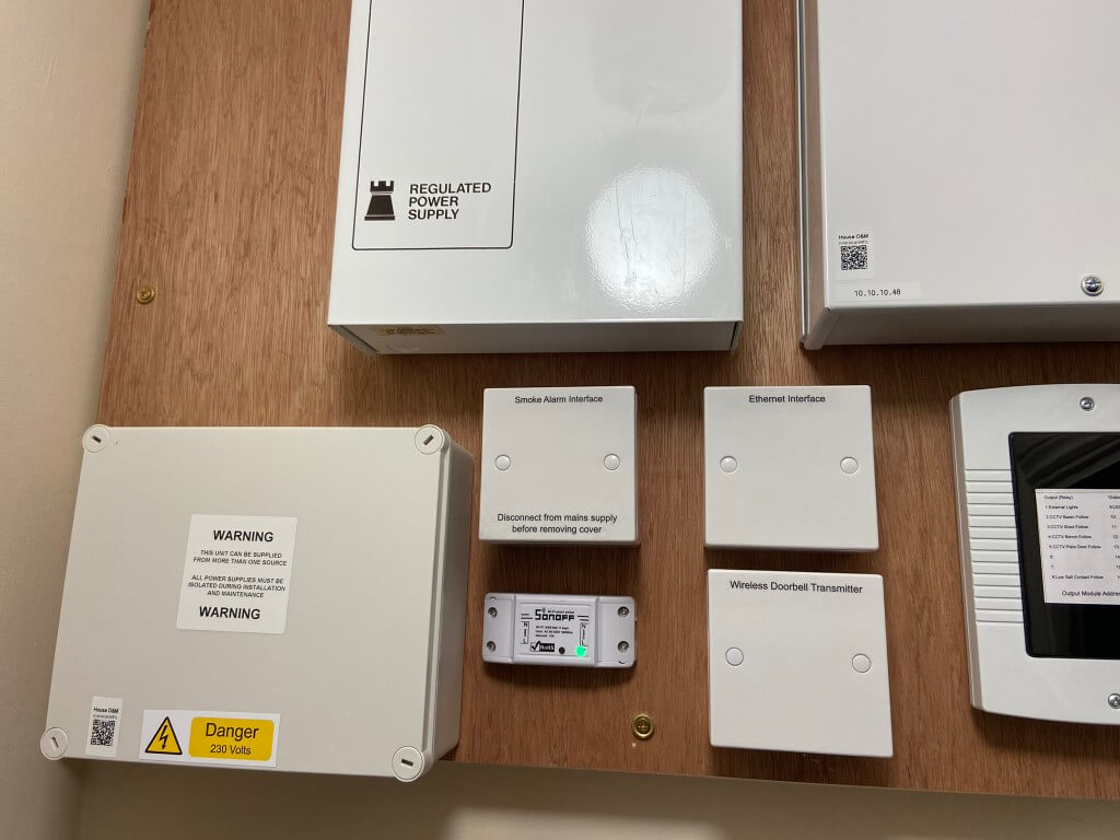
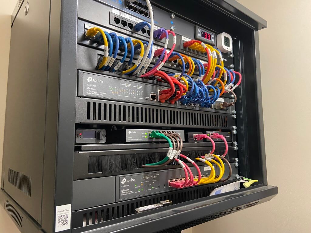
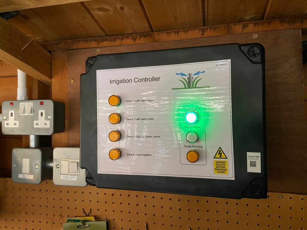
For more integrated projects, QR Codes are attached to the equipment linking to detailed, multi linked page/s:
Irrigation system is used in this example –
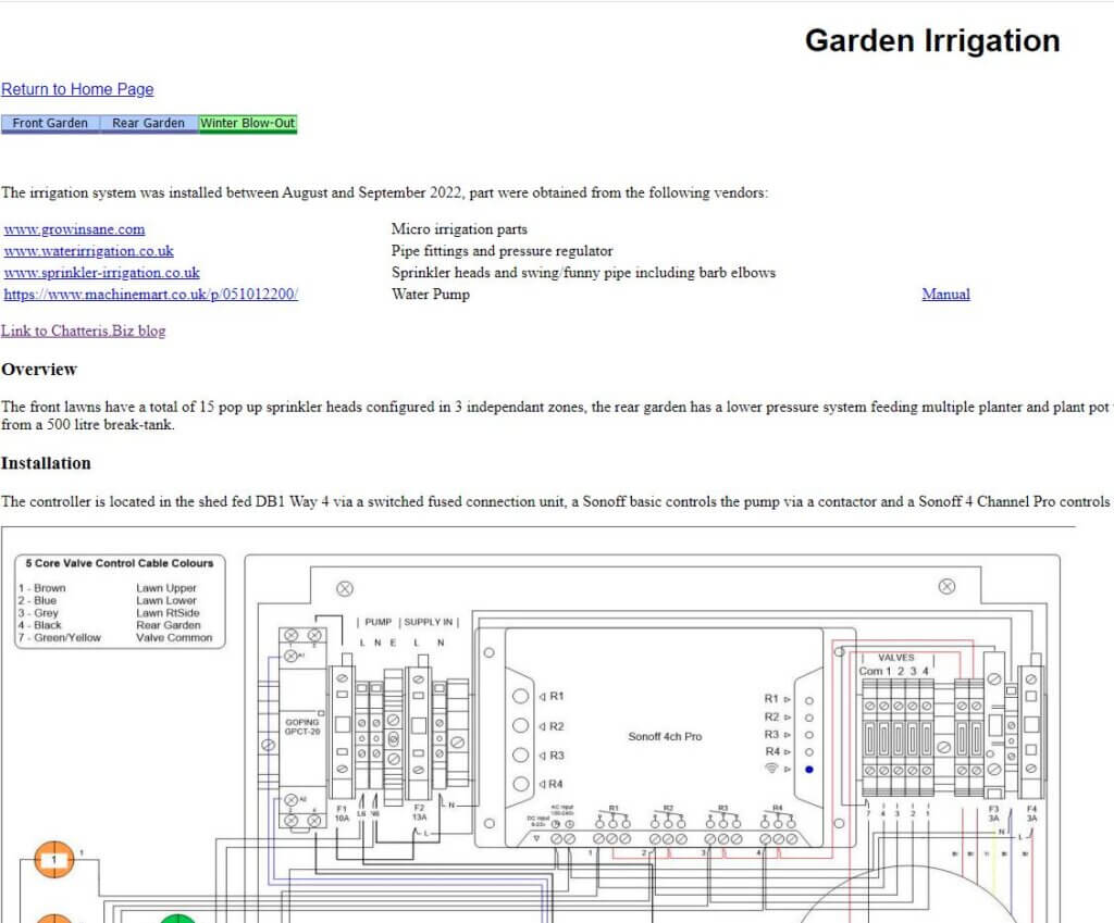
The controllers QR Code links directly to the Garden Irrigation page –
This linking to detailed information is incredibly useful to document on how things are configured, interconnected or interdependencies from a technical perspective, or more simply to store data sheets and supplier details.
Producing QR Code Labels
Small asset linking QR code labels are used:
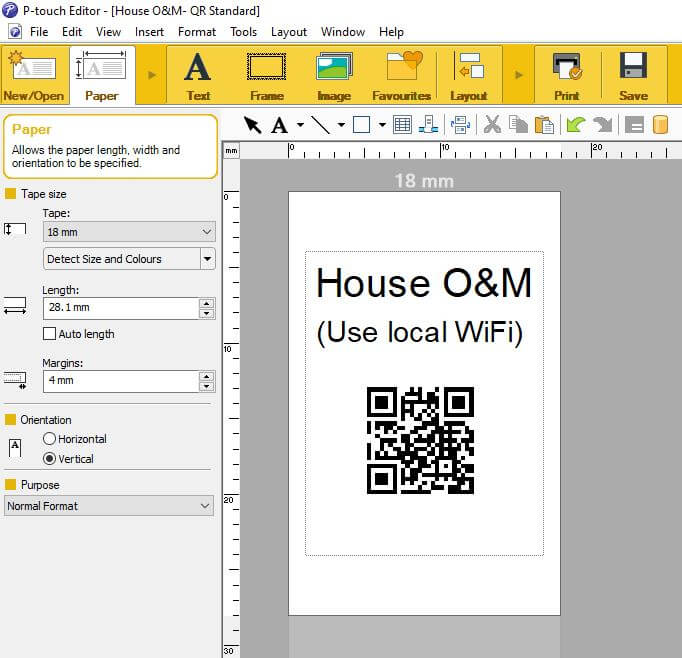
The Brother P-Touch E550W printer has the ability to print a huge array of different labels, for asset labeling I use 18mm White Tape connecting the E550W printer to my PC using P-Touch free editing software.
The printer can connect via Wi-Fi or Direct USB cable to the software.
The above QR Code will take you to my other site, Chatteris Weather.
In P-Touch Editor software, select ‘Insert’ > ‘Bar Code’ with protocol ‘QR Code’ selected.
Within the QR Code software window, you simply paste the link in the ‘Input’ window and press save and print.
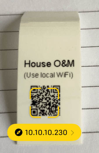
Viewing the QR code with a phone camera, a yellow box will appear with a partial link description, clicking in the yellow box will take you to the site originally entered in the ‘Input’ box.
Example display of correctly read QR Code
Conclusion – The use of a quick and easy way to access information makes life very easy, generating and maintaining the data does take time, but the information is available to anyone at anytime who needs it, (given they have the appropriate access rights to the Wi-Fi password).
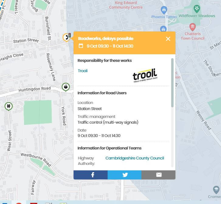
29 September 2022 – Trooli scheduled works keeps coming up on One-Network but their is no sign of any activity yet.
4 October 2023 – Trooli scheduled works in Station Street, maybe its getting closer 🙂
8 January 2024 – Infrastructure work started!
Trooli
Well 2022 is a very busy year for broadband in Chatteris, Openreach now deliver Ultrafast broadband with fibre to the premises (FTTP), Virgin Media are expanding their 2017 network in the town to include homes and business not previously included, Netomnia started work in May to lay down its own independent FTTP infrastructure and now Trooli are making a presence all with their own independent network.
What is interesting is that Trooli have an agreement with UK Power Networks to run their fibre optic cables across certain power poles, enabling them to reach many more customers. The write up on this can be found HERE.
I just wonder where all these customers are coming from to give payback on the huge investment these companies are outlaying?
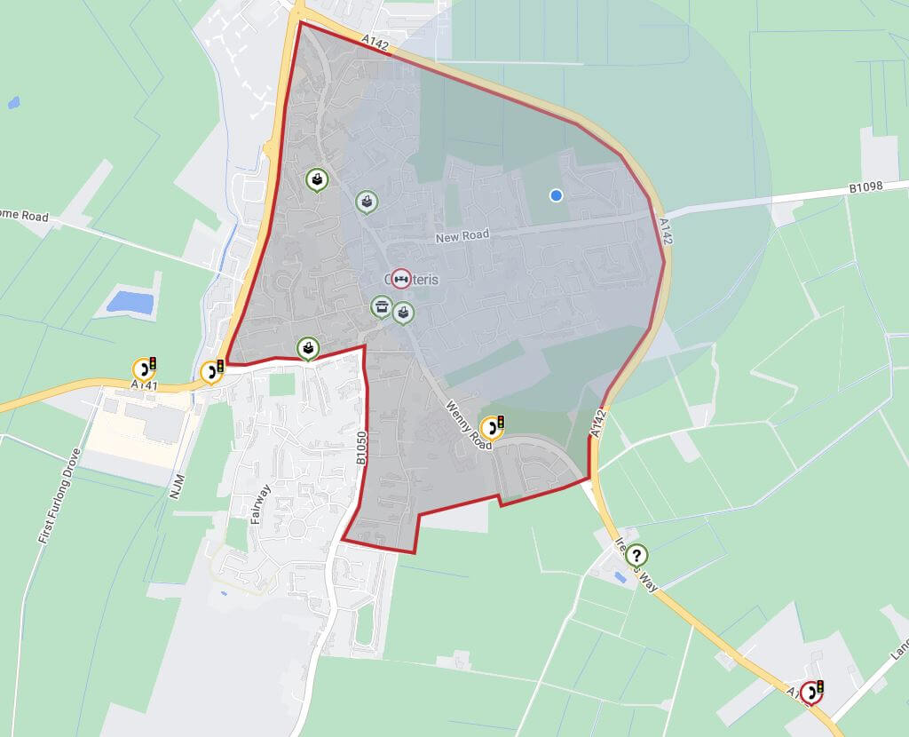
Screen grab from www.one-network 10 Aug 2022
Work Commenced – 8th Jan 24
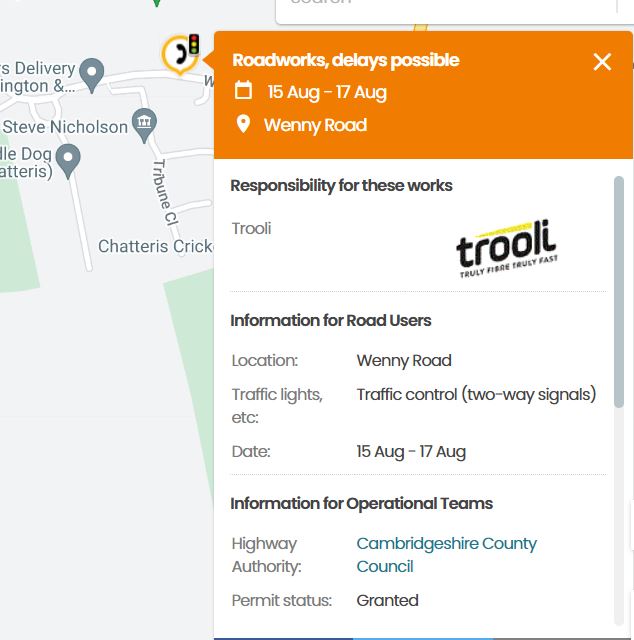
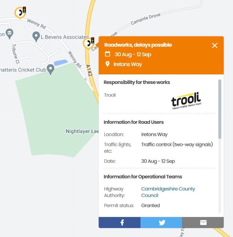
Checking on Onenetwork, Trooli works were highlighted, (telephone symbol), from the 8th to 15th Jan at:
Wenny Road
Old Huntingdon Road
Huntingdon Road
Iretons Way
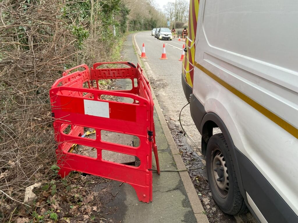
I knew that Trooli had been working in Sutton, so checked the Wenny Road location first as the fibre to Chatteris comes from there on route to Warboys, and saw the fibre engineers van, I obviously must have missed the earlier fibre pull from Sutton and the one on route to Warboys.
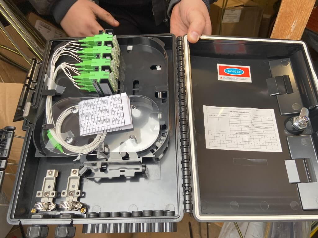
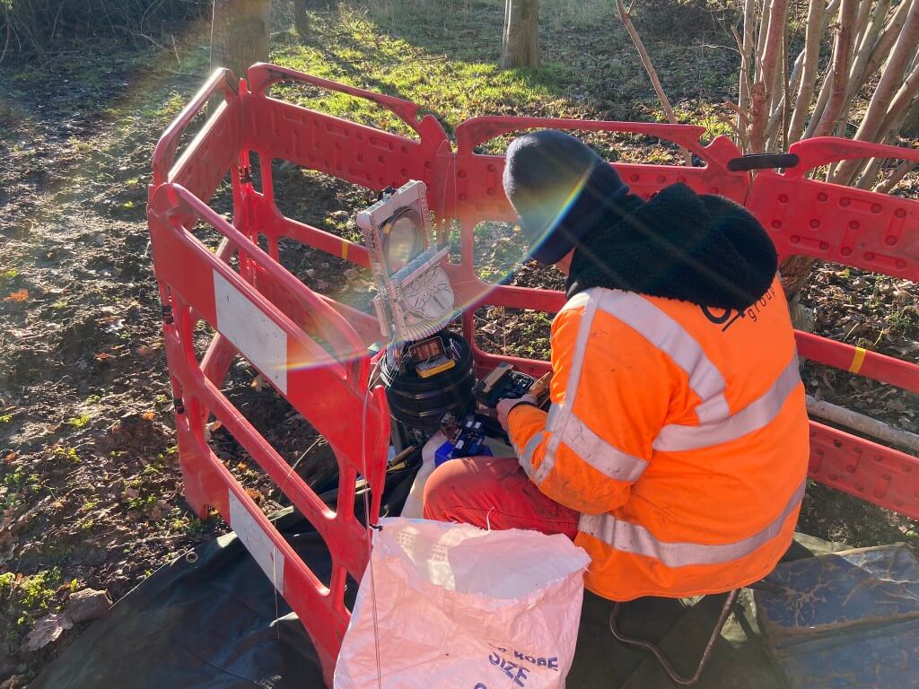
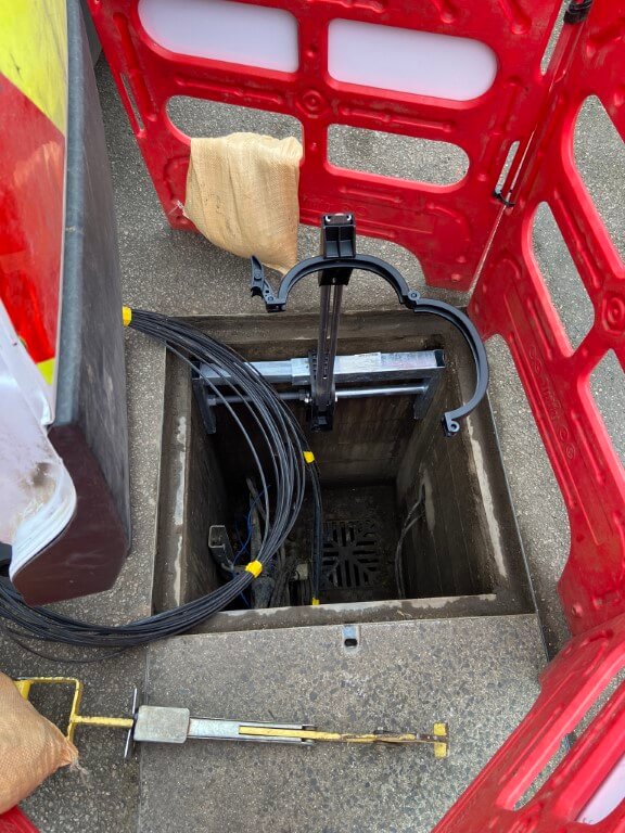
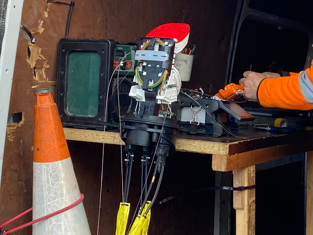
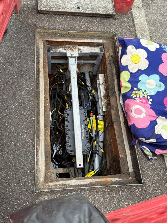
Chatting to the guy who was very cordial, he told me that a 48 core fibre runs from Sutton, and from this they splice off into either pole or footway box Connectorised Block Terminal which Trooli refer to as an ‘FPs’.
The lockable FP used has an inbuilt optical splitter, splitting a single fibre into 16 customer ports.
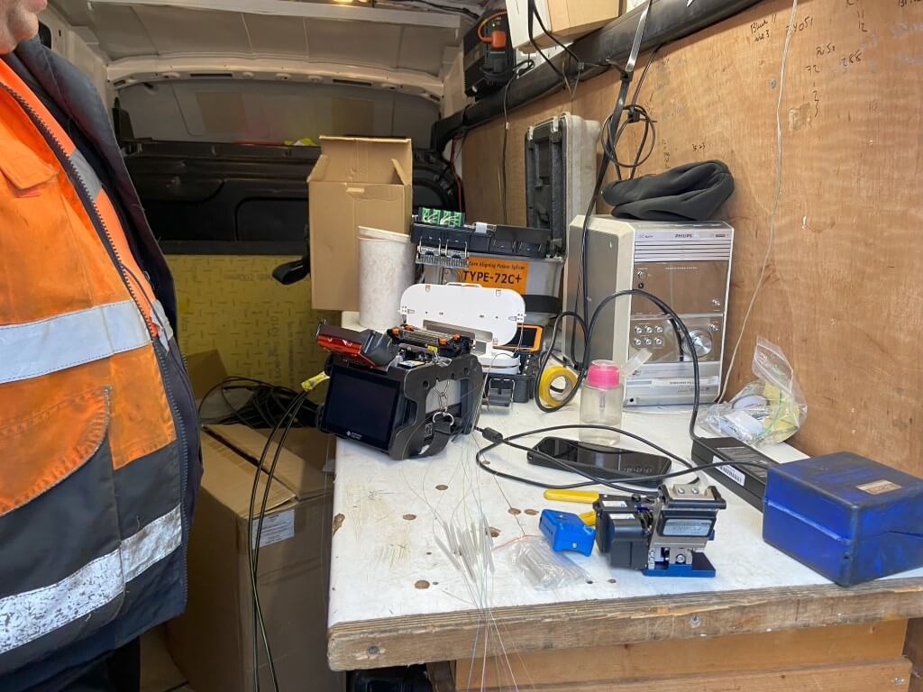
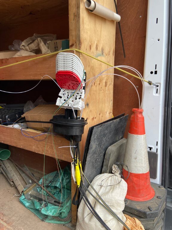
FP in the process of being spliced into the main trunk fibre before being placed into the footway box for customer connection at a later date.
In chatting, it appears, (at this stage of my understanding), that the Trooli topography is different to Netomnia or Openreach where they have either aggregation nodes or differing levels of fibre dissemination with plenty of spare fibres taken to the exchange.
Trooli seem to simply reduce the trunk fibre by one each time they connect a 16 port FP, I must be missing something otherwise that will give a maximum customer number of 46 x 16 = 736, leaving 2 fibres to pick up Warboys.
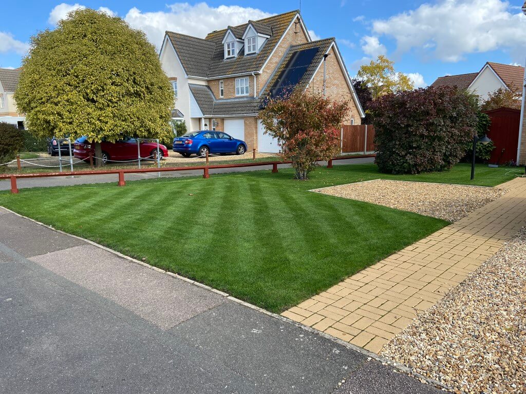
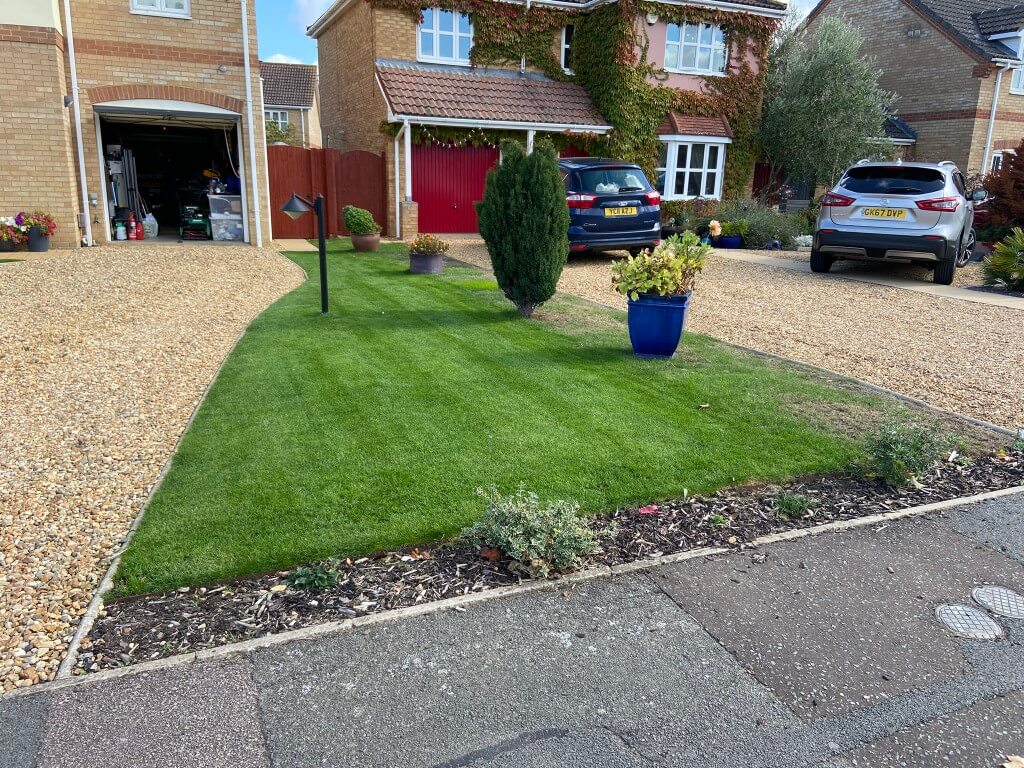
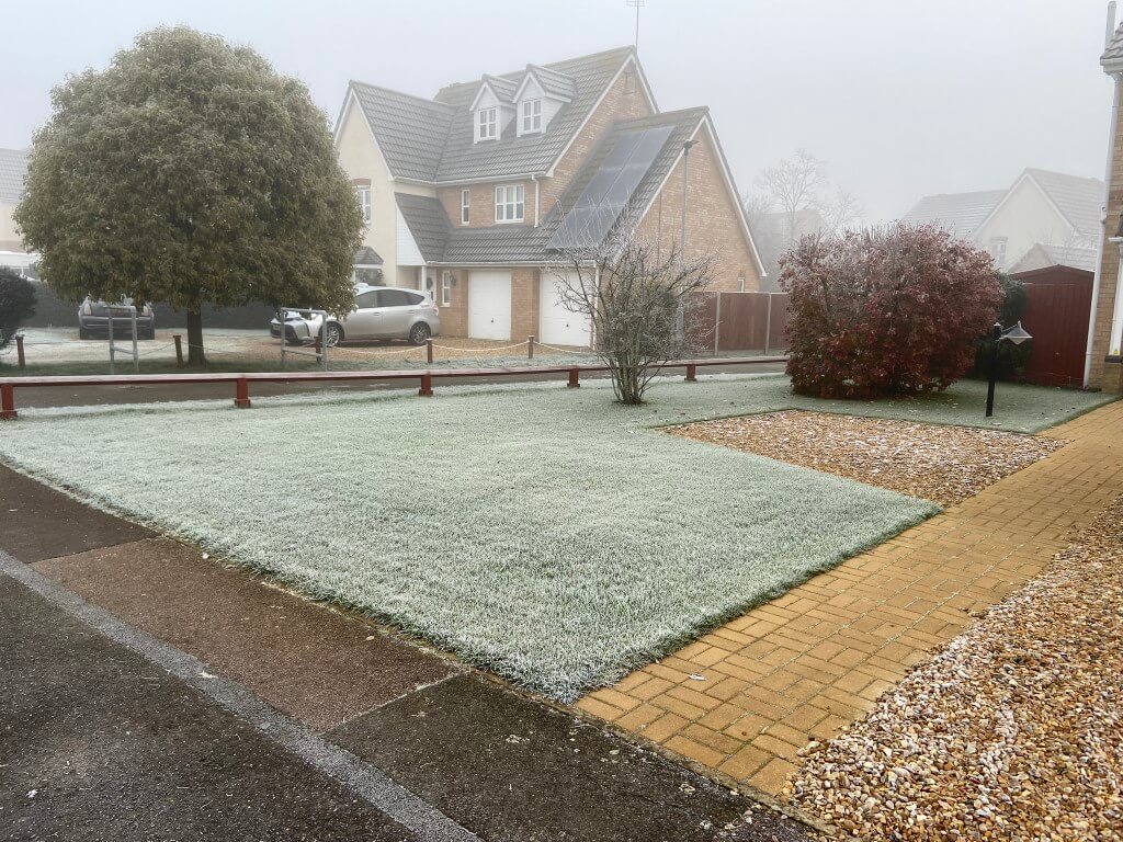
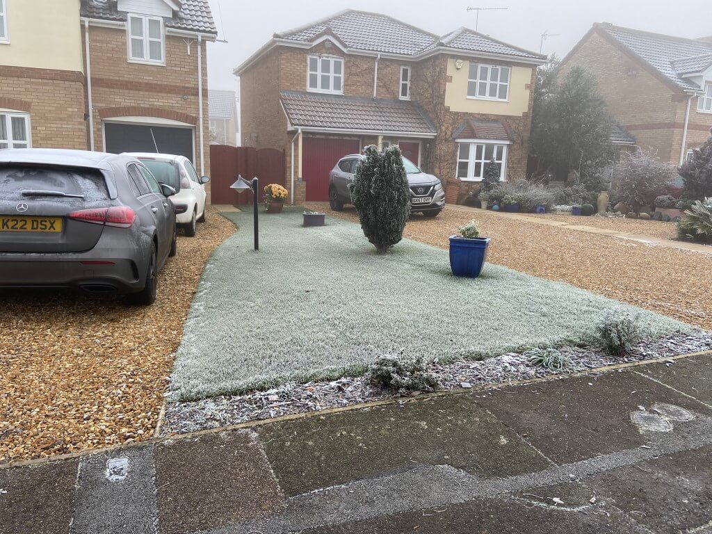
In 2022 I decided to invest some time and effort in getting the lawn in shape after years of neglect, so I followed a number of lawncare YouTubers, and with their advice, the lawn has never looked better even in winter.
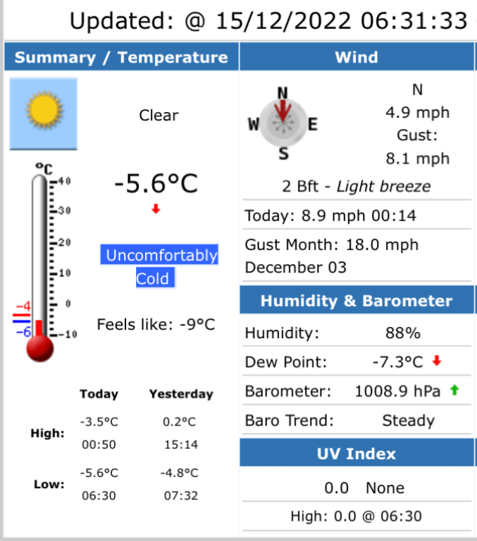
11/12/22 -4.2c
11/12/22 -4.2c
Unfortunately July 2022 was the hottest (currently) temperature ever recorded in the UK, and lawn watering was needed to keep the lawns (total area 117m2) in good shape, this took ages to do as my mains water pressure is poor and I have three separate sections of lawn, so the idea of an irrigation system tailored to my lawn layout was formed, I did have some experience, as I installed a simple Gardina pop-up sprinkler system at my last house in 1997, the difference being that the pipes were laid before the topsoil for the lawn.
I jumped back onto YouTube to start learning about irrigation system technicalities, and this blog is about how I installed my system.
Safety before you dig
As the irrigation pipes in my system needed to be buried rather than an above ground system and I’m digging near the pavement , I checked with Line Search before starting any works. This is a free online service, using this portal enables multiple interested parties to let you know if they have a pipe or cable near where you are working.
Not all companies are signed up to Line Search and during my hand digging I did exposed an Openreach telephone duct just inside my boundary which I did not expect!
Line Search did identify close proximity to Gas and Electricity services:
Anglian Water and Virgin Media services are also on my property but not identified by Line Search, I did make sure I knew the path these took before digging.
Irrigation Design
Fortunately a lot of information is readily available on the internet from manufactures, the two key players seem to be RainBird and Hunter, I downloaded the Hunter guide, so it made sense for me to deign around the guide and use their products.
Following the guide, I needed to find out was the static water pressure and water flow rate available to me, using a Toolstation pressure gauge connected to the outside tap which is fed directly of the incoming rising water main, here I recorded a spot reading of 2.7bar (40psi).
Chatteris is at the end of the water supply pipeline and the pressure can get quite low at times depending on upstream demand.
Flow rate was also measured at the outside tap, the flow rate was calculated at approximately 35 litres per minute, (timed bucket method, (I did confirm this later using a weir cup).
A quick glance at the Hunter products indicate that the optimal water pressure is 2.8 bar at the sprinkler head, therefore, I knew I would have to use a break-tank and pump to give me assured operation without dependency on the incoming water pressure.
Using Visio, I drew out a scaled drawing of the house and garden in order to work out the spray head coverage, pipe runs including pipe lengths and types of fittings needed.
It is important to work out pipe friction losses so that the pipes used are not undersized which would give an unacceptable pressure drop at the furthest sprinkler head, another consideration is water storage, you can’t connect a booster pump to an outside tap, if you have a stream, that’s perfect.
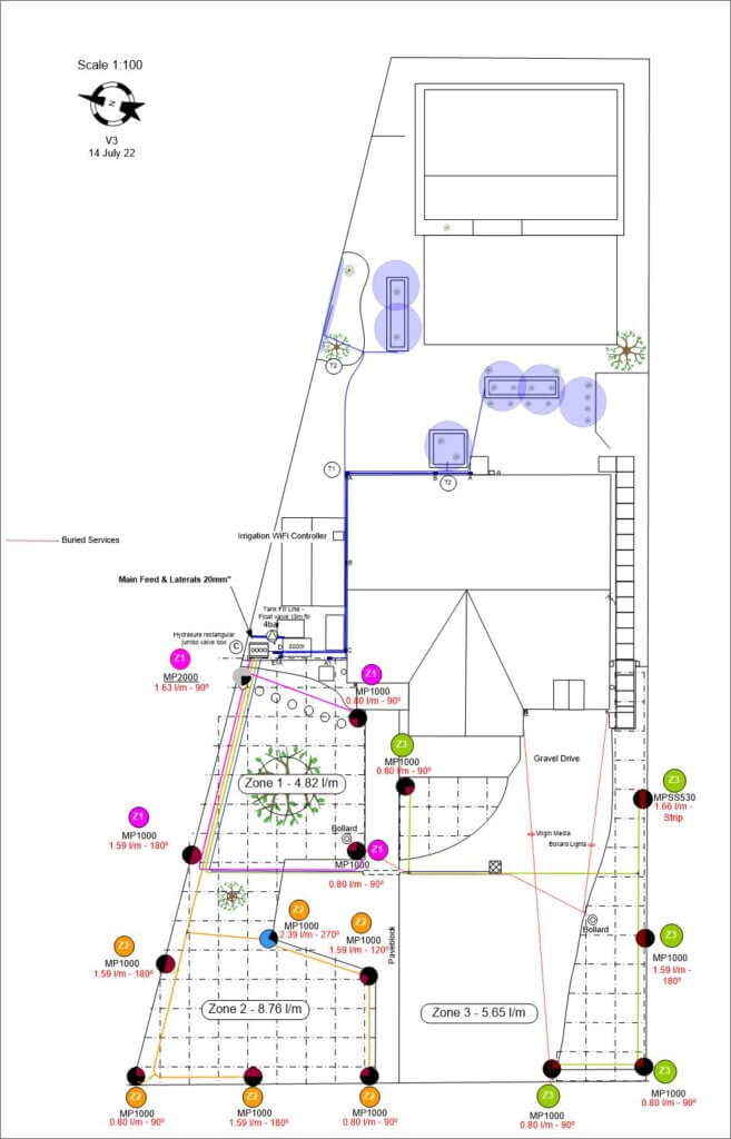
Digging Plan showing pipe routes, head placement and predicted water consumption, a full parts list can be extracted from this.
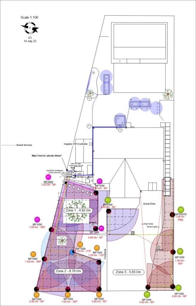
Drawing showing scaled spray coverage pattern confirming head types.
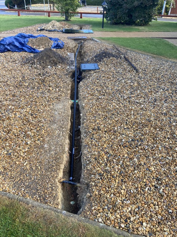
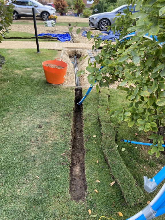
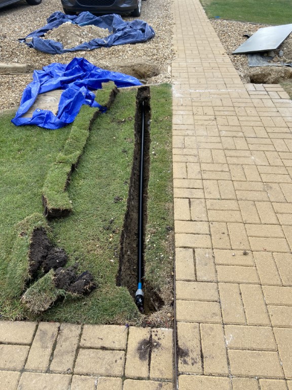
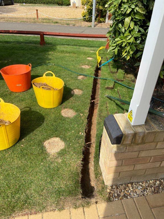
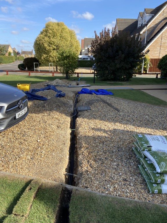
Drive dig underway, to Zone 3, the 20mm water pipe will be inside a 32mm duct (waste piping).
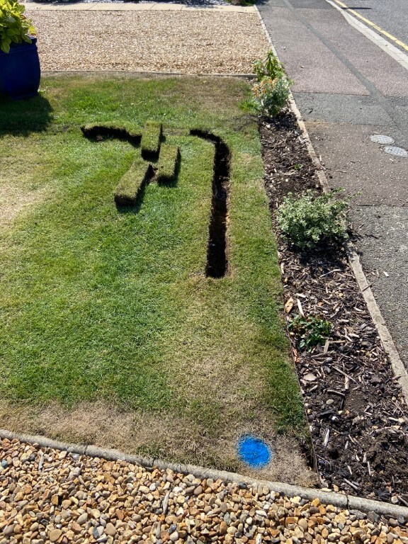
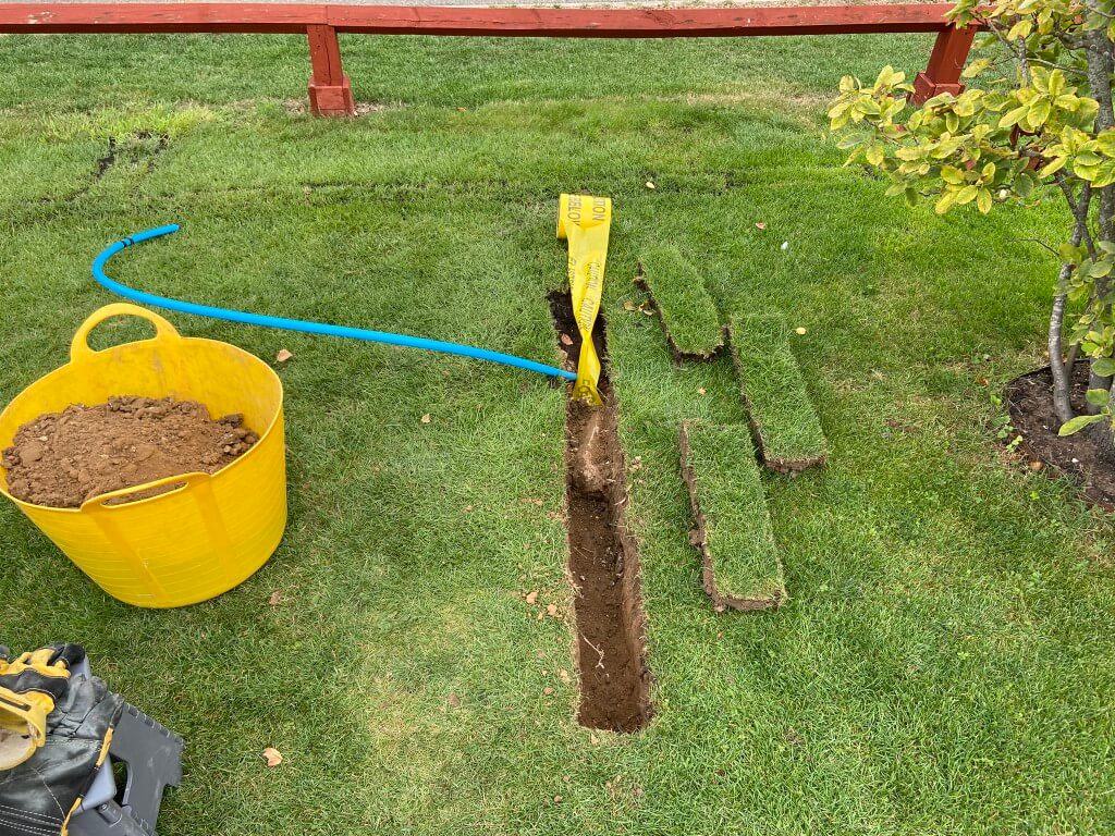
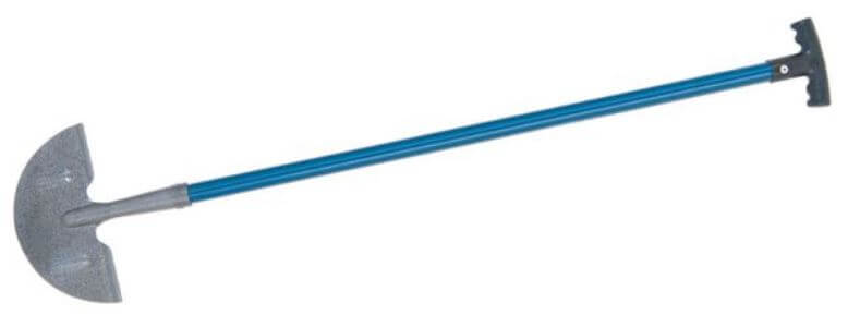
Digging Method: I first marked the sprinkler head locations on the lawn with a blue spray in positions from the dimensioned drawing, using string as a straight line to follow, the Lawn Edging Knife was used to cut a section of lawn approximately 12cm wide by 14cm long (4.3/4″x 14″), using the trenching shovel to get under the cut grass and levering it out for replacement later.
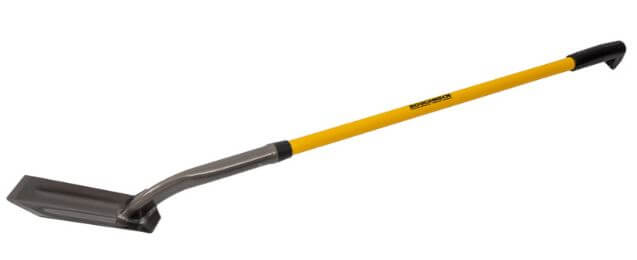
The width of the trenching shovel is 10cm (4″) about the same as the width of my boot which is handy for compacting the sand and soil later.
The depth of the trenching shovel is 20cm (8″) which in my case is adequate as water will be removed from the pipework over winter and also my aerators hollow tines are 12.5cm (5″) in length so I should avoid damaging the pipes when I aerate.
The builders left all sorts of bricks and debris everywhere before they put a layer of soil on top for the lawn, this made digging very difficult in places and the crowbar was superb in making a hard job easier.
Once the trench was cleared of stones and the trench bed flat, a layer of sharp sand was added to bed the pipe on, the pipe, even thought it was only 20mm needed pining down with stakes to keep it straight, a second layer of sharp sand was put on top of the pipe, then a marker warning tape followed by a bit more sharp sand, all compressed at each stage by a size 9 boot.
I used Levingtons essential top soil to fill the remaining trench, the first layer is compressed well down, the second and final layer is loosely laid so that when I place the cut turf back and ‘persuaded’ it down with the back of my shovel, the soil has somewhere to go.
When the turf was re-laid a sprinkling of top soil was added to fill the joins and brushed in, then liberally watered.
The tools used to dig were :
Silverline lawn edging knife
Roughneck trenching shovel 48″ from Toolstation – code 57538
Bulldog chisel and point crowbar, model 60-BCB60CP from Travis Perkins.
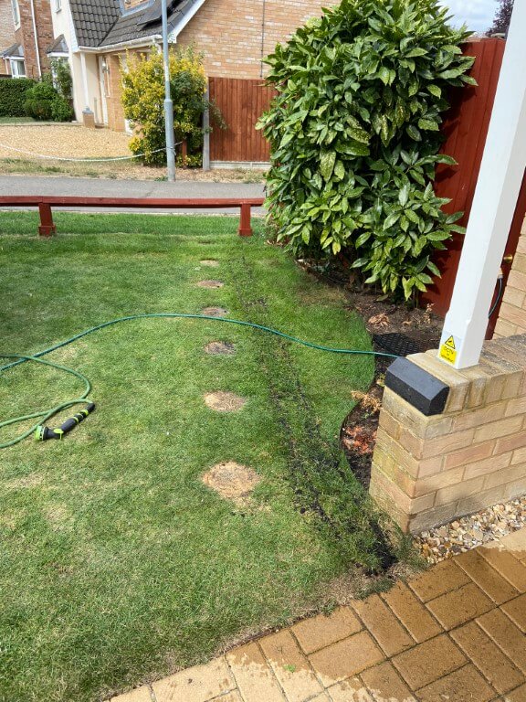
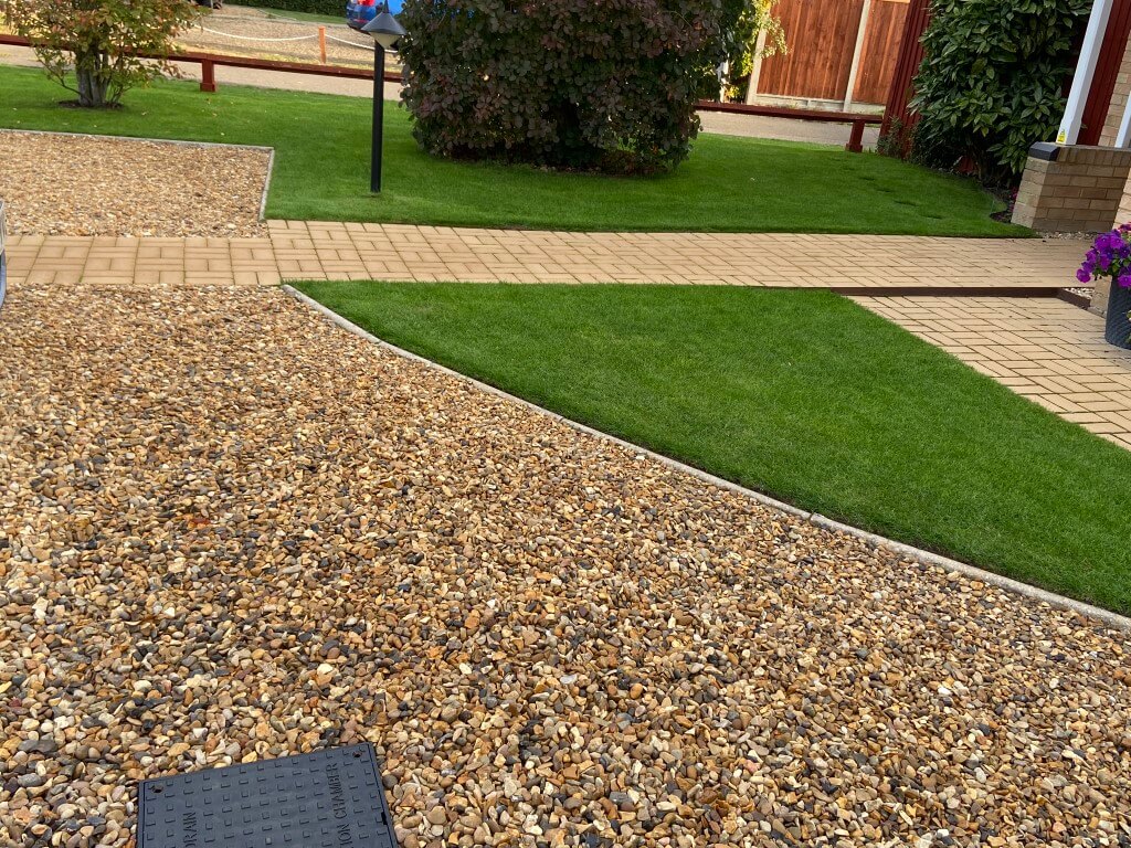
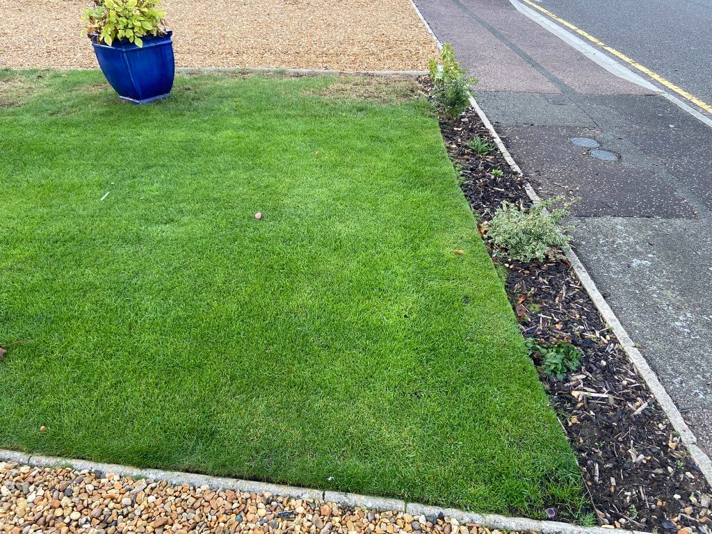
Above images are after a month of the sprinkler feed pipes being buried, showing just how resilient grass is.
Break-Tank & Pump
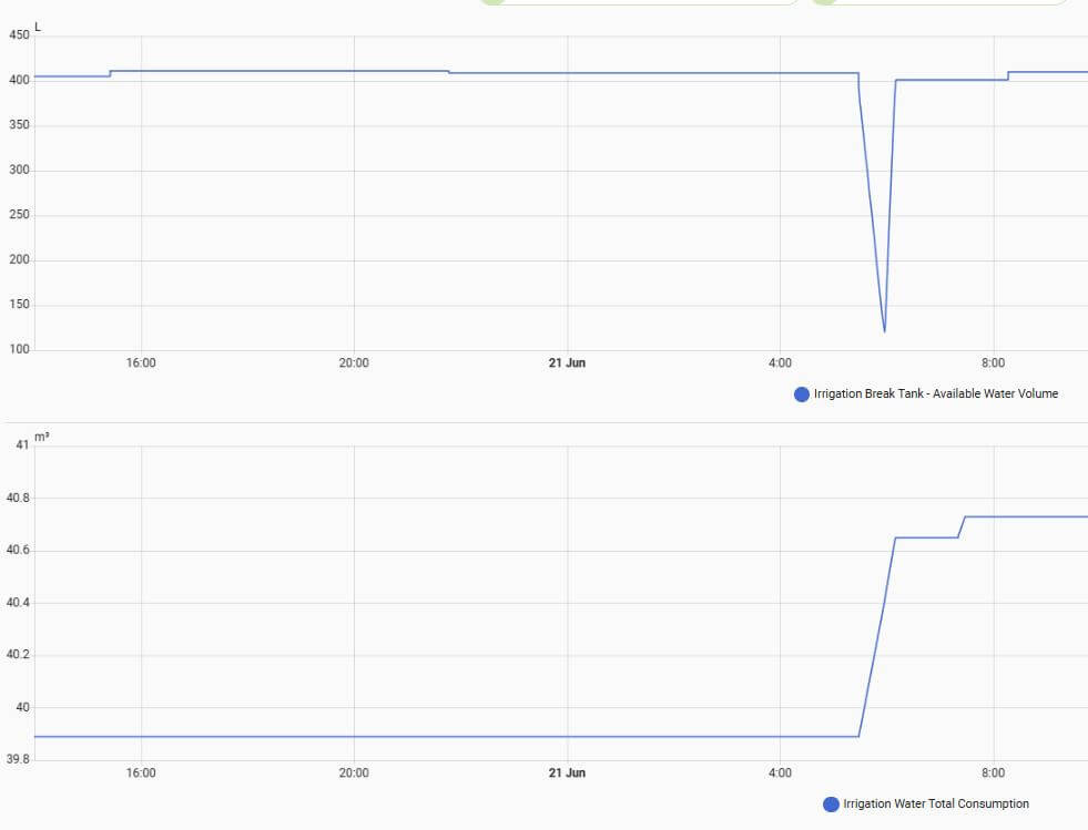
The volume of water storage available to you influences how many sprinkler heads you can have on at any one time and for how long before the the pump runs dry as it draws out more water than you are capable of putting back in it, this is a key limiting consideration for a watering schedule as a tank recovery time must be factored in.
The above graphs show Break-Tank water 30 minute watering cycle depletion and water filling volume during one irrigation cycles, as you can see, if I’d increased the watering cycle to, say, 45 minutes, the amount taken from the tank would exceed the tanks filling rate and the tanks low level detection would operate, stopping the pump.
A way to irrigate for longer periods whilst maintaining a working tank water level is to not have all watering zones on at the same time in my case, matching the water top-up with water draw.
The tank used is a Wydale Plastics 500 litre capacity upright water tank bought from Facebook Marketplace for £40 , this is perfect as my break-tank.
The term break-tank means their is no direct connection to the incoming water supply, the water filling float valve is positioned to maintain an air gap to eliminate any back-syphoning cross-contamination risks with the incoming drinking water supply, the height of the float valve within the tank, has reduced its capacity to approximately 430 litres.
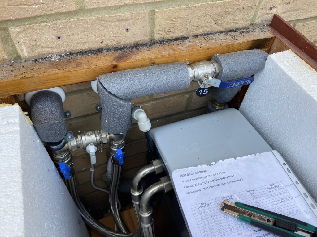
On my system, the break-tank can be filled in two ways, the primary method is via an independently metered 22mm supply from the incoming rising main to the 3/4″ float valve on the break-tank, this feed has a full bore isolating valve, double check valve and drain valve in-line for maintenance.
Valve 15 is the 22mm feed to the break-tank.
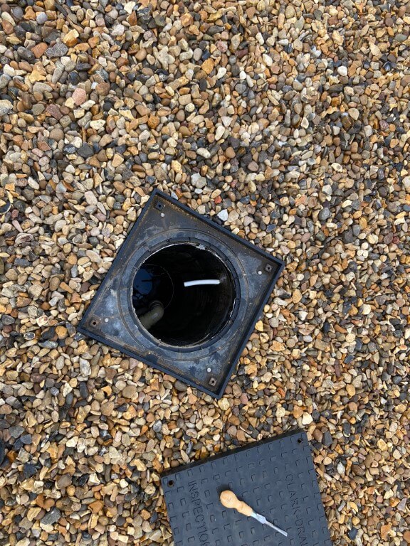
The second means of filling is by using the break-tank overflow line in reverse and pump the vehicle inspection pit water through this, (white 15mm pipe) via a ‘Y’ strainer at the tank end, in normal use, the break-tank overflow is into the pit.
Break-tank overflow into vehicle inspection pit, the pit holds 5,643 litres (1,241gallons), so very useful storage for pumping back to the break-tank, the grey pipe is from my gutters so I can harvest rain water.
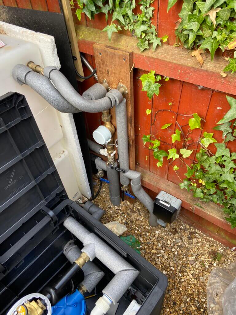
Break-tank in position sitting on 25mm polystyrene sheeting and plumbed in. Water is metered and electronically recorded.
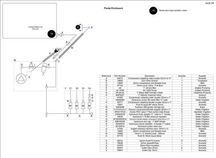
At the base of the break-tank is a 3/4″ full bore lever valve feeding a 22mm pipe with a 80 mesh ‘Y’ strainer fitted, the connection from the ‘Y’ filter to the pump suction line is with a 1″ flexible hose, connection to the pre-filer from the suction line is with a 1″ to 22mm adapting coupler (Screwfix 61955) .
The pre-filter is a Clarke PF1, 5 micron filter and comes with bowl removal spanner, the filters 1″ BSP pitch’s is quite course so a good sealant is required, I used a combination of PTFE tape and pipe thread seal (Screwfix 4373J).
I understand from Machine Mart who sell the Clarke pre-filter that replacement filter elements cannot be supplied.
Due to inadvertent prolonged running of the Clarke SPE1200SS original pump and its subsequent damage, I decided to ‘bite the bullet’ and buy the pump I should have got first time round!
Anglian Pumping supplied a DAB Jet 102M with a maximum 6bar delivery pressure (87psi), referring to the data sheet this will give enough pressure to operate all the sprinklers at the same time, something the Clarke SPE1200SS didn’t have capacity for.
In order to prevent the same scenario which caused the failure of the Clarke SPE1200SS from happening with the JET 102M, I bought a DAB-G-SET controller, this stops the pump if it detects dry running or seizure.
After the pump delivery is a 1″ solenoid valve which is normally closed, then an 80 mesh inline filter before the zone valve manifold.
The solenoid valve acts as a main valve before filter and sprinkler valve manifold, with the solenoid valve closed, the pump will run-on until the water pressure reaches 1.5bar, at which point it stops.
When a signal is sent to open the solenoid valve and then the sprinkler zones valves, the pump controller will register to drop in water pressure and turn the pump on until all the valves are closed.
With all valves closed, the pump will run-on slightly to reach 1.5bar and stop, ready for the next watering sequence.
To eliminate sunlight getting to the break-tank in order to stop water borne algae growth which will eventually block the water filters, I decided at this point to insulate the break-tank even though it will be empty over winter.
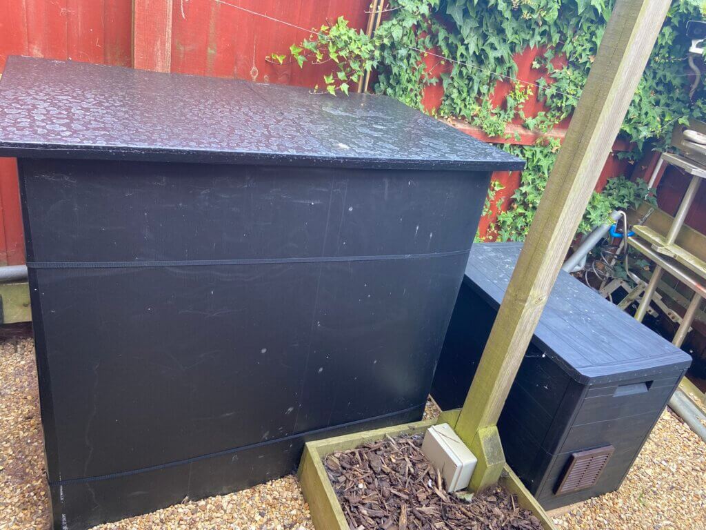
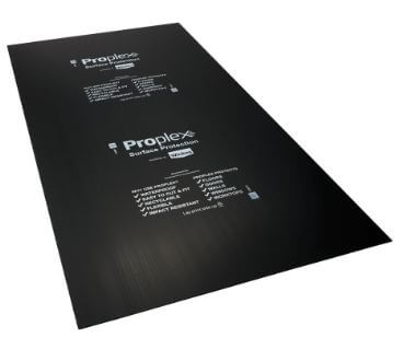
I used 25mm polystyrene sheets to insulate the break-tank and to weatherproof this, I used black opaque floor protective sheets from Wickes which was perfect all held together with Lidl black duct tape:
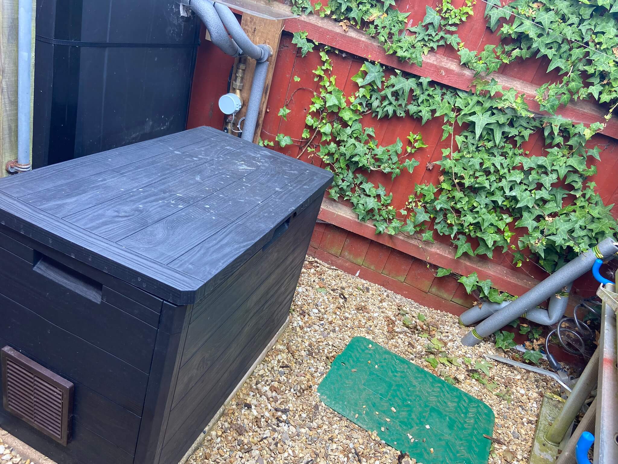
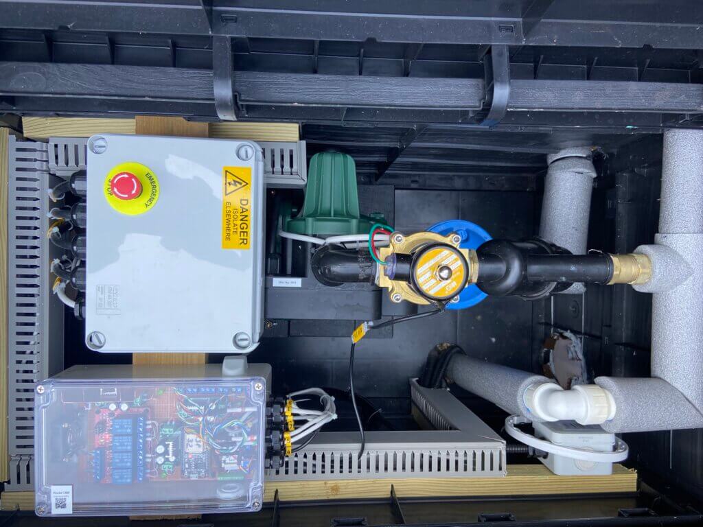
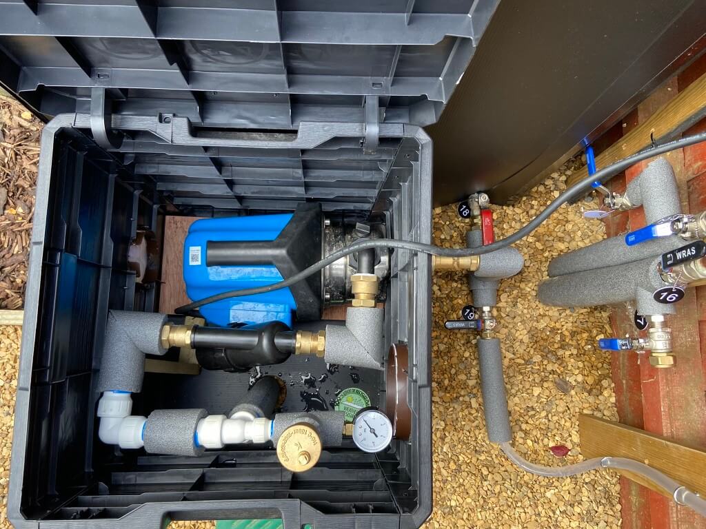
Pump positioned inside an Argos Toolmax 160L Patio and Balcony Chest 326/9408 to keep it out of the elements, ventilation grills and temperature monitoring fitted.
In a ‘Normal’ setup, the pump is connected to a plug via the pump controller and that’s it, however, I wanted to monitor and control certain parts of the system using Home Assistant.
Below is an image of the first iteration of the irrigation pumping system before upgrade:
Sprinklers & Water Usage
The sprinkler assembly comprises of the spray body, sprinkler head and a water inlet, I opted for the Hunter PRS40 body with an assortment of MP Spray Rotator heads to suit my application.
The benefit of using PRS40 body is that it has an inbuilt pressure reducing valve giving me flexibility on the pump pressure, the body limits internally the water pressure to the sprinkler head to 2.75 bar (40psi) which correlates to the sprinkler head data for spray patterns and water usage, this means that as long as the water pressure is greater than 2.75bar to the body along the pipe run and at the furthest point, everything should work as designed.
The spray bodies water inlet is a female 1/2″ BSP, in order to connect to the irrigation main line, I used a Sprial Barb fitting – 1/2″ male elbow (Stock Code SF-SBE-050), two are needed, one on the spray body, the other for the 20mm pipe fitting.
A semi-flexible pipe links the spray body and main feed pipe, this pipe is called Swing or Funny Pipe (no idea why!), the code for this is SP30. Part codes used are from Sprinkler Irrigation.
My system uses 15 sprinklers with MP rotators:
1 x MPSS530 – Side Strip pattern
1 x MP2000 – 900 – 2100 pattern
1 x MP1000 – 2100 – 2700 pattern
12 x MP1000 – 900 – 2100 pattern
Water consumption per sprinkler head is dependent on the adjusted coverage pattern, the rotator data sheet enabled me to work out the expected water volume, data also exists on the Growinsane website regarding emitters l/m, again this is dependent on adjusted flow at the specific emitter.
Total front lawn – design usage 19.2 l/m, measured usage 21 l/m
Rear planters and pots – measured @ 16.6 l/m
The Hunter MP Rotator data I used can be found HERE, however, a revised Metric version is HERE.
The rear garden has a number of the following emitters, the l/m value is for each emitter:
I ‘tweak’ and constantly review the ‘run times’ now I understand how effective the sprinkler head patterns are at delivering the required volume of water to the lawn and plants
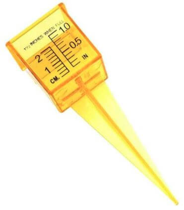
Water gauge from AliExpress – £6.73 for 10.
The volume of water filling the gauge drives the watering run time as I’m looking for an average total of 25mm per week on the lawn, (this is a cumulative total and will include rainfall).
The MP Rotator heads deliver a soft watering pattern to avoid runoff and enable the water to soak in, using water gauges placed at random places across the lawns, the average water collected over a 10 minute cycle was approximately 4mm.
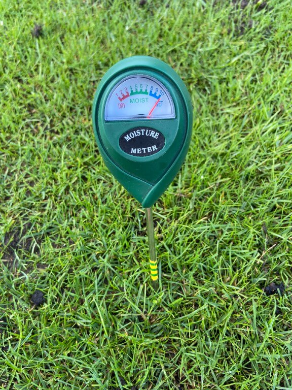
This means that just over an hour of irrigation will give me the weekly total of 25mm, however, I spread the watering periods over early mornings each day as a minimum, if the lawn shows signs of distress, I increase the watering frequency as the whole topic is a ‘black art’ and along as my moisture meter is happy, so am I.
Lawn Watering Cost – Budget for it!!
Updated for 2025Season
The price of 1m3 of water is now £2.68, and I’ve increased my watering cycle to 30 minutes for a deeper watering, using 830 litres each time, adjusting for sewage abatement, the cost per cycle is £2.00.
June has been very warm meaning two cycles per day when its baking hot, costing £28 per week!
Legacy2023 Information
I started a watering schedule in April, this schedule, (duration and frequency), varied based on when I over-seeded and if we have had rain, another consideration was the lack of rain coupled with high temperatures, lots of variables all contributing to evapotranspiration!
The actual cost for running my 15 sprinkler heads for a 117m2 lawn for 10 minutes costs £0.65p per day, this cost is made up of water charges and sewage/foul costs.
To water my lawn for 7 days to give me >25mm costs £4.55 per week.
Where it started to expensive was when it didn’t rain, obvious really :-), Example – June 2023 was a dry, warm month, with only 5mm of rain measured, so with a bit of over-seeding and to keep the rest of the lawn growing, I used 26.8m3 of irrigation water from the 4th June to the 22nd costing £4.54 per day.
The costs used are based on Anglian Water, June 2023 charges, 1m3 (1000 litres) costs £1.68p, add to this the sewage/foul costs which are based on 90% the water used and cost £1.71 per m3.
Update – 2 October 2024
Having taken advantage of the water authorities ‘New Lawn’ allowance before but I didn’t know until a chance conversation that you can request a ‘Sewage Abatement‘ for that does not use the drains, e.g. Irrigation & swimming pools. So instead of a 90% levy, this drops to 10% per 1m3.
I spoke to Anglian Water and they simply record the fact you have called and at the end of the season you let them know how much water you have used on the lawn, I have a sub-meter for my irrigation system, but I double check this against my main meter, once the readings are given to them, they will calculate the rebate.
At the end of the 2023 season I spoke to Anglian Water and my account was credited with £91.66 for irrigation water used, result 🙂
At the end of the 2024 season I spoke to Anglian Water as they still had my usage details, the process was simple and my account was credited with £44.38 for irrigation water used, the two main reasons for the lower cost was I used harvested stored rain water and poor summer.
Update – 24 September 2025
Started irrigating the lawn from the 31st March until 24 September using a total 47m3 of water, Anglian Water abatement refund was £97.01, happy days!
Pipe Sizing
This is probably the most critical element, if any of the pipes are undersized, then the pressure drop at the furthest point may make the system unusable at worst or poor forming at best.
The information I had was, as a rule of thumb, that a 20mm pipe will pass 1000 litres/minute (l/m) and a 25mm pipe will pass 2000 l/m, as I had independent zone control, with the highest water demand zone taking less than 9 l/m, I went with 20mm MDPE pipe as the flow rate, pressure and pipe length all worked out fine for my lawn.
It turns out that the sprinkler head water volume is when the head is at its full design pattern, a number of the heads in my system have had the coverage tailored to my lawn, therefore the water consumption is slightly lower, the DAB Jet 120M allows me to have all 13 sprinklers on at the same time with no adverse effect on water pattern coverage as the pump pressure is healthy.
3 Bar
As stated earlier, the Hunter PRS40 bodies have an integral pressure reducing valve so they operate at their optimal water pressure which is 2.75bar (40psi), it is important therefore, that the pressure reaching the spray body is => than 2.75bar.
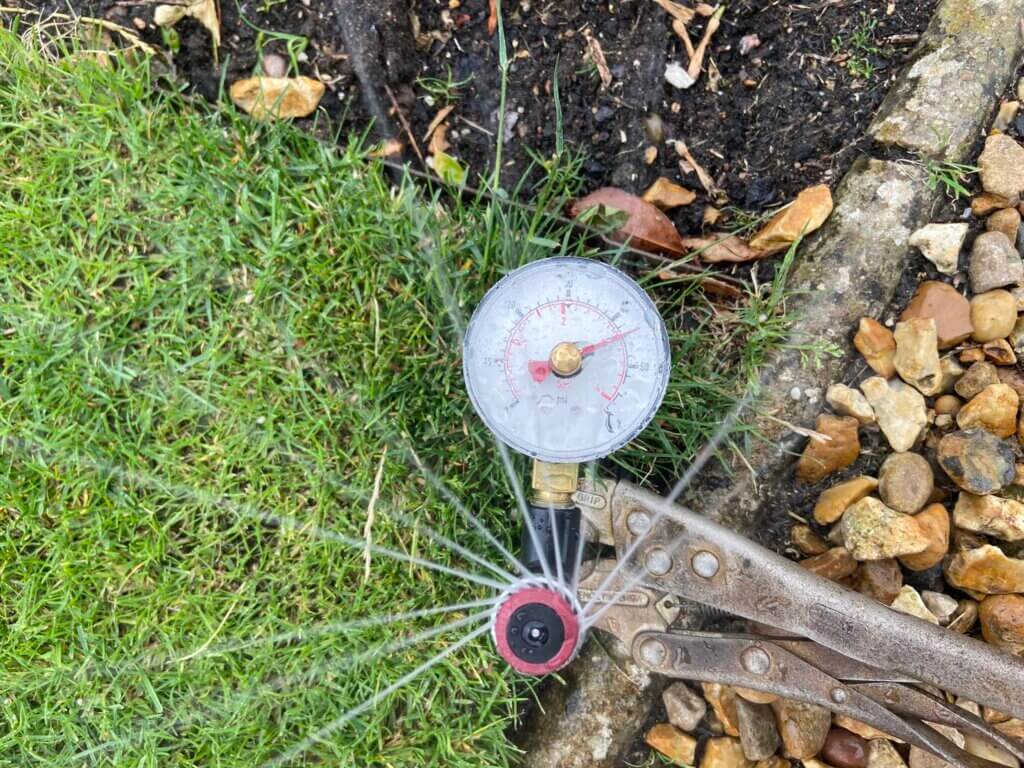
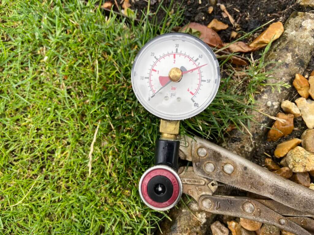
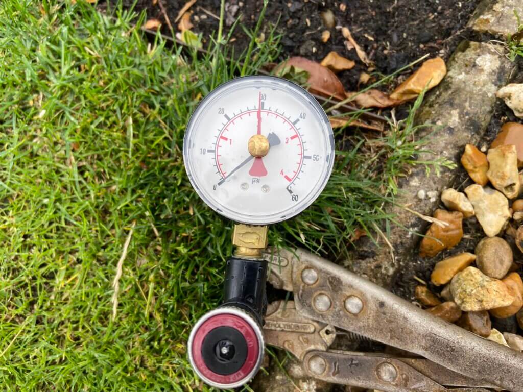
The above reading of 3bar pressure was with all sprinklers working, if I turned on the rear garden watering line as well, the pressure expectedly dropped and recover to 2bar recovered, however, as this is below the optimal sprinkler pressure, I’ll ensure the sprinkler schedule does not have all four zones on at once.
2 Bar
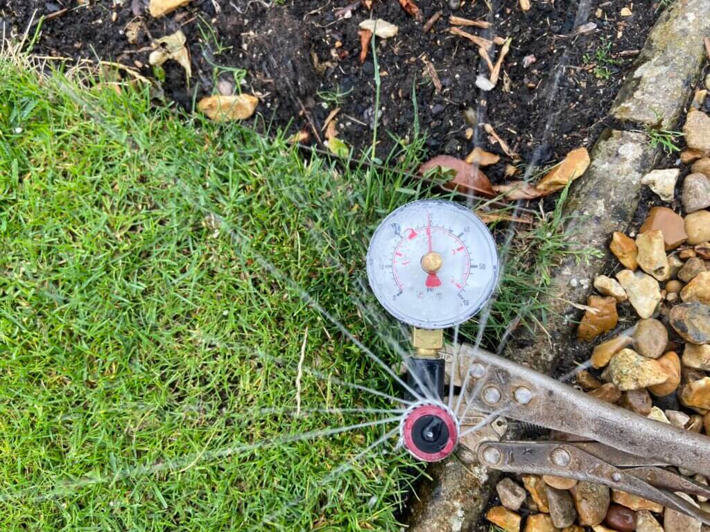
Pressure readings were taken using a MPADAPTER which allowed me to measure the dynamic pressure reaching the furthest sprinkler heads on each zone, determining if => 2.75bar pressure is being achieved, which it was :-).
The majority of pipe fittings were from waterirrigation, MDPE pipe 20mm compression fittings require pipe liners (inserts), to stop any deformation of the pipe in the fitting, I was told it was ok to omit this, but as the liner are cheap, I didn’t think it was worth the risk of a leaking joint at some point in time.
Getting a clean, square cut on MDPE pipe is important as it gives a good face for the liners lip to sit against and also it makes insertion past the fittings ‘O’ ring easier with a reduced chance of seal damage, to get a clean cut I used pipe shears from Lidl for £9.99.
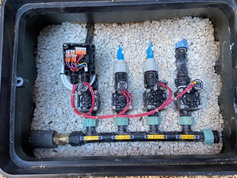
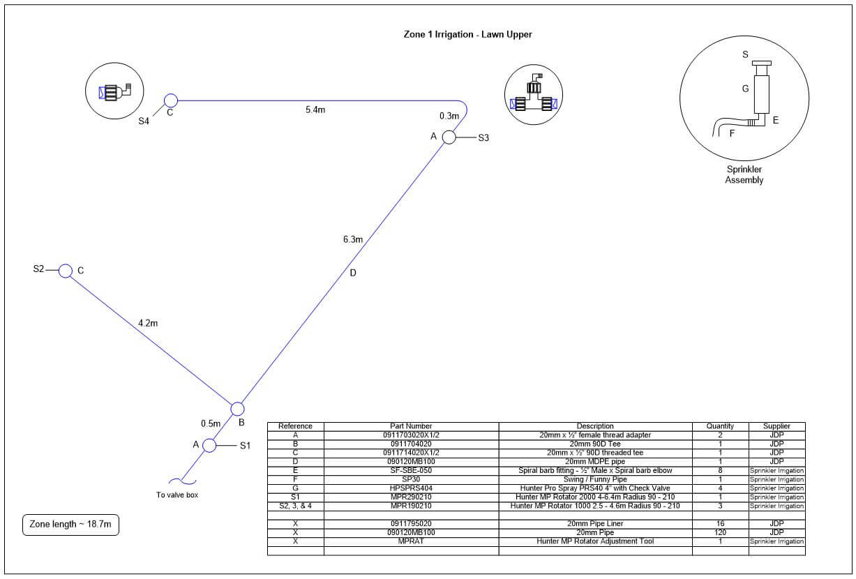
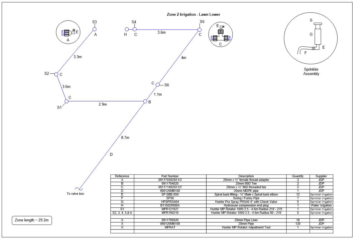
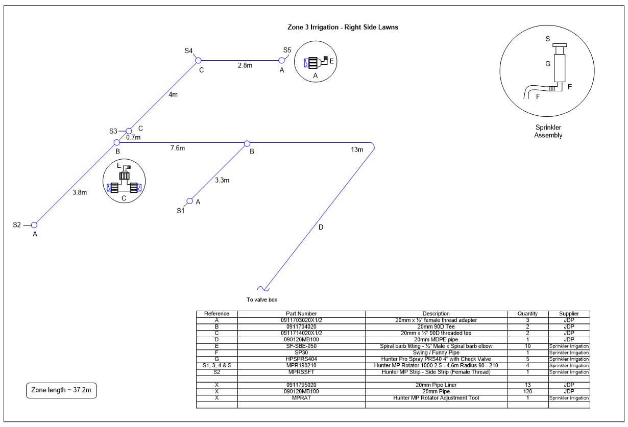
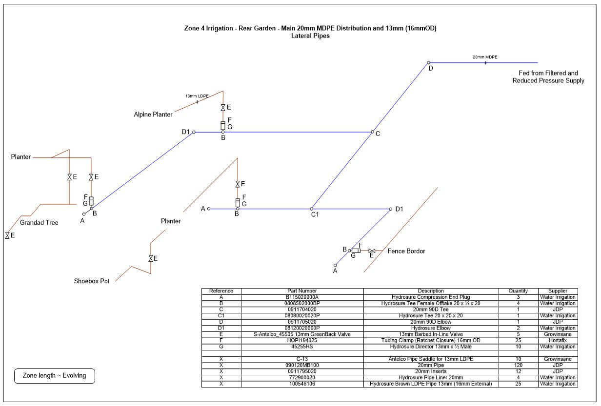
For the greatest flexibility and water consumption distribution, I decided on 4 zones, (from left to right in the valve box):
Zone 1 – Left Lawn Upper (4.82 l/m)
Zone 2 – Left Lawn Lower (8.76 l/m)
Zone 3 – Right & Centre Lawns (5.65 l/m)
Zone 4 – Line/Drip Irrigation (1.75bar pressure reducer fitted)
123456
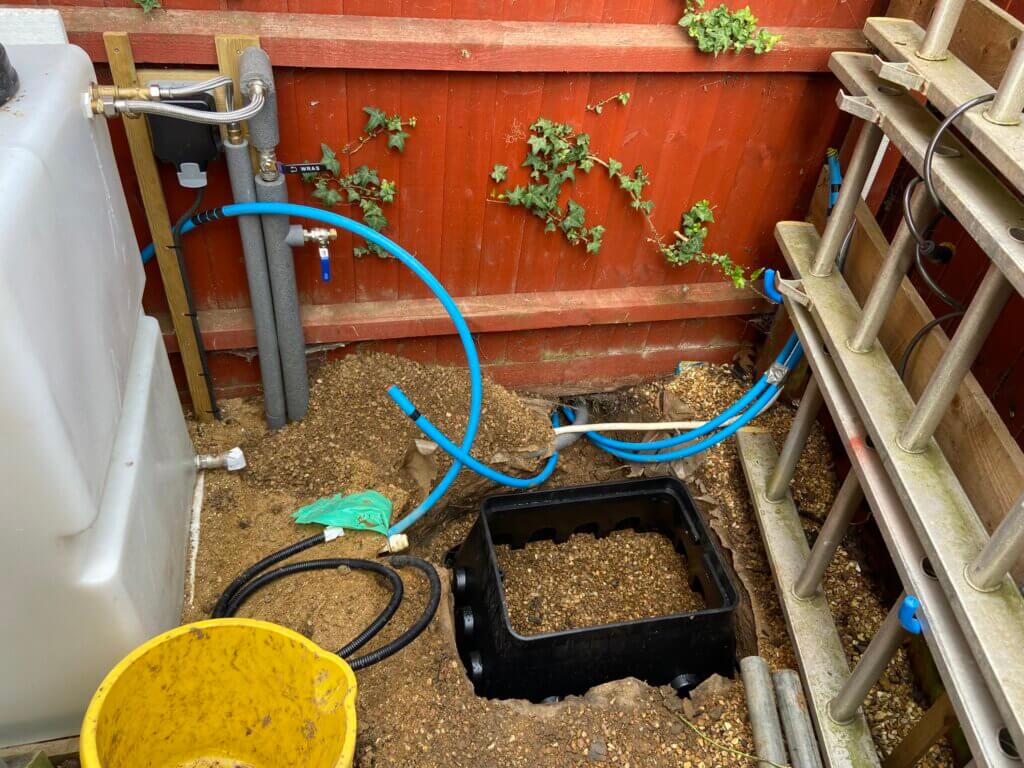
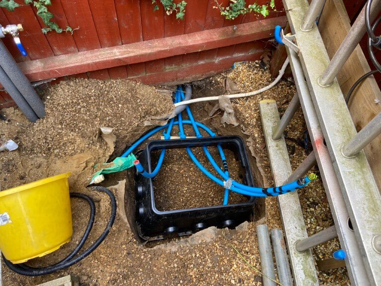
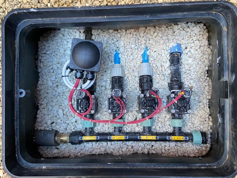
The valve box roughly laid out to ensure ease of working on and that it left room for the pump enclosure.
Irrigation lines roughed in and trimmed, also the correct depth dug to accommodate the valve box ensuring that the lid would be at the correct height above the ground.
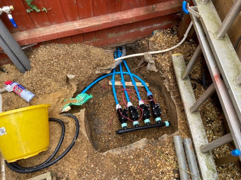
I used a wooden baton with pipe clips spaced at the valve outlet centers to keep the irrigation lines in the correct position without causing any strain on the valves.
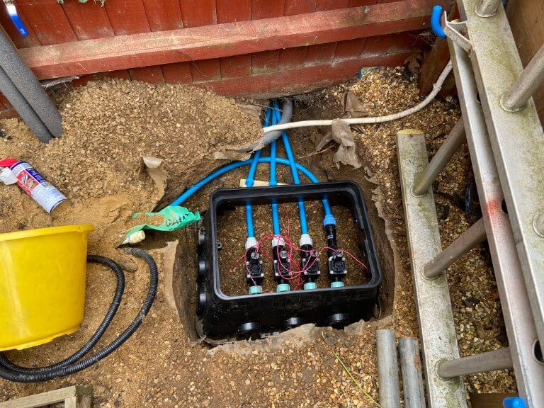
After the pipe were connected to the valves and the valves to the manifold, the valve box body was notched to accept the pipes and then placed over the completed assembly, rather than work with the box in place.
Valve box all levelled and backfilled with pea gravel, decorative white stone is inside the box as I think it looks good, a 25mm conduit was ran from the controller to the valve, through this passes a 5 core 1.0mm2 cable, one core for each valve solenoid and a common return. All connections were made in an Wiska-Combi 308 IP66 rated enclosure filled with Magic-Gel after termination.
All tested and ready for closing up.
Control
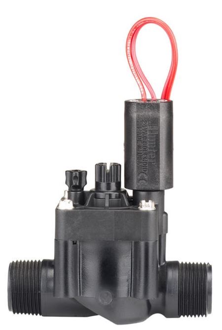
Water to each irrigation zone is via Hunter PGV solenoid operated valves, these need 24vAC to operate, applying 24v will open the valve, with no voltage present, the valve will be in the closed state.
1″ valve, Male threads, part number – HPGV1FCM ELECTRICAL SPECIFICATIONS 606800 • Minimum opening/operating voltage: 19 VAC • Maximum recommended voltage: 28 VAC • Current at 24 VAC: • 370 mA inrush, 210 mA holding, 50 Hz • Maximum operating pressure: 15.17 bar; 1517 kPa • Wire leads: 45 cm of 0.8 mm2 UL-approved wire
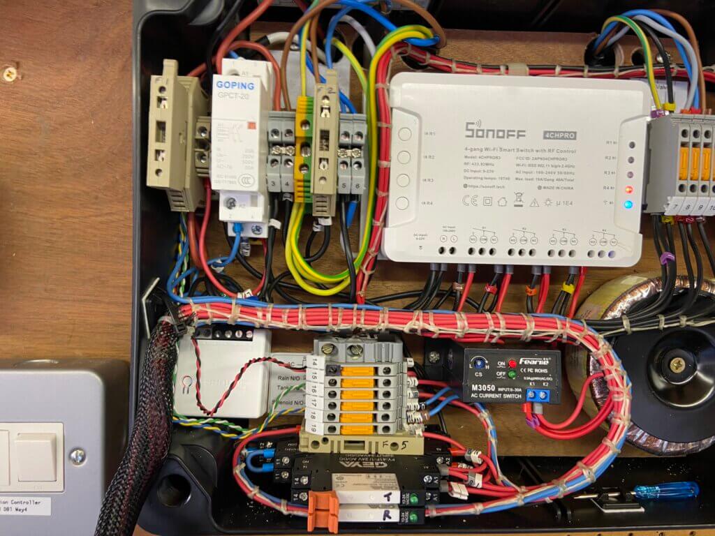
Hunter do make controllers for their range of valves but I decide to make my own using a 4 channel Sonoff Pro2 as the valve controller and a Sonoff Basic as the pump control configured as a ‘scene’.
Version 3
The Sonoff devices are paired to home WiFi and operated through the eWeLink App or dashboard, these are extremely flexible devices and ‘scenes’ can be setup, so that the actions of one device can effect the operation of another.
The channels of the 4 channel Sonoff controls the solenoid of that valve, initially I had the Sonoff set to ‘interlock’ mode, meaning that only one of the 4 channel relays can ever be ON, but once I was able to test the pumps pressure and monitor the sprinklers performance, I decided to remove the interlock enabling greater flexibility of operation.
Sonoff Scene
As this is a new system, I’m working through the best watering times, the ‘scene’ I have currently set, (a ‘scene’ is a pre configured set of events that automatically run when triggered), at 04:00 on Monday, Wednesday and Friday , valves 1 and 2 open for 40 minutes, then valves 1 and 2 close, then valve 3 opens for a further 40 minutes, valve 3 closes and valve 4 opens for a further 5 minutes.
At the end of the 5 minutes, valve 4 closes and the pump turns off.
Before going live with a scene configuration, I use a test rig to confirm operation of a scene before making it live.
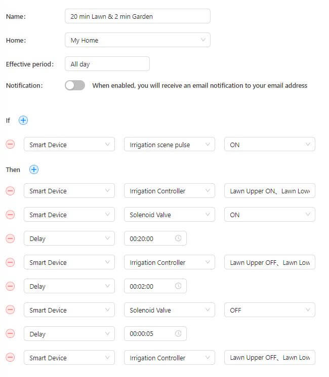
The scene below is to manually operate the watering schedule and can be easily ‘tweaked’ using the eWeLink dashboard:
The scene breakdown is as follows –
The irrigation sequence is triggered by manually operating the app.
1st action is for the Sonoff 4Ch Pro relays 1, 2 & 3 to turn ON, this in turn supplies 24vAC to OPEN the control valve solenoids to the front lawns.
2nd action is for the Sonoff Basic Smart Device to turn ON and supply power to the solenoid via a contactor, this causes water pressure to drop and the pump automatically starts.
3rd action is the Delay of 20 minutes, this is the period of time to elapse before the next action i.e. the valves are ON until the next action
4th action, at the end of the 20 minute delay time, Sonoff 4Ch Pro relays 1, 2 & 3 turn OFF and relay 4 turns ON to water the rear garden.
5th action is the 2 minute duration that water will pass through valve 3
6th action is that after the 2 minute delay time above, Sonoff Basic turns OFF and the solenoid valve closes.
7th action is a 5 second delay time before the Sonoff 4Ch Pro turns relay 4 OFF.
With all valves closed the pump will stop once a pressure of 1.5bar is reached.
I found quite early on that it was important to set up a ‘scene’ to turn OFF the Irrigation Controller relays and Pump as, in my case, access to physically operate Sonoff devices is not possible as they are within an enclosure.
A 230v/24v – (3.75A Max Output) Toroidal transformer is used to supply the operating voltage to the Hunter valves via the 4 channel Sonoff.
Version 3
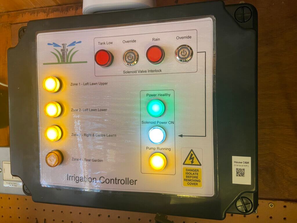
Panel shows the irrigation system cycle is running, if the feed water tank is low or if the rain sensor has activated, this will disable the solenoid contactor and the cycle will abort, operating the respective override buttons enables continued running should it be required.
Front panel label, LED lights are from AliExpress, the ‘Pump Running’ LED is switched via a AC current sensing relay with the light only being illuminated when a pre-configured load is being drawn. This gives confidence that the pump is actually consuming power and running, rather than simply powered up.
To make the panel overlay I use Visio to make the image to scale and print to A4 80gm paper, this is then covered in a self-adhesive transparent book covering affixed to the enclosure with double sided tape.
Home Assistant and Interlocks
I’m not a programmer, so I can only use what I know, this ends up a bit ‘clunky’ but it works for me.
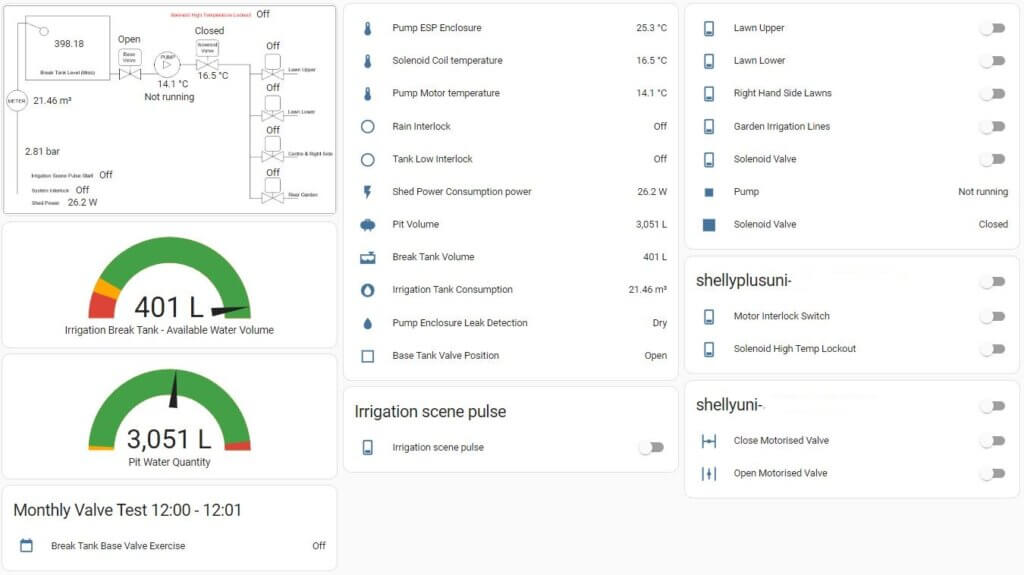
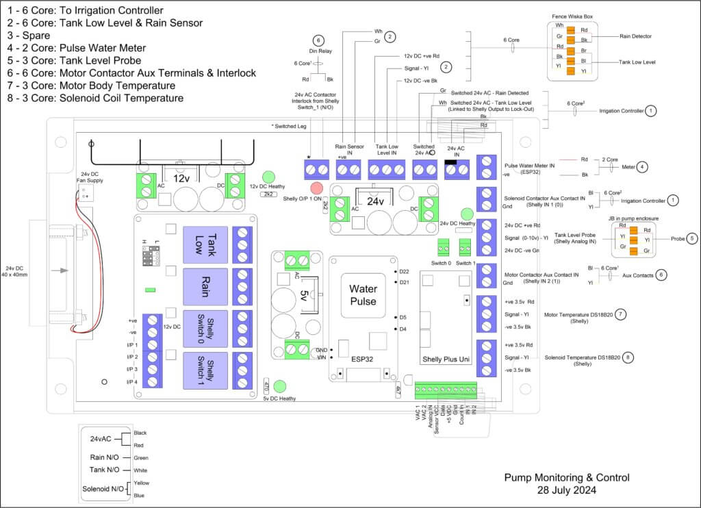
I use Home Assistant to monitor the Break-Tank water level using a submersible hydrostatic sensor from Aliexpress wired to a Shelly Uni Plus, the Shelly also has two temperature sensors attached, one for the motor casing and the other to record the solenoid coil temperature.
The Shelly Uni Plus is very versatile as it also has two controllable outputs, one of these is to manually open the circuit to the motor contactor, effectively an emergency stop and the other output is linked to the solenoid temperature exceeding 500 C, if it does then the solenoid contactor circuit will open removing power from the coil.
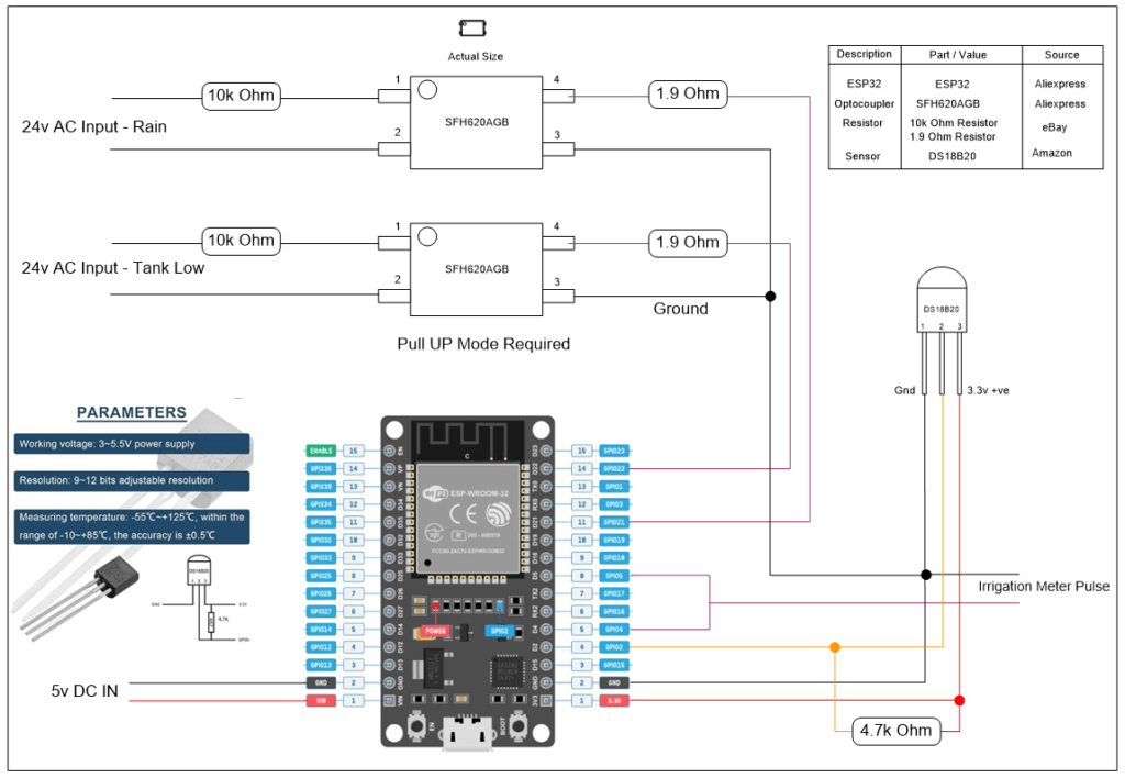
A ESP32 is used to measure the water meter pulses giving me a reading of water volume in m3 used to fill the Break-Tank, I also monitor the internal temperature of the enclosure and the status of the Break-Tank low level sensor and external rain sensor with the ESP32.
This was the most difficult part of the whole project as I did not have an understanding of the parts, only an idea of what I wanted, fortunately the cost of parts is quite inexpensive, so if I bought the wrong thing it wasn’t so much of a big deal.
The rear garden system starts at the water control valve, the pump pressure of 4 bar is too high and must be reduced, I used a Hydrosure 1.75 bar pressure regulator connected to the 1″ control valve outlet with a 1″ BSP female to 3/4″ BSP female reducing socket, the pressure reducer has a throughput of between 0.4 – 30 lpm.
The reduced pressure irrigation water was fed to the garden via 20mm MDPE pipe, with branches made using Hydrosure compression Tee fittings with 1/2″ female offtakes.
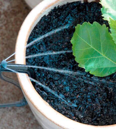
Into the 1/2″ female offtake a Hydrosure Director 13mm x 1/2″ BSP male is screwed in, and from this 13mm LDPE pipe is connected, this is the line into which the micro irrigation parts are pushed into.
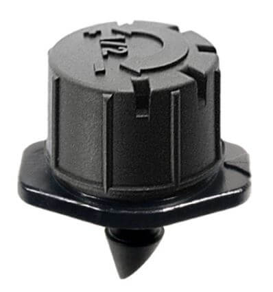
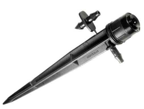
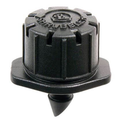
At each planter or main branch I fitted inline isolation valves, sprinkler emitters and shubblers simply push into the thin walled brown LDPE pipe, the use a key punch to make the holes is recommended.
To the left of the picture you can see one of 20 Potstream emitters connected to the main line with 6mm OD x 4mm ID micro PVC pipe.
Pipes can be buried and spray heads are very discrete.
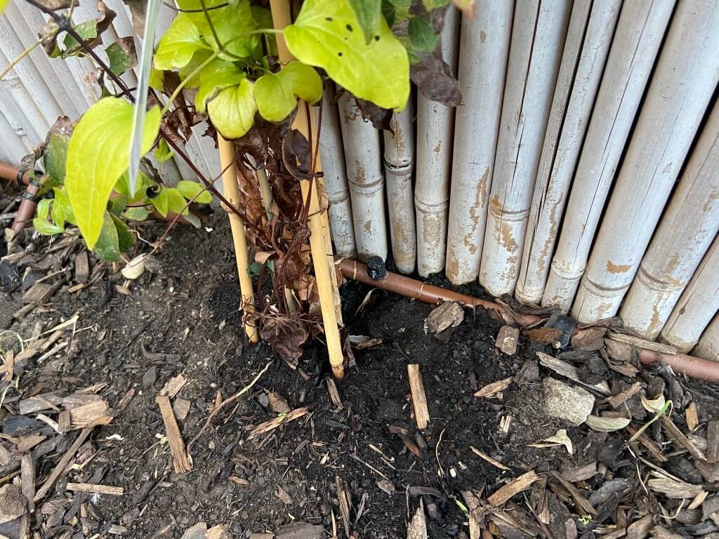
Picture shows a Shubbler 180 emitter connected directly into the LDPE pipe, unfortunately the clematis is struggling as the dog thinks its a lamppost.
The micro irrigation emitters do not come with water usage data, I estimate that my system uses 27 litres per minute (lpm), this is just below the pressure regulators maximum throughput of 30 lpm.
Winterisation
The system will be drained during the winter months to avoid any issues with freezing, hence I was happy with the pipes buried depth and also the lack of below ground lagging.
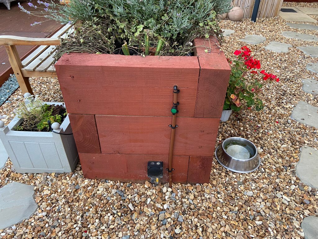
I have adjusted the original installation to include a fence mounted bib tap so I can benefit from the pumps pressure when watering the lawn, plus the water is separately metered, so I can claim back the sewage abetment payment, the byproduct of this is a connection point to blow all the water lines out.
Although the break-tank will be empty over winter, I decided to insulate the tank when I was boxing the tank in.
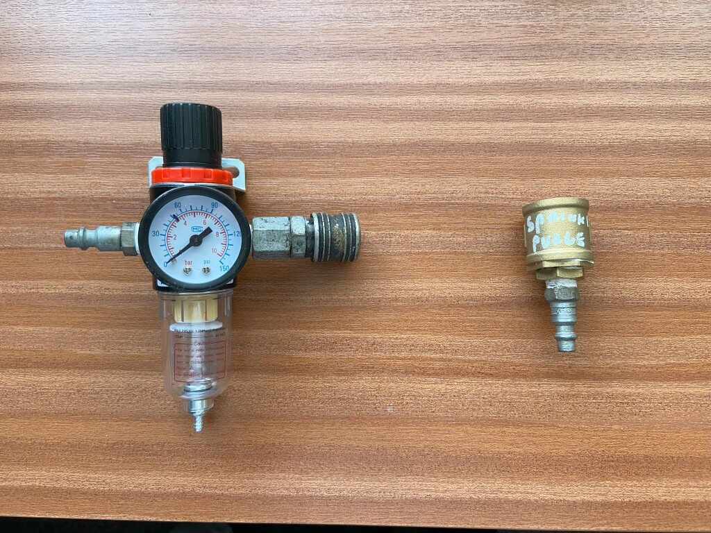
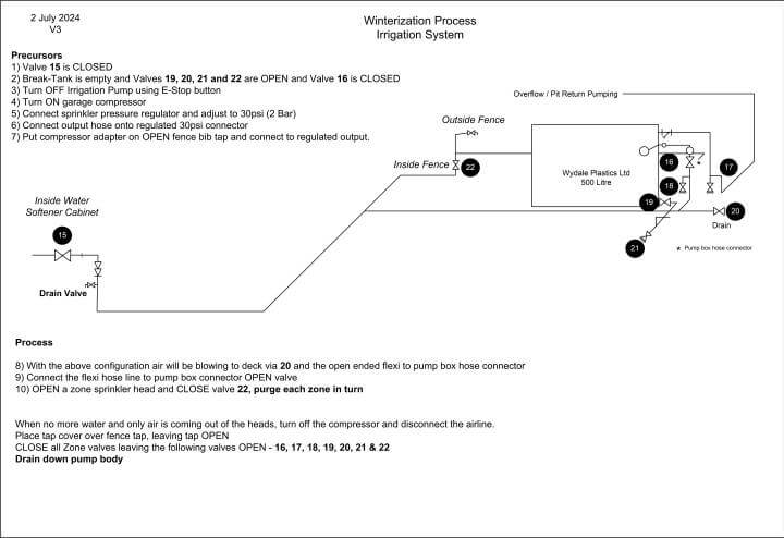
I already had a compressor (15CFM), so the parts needed to blow the system out were fairly inexpensive, these being a pressure regulator and adapter for the outside tap where the compressed air will connect to.
The regulator was £9.95 from eBay, the tap and adapter parts are listed below (Screwfix):
Bib Cock outside tap -590FA
3/4″ Female Socket – 52588
3/4″ to 1/2″ Bush – 98427
1/2″ to 1/4″ Bush – 79207
1/4″ Male Adapter Airline – 2015H
With the above, I connect the regulator, set to 2 Bar (30 psi) to the compressor with the regulated output , via an airline to the tap adapter on the outside tap, this worked really well for me.
2023, Thank you to everybody who has found this blog useful, got in touch or commented, I’ve tried to keep this blog up to date with things I’ve done to the system as you can always ‘tweak’ the system and continue to play with it, especially after the hard graft of fitting it.
Watering the lawn and tailoring it when and how long is now a simply press of a button and I would defiantly recommend investing the effort as the payback is more time for other things, year on year.
The system required very little maintenance, blowing the lines out for winter was straightforward, I did however, waste water by leaving the winterisation process a bit to late, meaning instead of using the water in the tank for the lawn, it went to drain as I didn’t want the risk of freezing damage to my tank, even though its insulated.
Bringing the system back online for a new season was very easy and non of the sprinklers malfunctioned or got stuck in the retracted position.
The main additions to my system since I initially blogged it are:
Dedicated bib tap for my garden hose fed directly off the irrigation pump, this gives me a higher pressure than the mains for washing down or using an impact sprinkler should I need to.
Tip – Know when your going to use the sprinklers for the last time, isolate the filling water to the break tank in order to leave it empty over winter.
Tip -Unplug the pump at the same time as draining down just in case it gets activated by accident and is damaged by running dry.
Tip – A number of my sprinkler body’s had moved from the vertical or sunken since installation due to the ground settling requiring the spade to come out for readjustment.
I have now hammered in a supporting pin parallel to the sprinkler and fastened with cable ties the body to the pin in a hope that this will keep things level.
Tip – One of the jobs on the lawn is to aerate and I really struggled finding the sprinkler heads without turning on the system, so I bought a pack of Survey Flags from Amazon and marked where they are and the buried pipe runs, so I know where I have to either avoid or go easy when plunging sharp tines in the ground 🙂 .
After deciding on a permanent irrigation system and researching options, two brands were of serious consideration, Hunter and Rainbird, both excellent, however, it was ease of access to documentation, product range and product performance which made me decide on Hunter, specifically the rotating spray head patterns.
Where are you going to get the water from is the starting point, if you have good water pressure and flow (by measuring it), it may be possible to drive the irrigation system directly from the tap, if so you have saved a lot of money.
If you have poor water pressure, then you will need somewhere to store the water, (unless you have a well or watercourse), and a pump, as you cannot connect a pump directly to a tap.
This is the daunting bit, but it is something you can do, I used the Hunter Design Guide, which is full of useful information and the steps to follow.
I tend to overthink everything and you could throw in a few heads, linked with hose pipe connected to a tap and it might work perfectly, I on the other hand need to work everything out before I commit to effort and spending money.
Find your water pressure and flow rate.
Make a scaled drawing of the area you need to irrigate.
Look at manufactures literature and determine the appropriate head pattern and number needed to give overlapping coverage.
Total up the water consumption of the heads or the water consumption per zone if you logically can section your lawn.
Draw in pipes runs and work out pipe lengths.
Using the calculators in the FAQs or online determine pipe and pump size (if needed).
With the above info you will now know how much water you need and if you can supply that from a tap, if you can't, consider water storage and how quickly the storage tank will refill as this will be the limiting factor for how long you can water for at a given flow rate.
I've not touched on how the irrigation system will controlled as I made my own, however, these are readily available and simply send a 24v signal to a solenoid water valve to open or close at predetermining time and sequence of your choosing, some are linked to a mobile app for even more flexibility.
Pumps need to push a volume of water (output) at pressure, these are measured in Litres per minute (L/m) and Head respectively.
The pump used in this blog for example has an output of 61 l/min, so theoretically I can supply 19 x MP1000 360 degree rotator heads, with each using 3.18l/min at the same time, obviously this does not take into account sprinkler pipe and fittings friction losses.
Head relates to the pumps pressure and mine is 46 meters (46m), the easy way to roughly convert this to bar, (a bar is 14.7psi at sea level), is to put a decimal point in-between the number, so 46m, becomes 4.6bar.
Handy converter for Head pressure is HERE, (SG - Specific Gravity of water is 0)
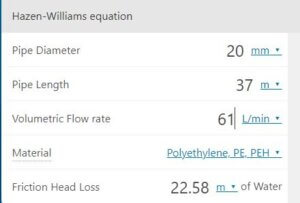
Earlier I mentioned pipe friction losses, to put this in perspective my longest run is 37m of 20mm pipe and my pump pressure is 4.6bar, if I had 19 heads taking a total of 61 l/m then the pipe losses would reduce the pressure at the end of the pipe to 2.35bar, well below the pressure required for the heads to operate effectively.
Residential irrigation controller use 24vAC outputs to power water valves, whereas pumps need 230vAC.
If the controller you choose has a 24vAC output to switch a pump on, you will need a relay to switch the higher voltage and current, these are about £6 on eBay, search for AC24V Coil 8 Pin DIN Rail Electromagnetic Power Relay 10A w Base.
If the controller doesn't have a pump auxiliary output then you can use an automatic pressure switch, such as the Smart Press.
What this does is monitor the pressure from the pump, if the pressure drops, such as when the watering valves open, the pump automatically turns on and will continue to run until the watering valve/s close, also this device stops the pump if it runs out of water to protect the pump.
No, these are bought separately due to the extensive range of spray pattern types, the heads simply screw into the PRS40 body, the other bit you will need is a connection elbow to the base of the body.
From the solenoid valves to the sprinklers, I used 20mm blue poly MDPE pipe with inserts, the final connection from the poly pipe to the sprinkler body is with 1/2" flexible hose.
20mm was fine for my setup as its based on how much water it will pass in litres per minute over the total length of pipe at the correct pressure, the longer the pipe, the more pressure is dropped, hence sometimes its easier to go up to 25mm if your not sure.
This relates to how high the sprinkler 'pops up' out of the ground, either 4" or 6", the range of the water pattern is greater the higher up it is, but this is based on the design, I manage fine with a 4" lift.
The main consideration was how long was my aerators tines as I didn't want to damage the pipes at a later date, I buried mine 200mm (8") down which is the length of the trenching shovel I used.
The pipes are blown empty over winter so I have discounted any freezing risk.
Since installing my system, I did see a guy on YouTube who used a reciprocal saw to cut this trench and it worked really well as a great idea as long as you are sure you have no buried services.
The cost for my system was under £900, but I made mistakes, so this blog should save you money in unnecessary purchases, the installation was hard physical work but incredibly rewarding when finished.
The main benefit is that I can sit back and the lawn will be watered to a consistent standard, every time, allowing me to do other things, like sleep 🙂
For me it was the line irrigation to planters and drip feeders, the terminology is difficult to understand so I ended up buying lots of things which are now sat in a box, fortunately the bits are relatively inexpensive.
8 June 2022 – Netomnia press release regarding full fibre broadband to Doddington – details HERE, (doesn’t mention Chatteris, but in the current infrastructure works permission from Cambridgeshire County Council, Netomnia have used the Project Reference as – J032025-172553-Doddington).
Letter from Netomnia
Dated 13th June 2022, addressed simply to ‘The Occupier’, warming people up to minor disruption due to civil works, with the end advantage of FTTP Ultrafast broadband.
I was informed on the 28th June 2022, that the Youfibre website was allowing certain Chatteris postcode areas to pre-order the service, this early tranche looks that the selected properties have connectivity to the buried Openreach duct system, those properties with overhead or directly buried cabling are not included as yet.
I used Postcode Checker to determine service eligibility at the moment.
If you want to ‘dip your toe’ in the Youfibre pool, you can sign up for a ‘no contract’ service, instead opting for a 30 day rolling renewal option.
1 July 2022 – For Info: Direct Debit set up with my bank using the name of “GC re Youfibre Limited”, the GC stands for GoCardless the company they use for Direct Debit collections.
30 June 2022, I’ve pre-ordered 150Mb service and received my confirmation, the key points are:
Pre-order early and get 6 months free
150Mb package costs £25 inc VAT for 18 month contract
As its a pre-order, no monies are taken until service is delivered
As this is a pre-order, I can cancel my intention for installation without penalty
I can take up this offer, at this set price for up to 24 months into the future, this will allow time for my existing service contract to expire and it will also allow me to let people know of my gmail email address, rather than the one tied into Talktalk.
19 June 2022 – Youfibre ‘door to door’ canvasser called, informing me that Youfibre is coming to the area and was looking to see if I was interested so that I could receive a’ follow up call’ and newsletter, I did say I was already signed up, but I think she needed my details for her ‘quota’.
20 February 2023 – I decided to renew with TalkTalk for a few reasons:
Uncertain that Youfibre will be live when my current TalkTalk contract expires, meaning the loss of any bargaining power,
TalkTalk offered 150Mb service for £23 per month on an 18 month contract, which is cheaper than I was paying for 65Mb,
I reflected on how I felt ‘locked in’ to the TalkTalk email service, for example the number of accounts where my password resets link to this,
My home network would need a static IP from Youfibre at an additional cost of £5 per month making the overall cost unattractive,
Youfibre in the town helped me negotiate a competitive price from TalkTalk.
23 February 2023 – Netomnia network is now live to certain parts of Chatteris as the roll out continues.
FTTP Rollout
Yet more choice for broadband provision in Chatteris, with the rollout of XGS-PON. 100% fibre to the premises, (FTTP) supplied by wholesaler Netomnia, whose mission is to become the third largest national, full fibre infrastructure operator.
The main difference with Netomnia is that it is a totally independent network, synchronous or symmetrical speeds, (same uploading speed as the downloading speed), resilient fibre optic design and with speeds up to 10Gbps(10,000Mbps)!!.
Netomnia sister company, YouFibre, are the Internet Service Provider (ISP) for this Ultra Fast Broadband FTTP, although it is expected that other ISPs may take advantage of the services that this wholesaler offers and partner with Netomnia.
Unforeseen Delay to Delivery
The expected go live date was September/October 2022 and availability and rollout details can be checked HERE, this has been delayed due to unforeseen duct blockages or lack of duct capacity necessitating significant civil works.
PartialGo live for Chatteris is February 2023 as I understand it.
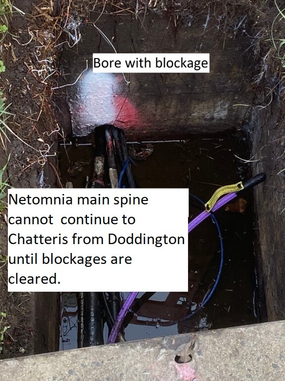
The Openreach duct route from Doddington has been extensively damaged over time due to it being made of clay, this has led to investment in repairs and new ducting to be installed.
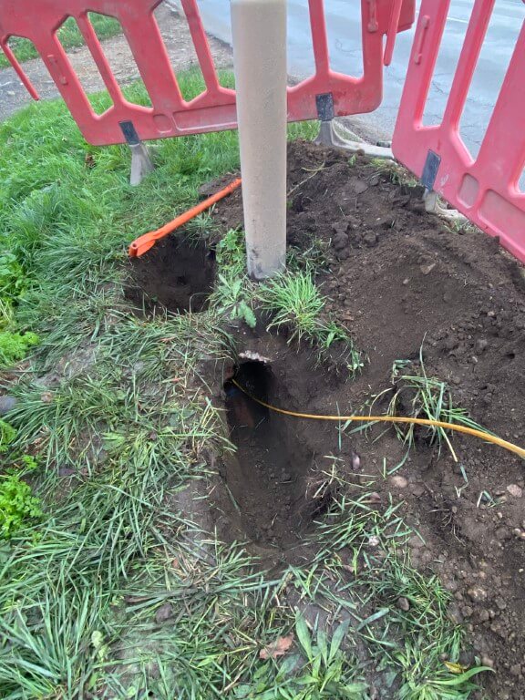
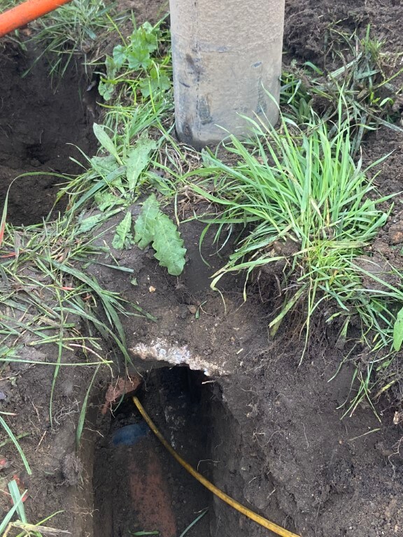
The above images are just one example of what Netomnia are up against, the installer of the street lights in a section of Doddington Road have damaged and blocked the clay Openreach ducts, meaning that the main spine fibre cannot continue to Chatteris until repaired (Taken 1/12/22).
Infrastructure Enabling Works
Flurry of broadband activity in the town, as Virgin Media are expanding their existing infrastructure at the same time as Netomnia are installing theirs.
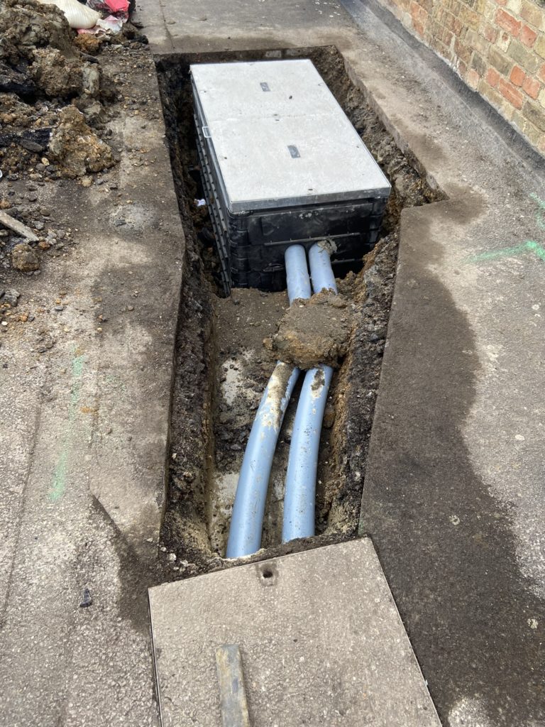
Netomnia infrastructure works started in early May, with the installation of Netomnia double size footway boxes to house either the Level 1 (L1), Level 2 (L2) or both splice enclosures for there dedicated fibre network around the town.
These will be interconnected by sub ducts which will ultimately connect to the main spine bringing the fibre service into Chatteris via Doddington.
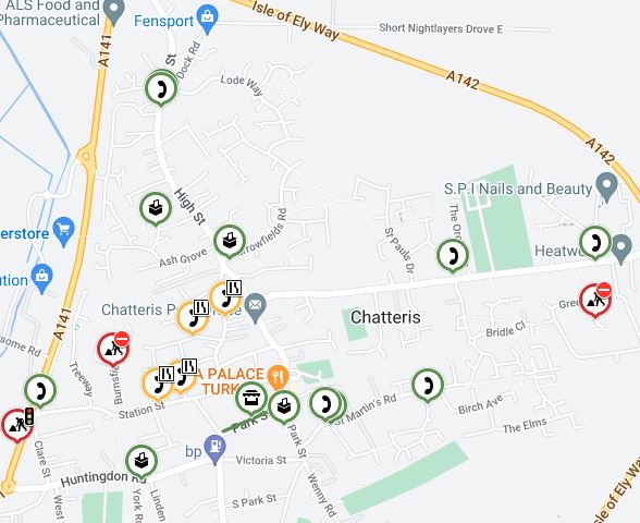
Details from – https://one.network. The telephone handset symbol shows areas of of work by both Virgin Media (Orange circle) and Netomnia (Green circle) contractors for 26th to 30th May 2022
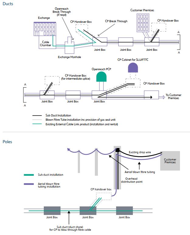
The fibre sub ducts are being drawn into Openreach’s existing ducts as a result of OFGEMS Physical Infrastructure Access agreement which permits Communication Providers access, this means there is not a lot to see as the splicing nodes will be in the cable chambers in the pavements as I understand it.
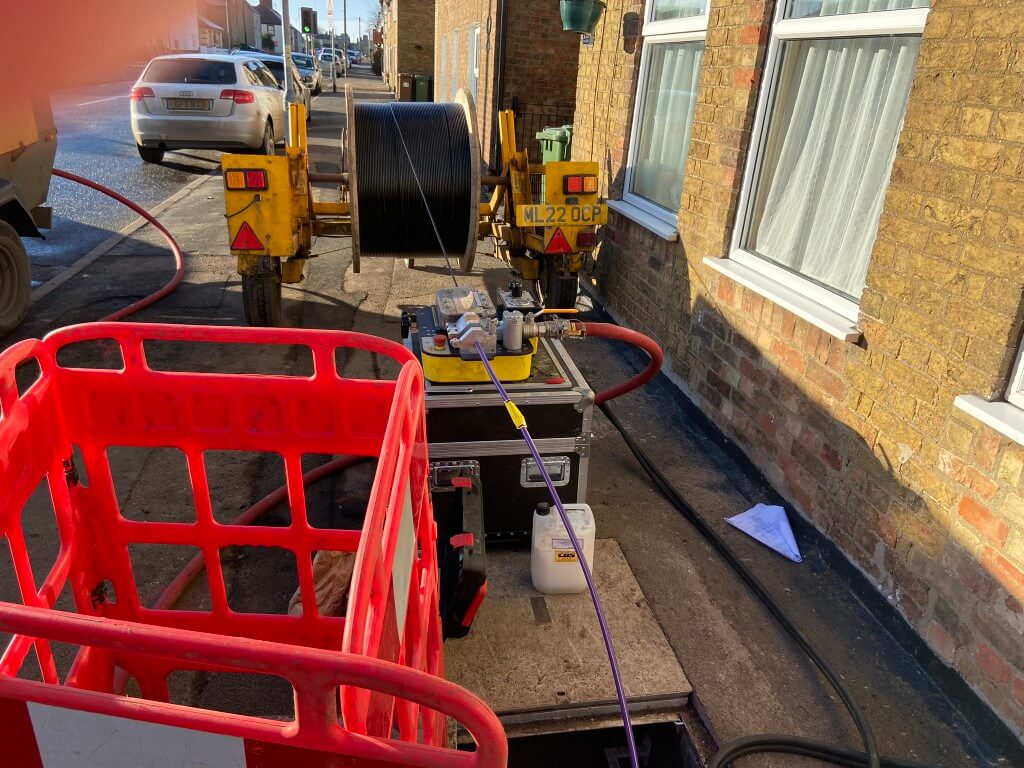
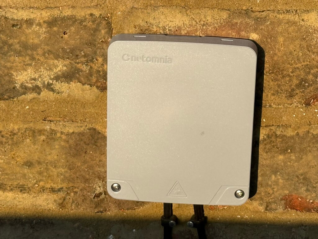
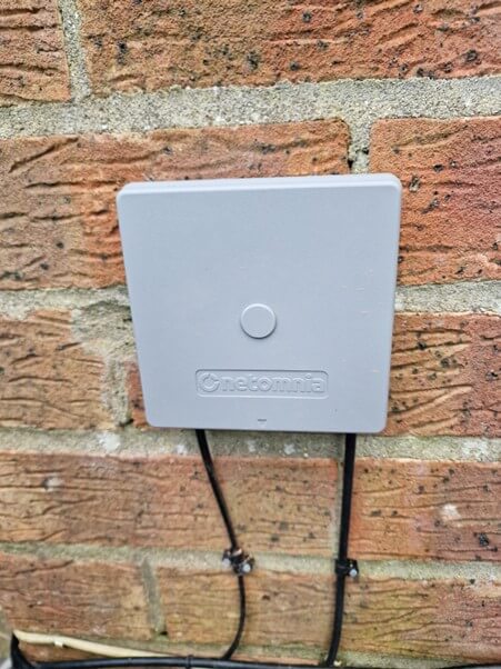
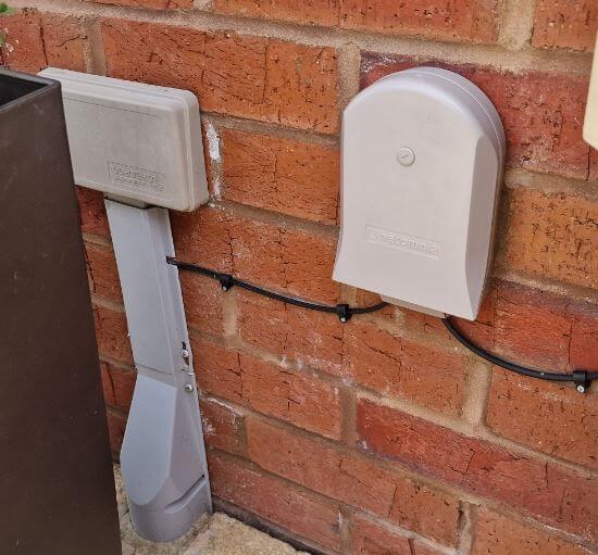
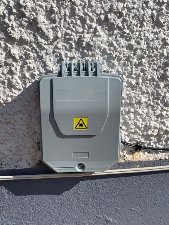
By using Openreach ducts, just like Virgin Media are doing, the micro duct which brings the blown fibre to your house, uses the existing duct which is used for your landline telephone. If the service is via an overhead line, a fibre cable can also be used, Netomnia have, in other towns, installed telephone poles where otherwise customers would not have been able to get a service.
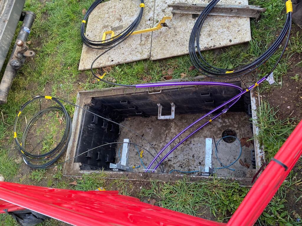
The ducts Virgin Media use are Green in colour, whereas Netomnias ducts are Purple and Openreach are Grey, all for ease of identification.
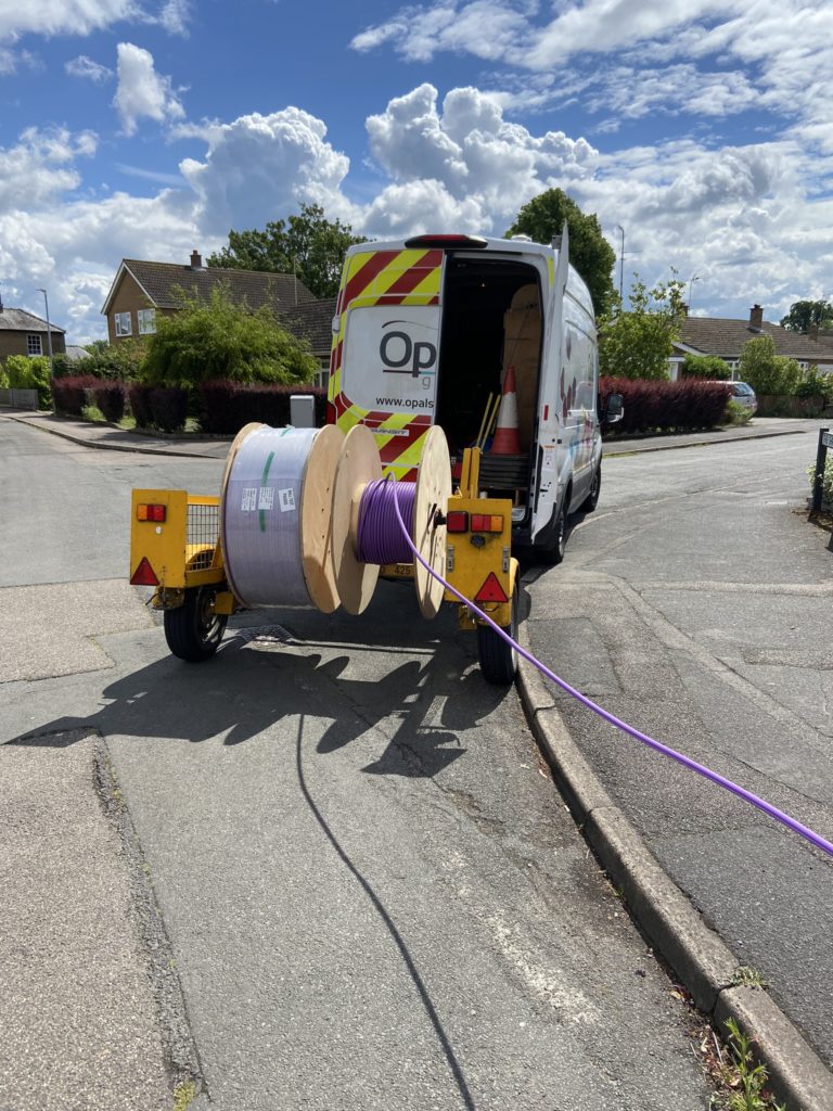
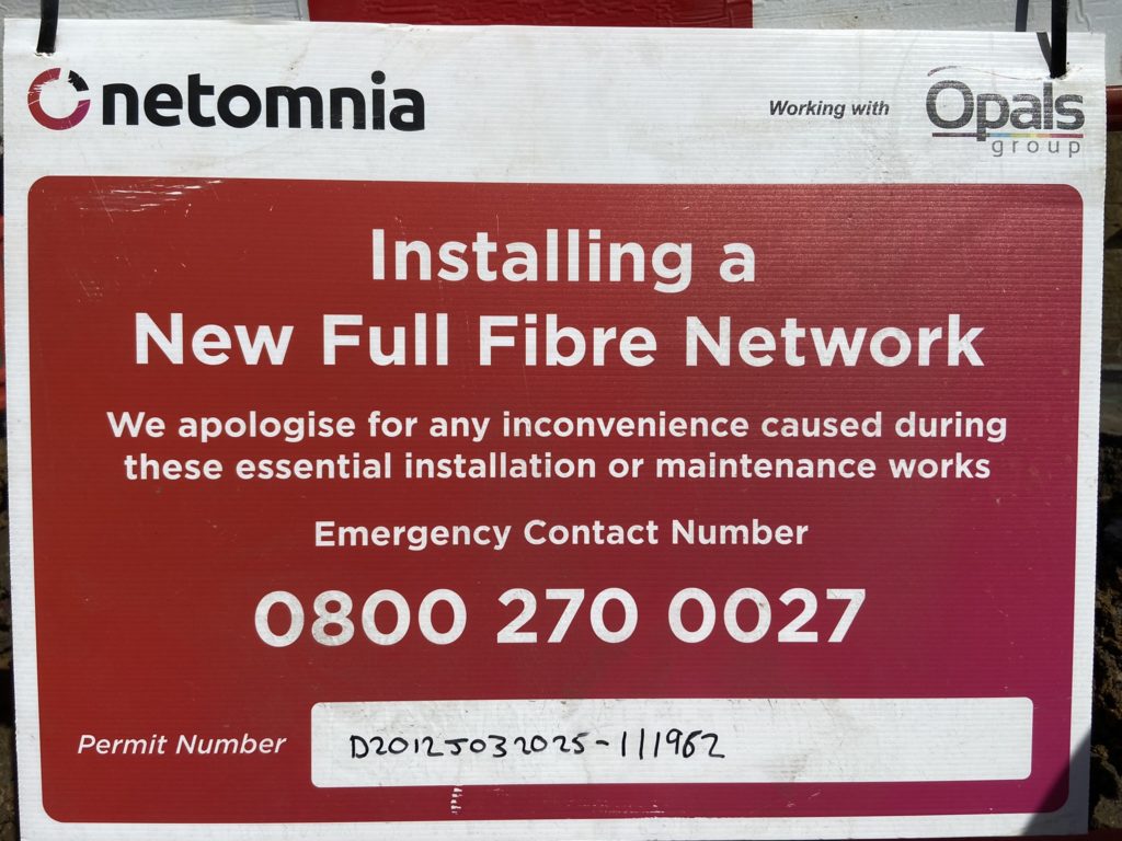
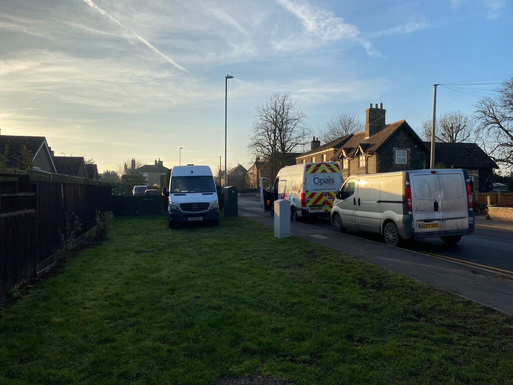
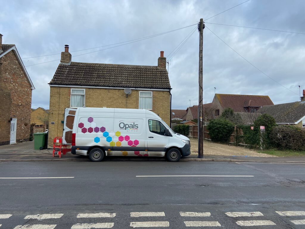
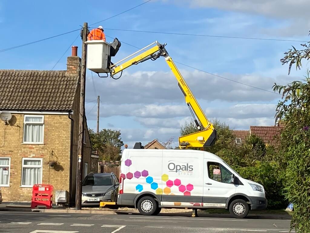
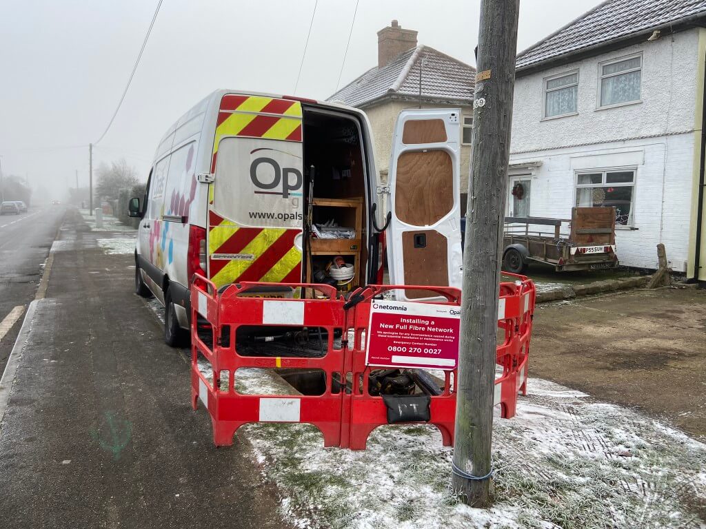
Netomnia are using Opals Group sold to OCU Group to undertake the work of installing the physical infrastructure to allow the fibre cables to be blown in at a later date.
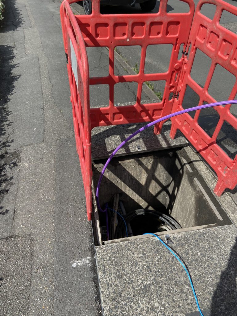
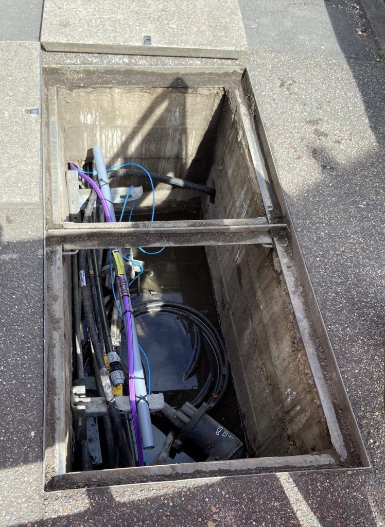
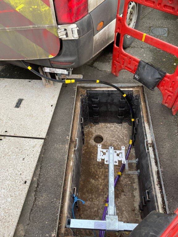
24th May 22 – Fiber optic sub duct being drawn into Openreach footway joint box.
24th May 22 – Second sub duct being pulled in to chamber
25th May 22 – Sub duct through connection point using push fit coupling.
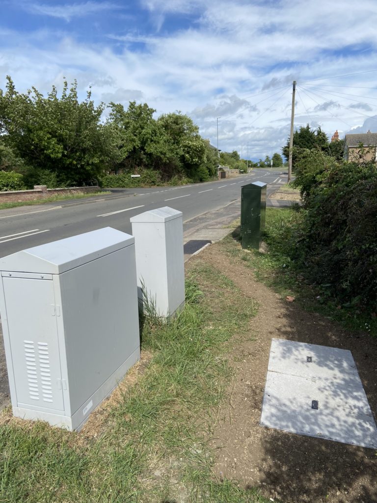
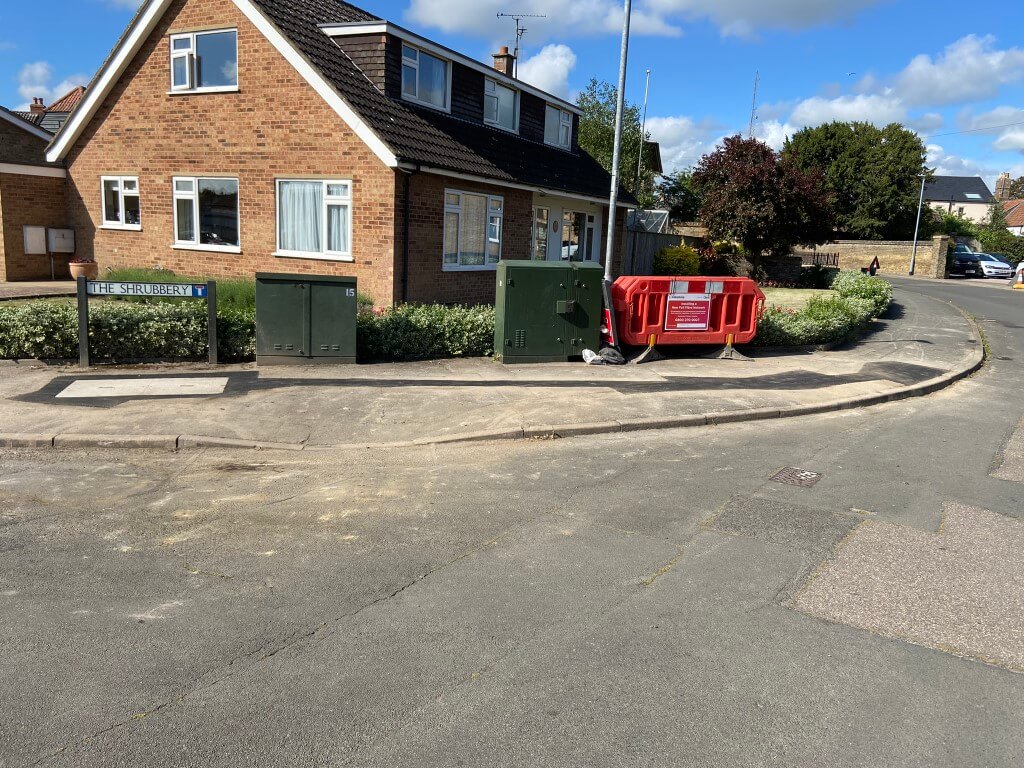
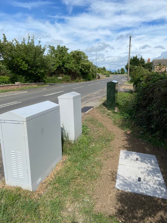
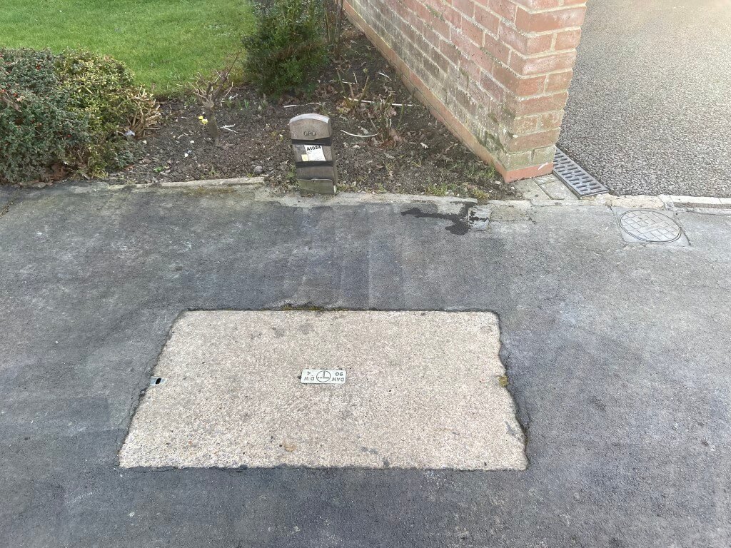
25thMay 22 – New Netomnia Footway Box installed in the verge, very neat job with the area re-seeded, this box is ducted to the Openreach footway box to allow interconnection. The two grey boxes belong to Virgin Media with the nearest one also being ducted to the Openreach footway box by the Green Openreach cabinet (PCP – Primary Cross Connection Point).
26th May 22 – Linking of an Openreach footway box with a new Netomnia footway L2/3 node point.
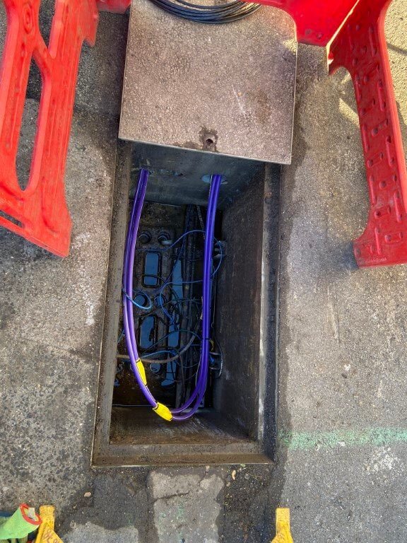
23 January 2023 – Purple Netomnia main spine micro-ducts looping through footway box.
27th May 22
Another new footway box going in, connected to an existing Openreach box, this activity is being replicated in many places across Chatteris and demonstrates considerable investment in infrastructure.
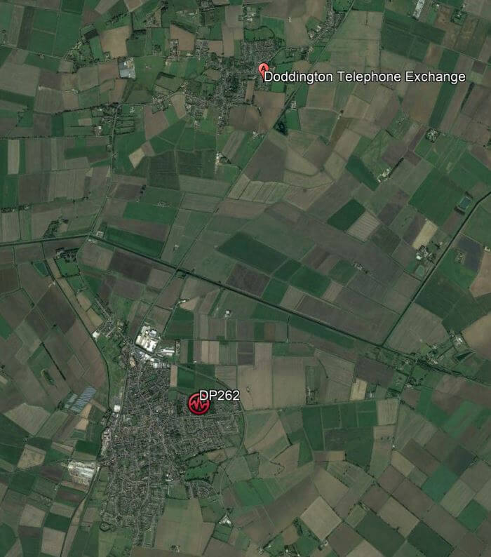
Netomnia network backbone fibre microtube link to carry a single fibre optic cable with 288 cores, being pulled in from Chatteris to the Doddington local head end ,or Level 0 which is in the Telephone Exchange.
Doddington Telephone Exchange
The microtube journey is in Openreach existing duct routes along Doddington Road, when Virgin Media followed the same route in 2017, they had to dig a new trench all the way, this is the massive benefit of the Physical Infrastructure Agreement.
Guide on installation of fibre cables by blowing – HERE.
6 July 2022
Opal engineers installing a Connectorised Block Terminal (CBT) in Farriers Gate footway box, the CTB which is stood up. belongs to Openreach, (I’m connected to it!), whilst the one lying on its side, belongs to Netomnia.
6th July 22
What is interesting to note is that both companies are using the same manufactures CBT, this must mean that the consumers installation process will be the same as that used by Openreach and described in my Talk Talk Future Fibre Blog.
6th July 22
8 August 2022
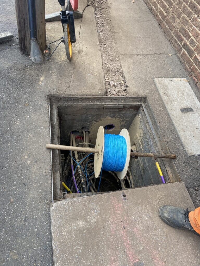
Civils contractors have started to excavate pavements to install new ducts (or tracks as Opal refer to them), where the existing Openreach ducts are either blocked or congested.
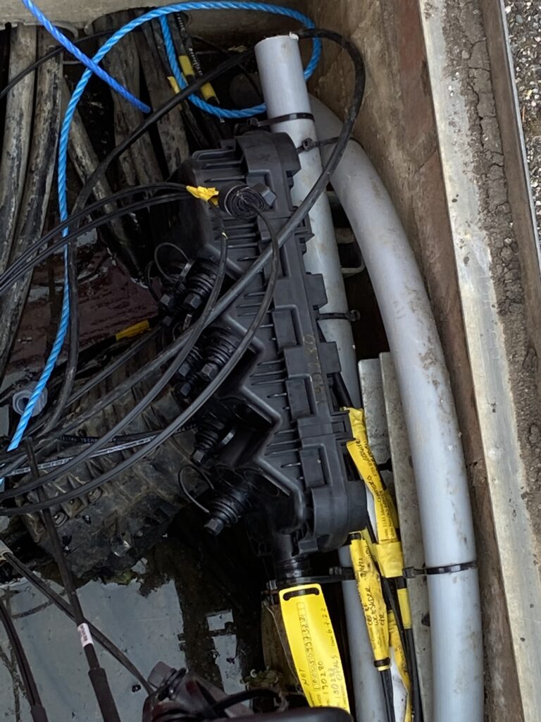
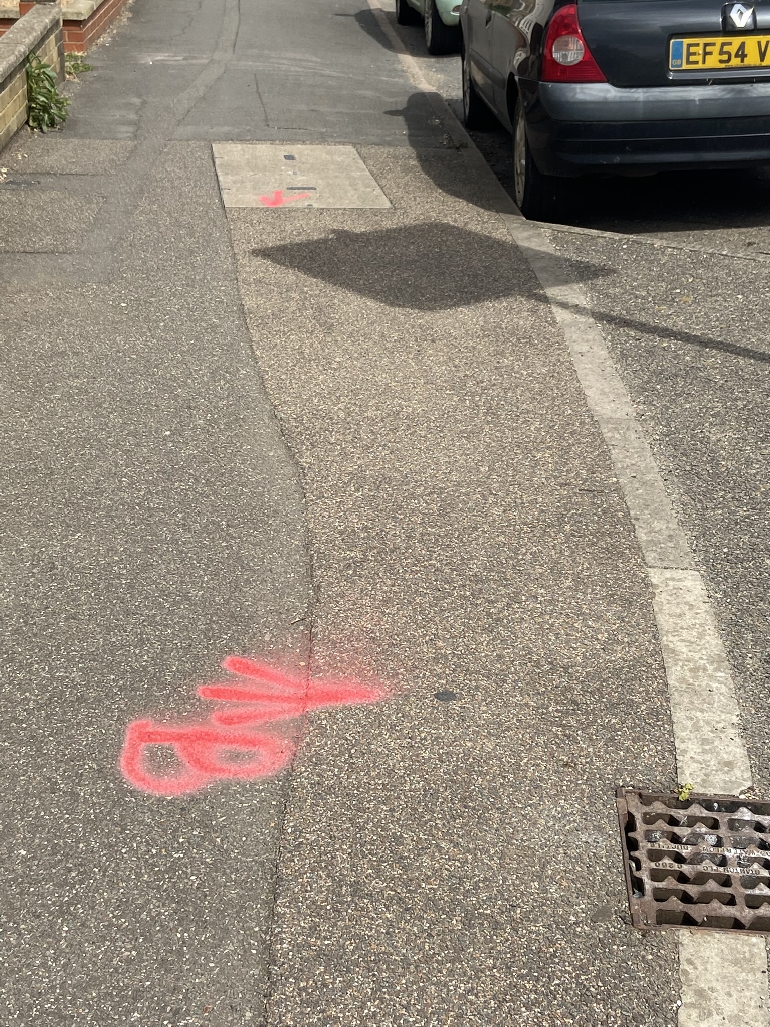
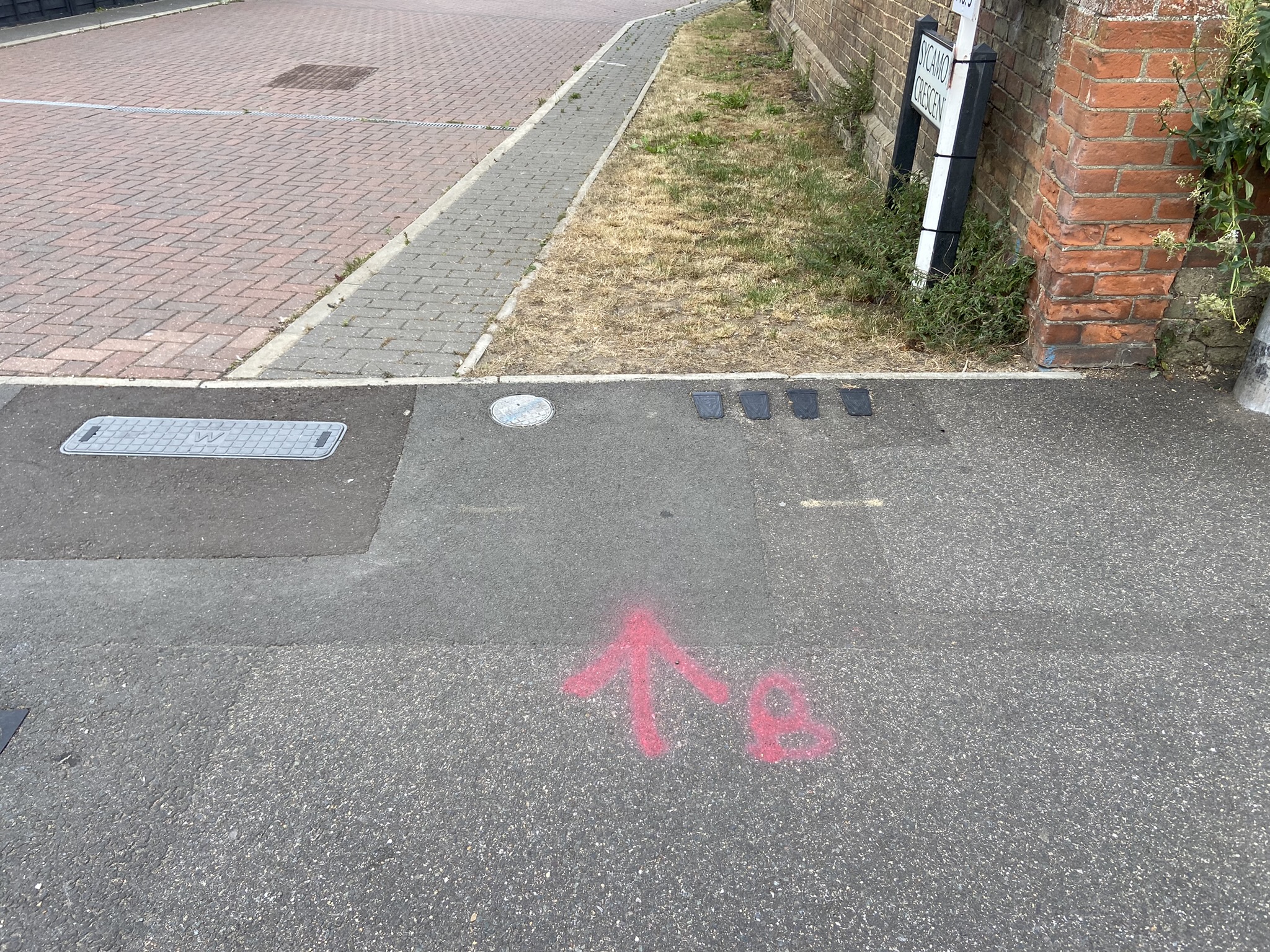
Blockages/congested routes are indicated by a red ‘B’ and direction arrows have popped up across the town ready for remedial works:
New Road, Netomnia ductwork infrastructure being installed where the existing Openreach route was congested.
13 September 2022
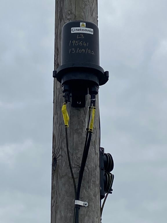
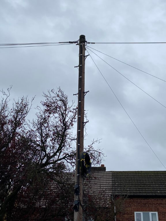
Installation underway of Netomnia Connectorised Block Terminals (CBT) on the existing telephone poles where the duct to the local footway box is available, this will enable subscribers with overhead lines access to ultrafast fibre optic broadband.
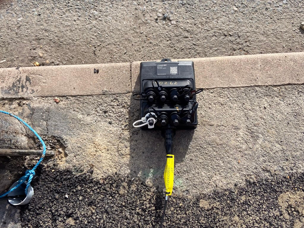
This images show two different versions of Netomnia installed standard 8 port CBT’s, details on fibre equipment can be found HERE, it is interesting to note that Openreach install up to 12 port units.
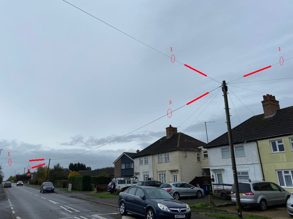
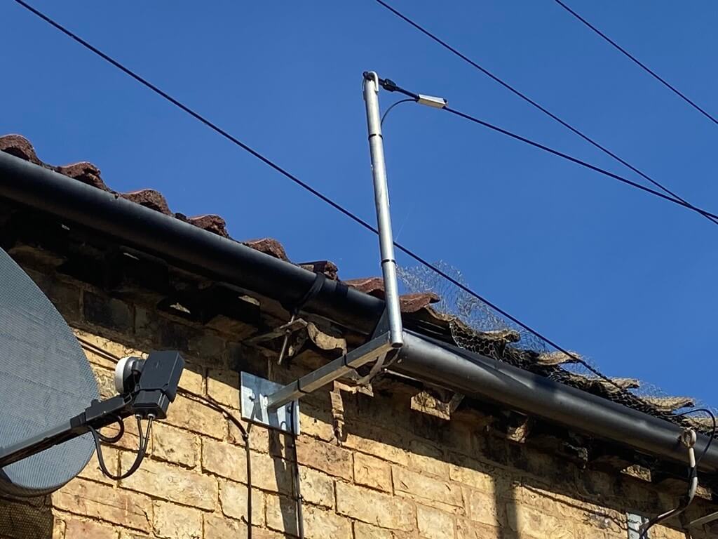
Pole evolution
Pole mounted splice enclosure, the two fibre cables on the right are from CBT’s, one on this pole, the other on another pole linked by an overhead connection.
One down, loads left to do
May 2022
Jan 2023
Jan 2023
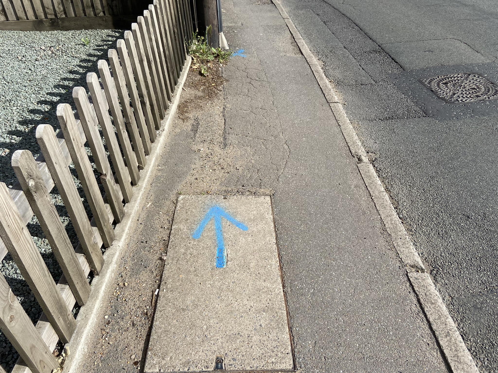
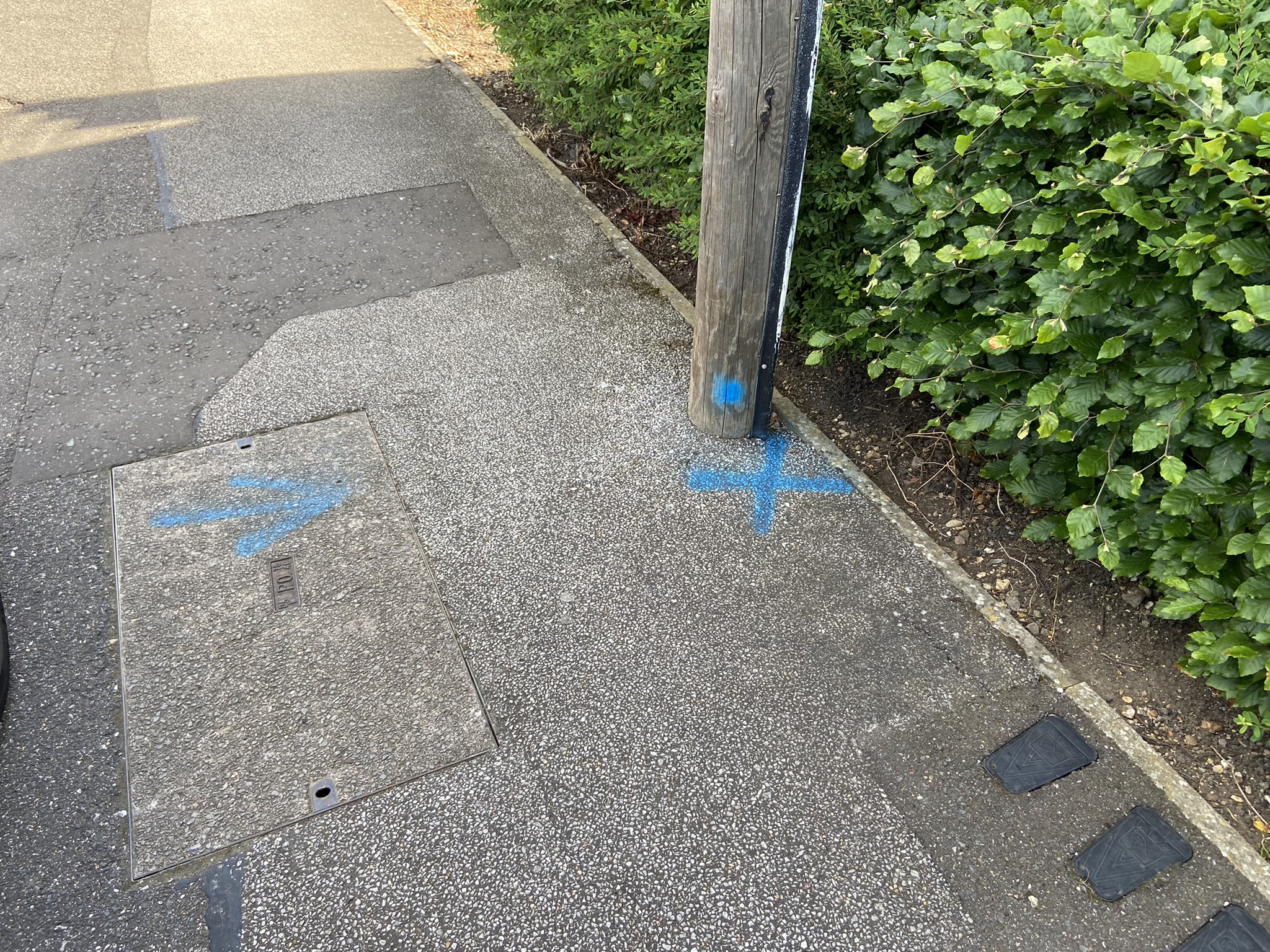
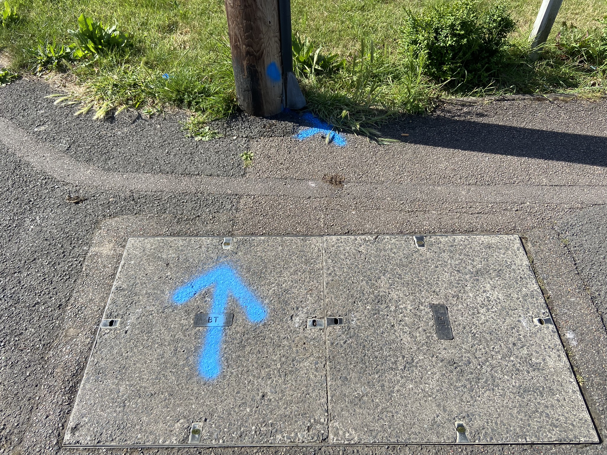
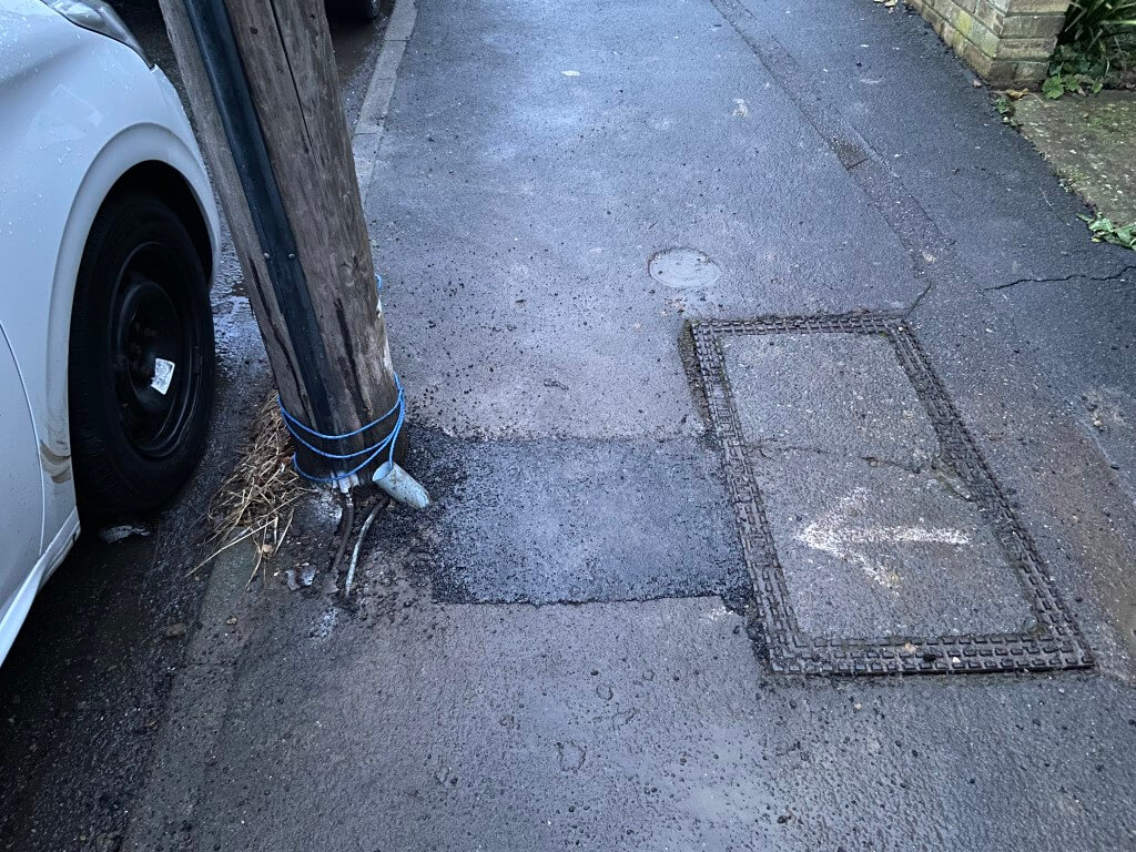
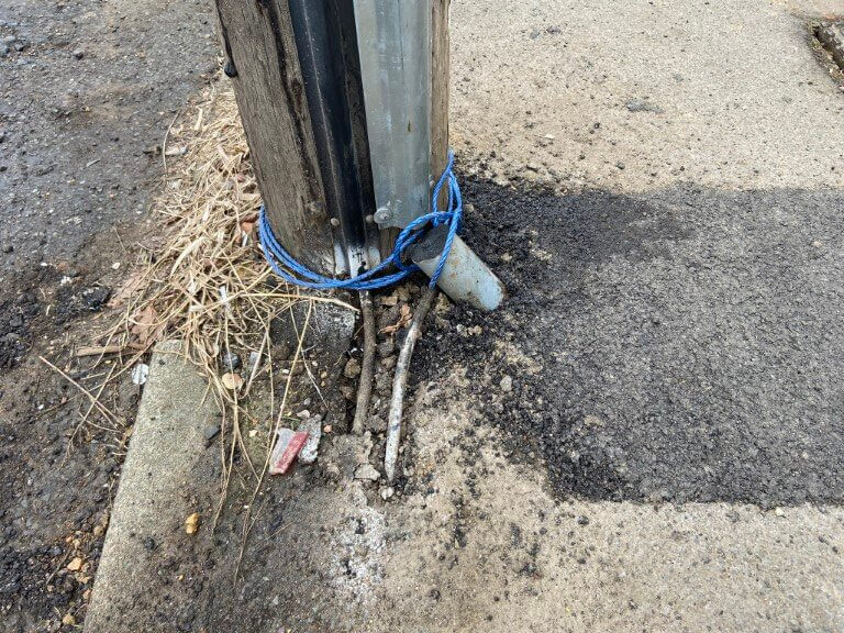
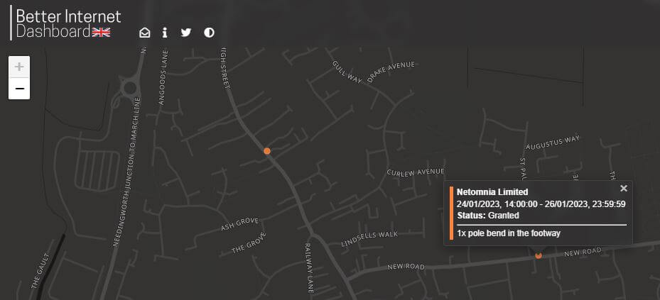
All around town a number of footway markings are appearing at the base of telephone poles, indicating that a new duct link (pole bend), to the nearest footway box is due to be made if no existing duct exists, or if the existing one is blocked or damaged.
The last three picture in the slide show above show the existing copper telephone cables feeding the pole are above the surface of the pavement, causing Netomnia to install a new pole bend bend:
Advance notice of civil works in New Road to the pole pictured in the slide show above.
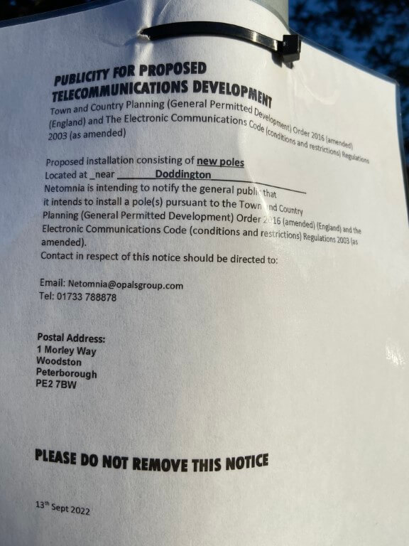
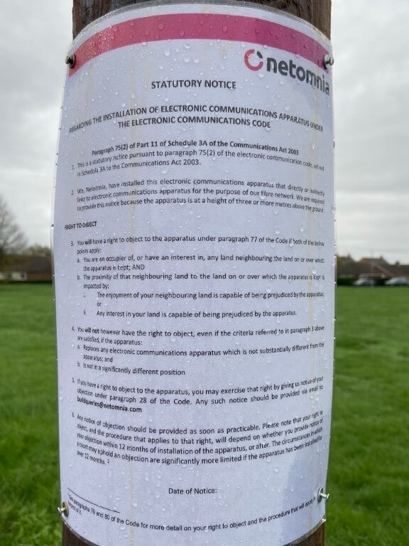
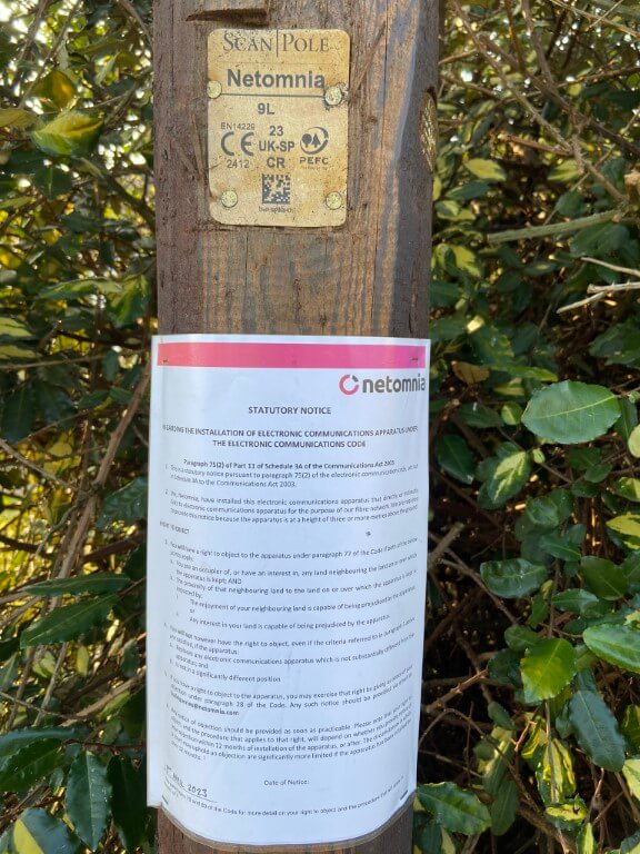
Netomnia advance notice indicating new poles are to be installed:
I contacted Netomnia on 16 September to gain further information, confirmation of 5 new poles to be installed was provided by Opals Senior Project Coordinator on the 28 September, the proposed ROUGH locations are:
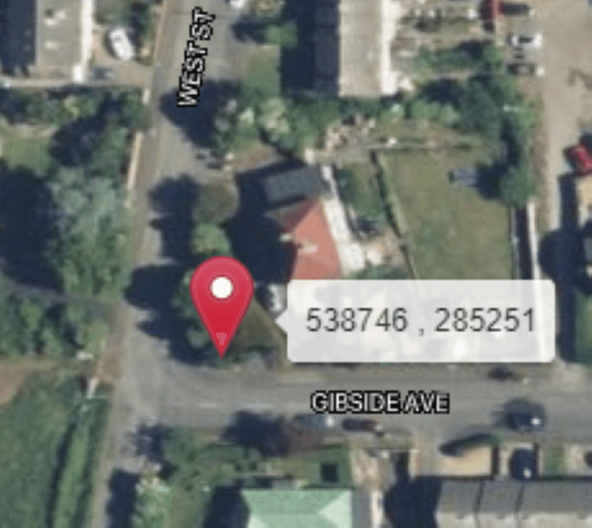
Corner of West Street and Gibside Avenue
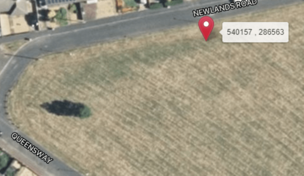
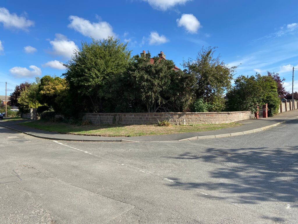
Newlands Road
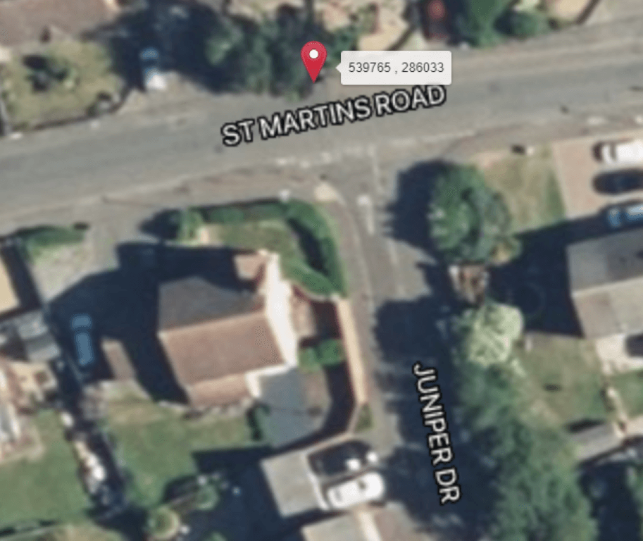
St Martins Road – Installation delayed – new pole application 13 Feb 23
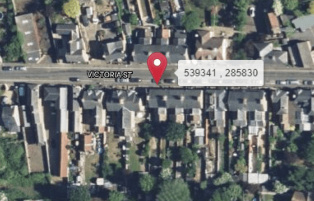
Victoria Street
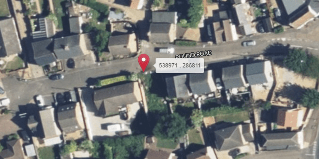
Pound Road – Installation not required, used long overhead span
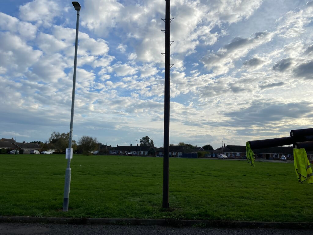
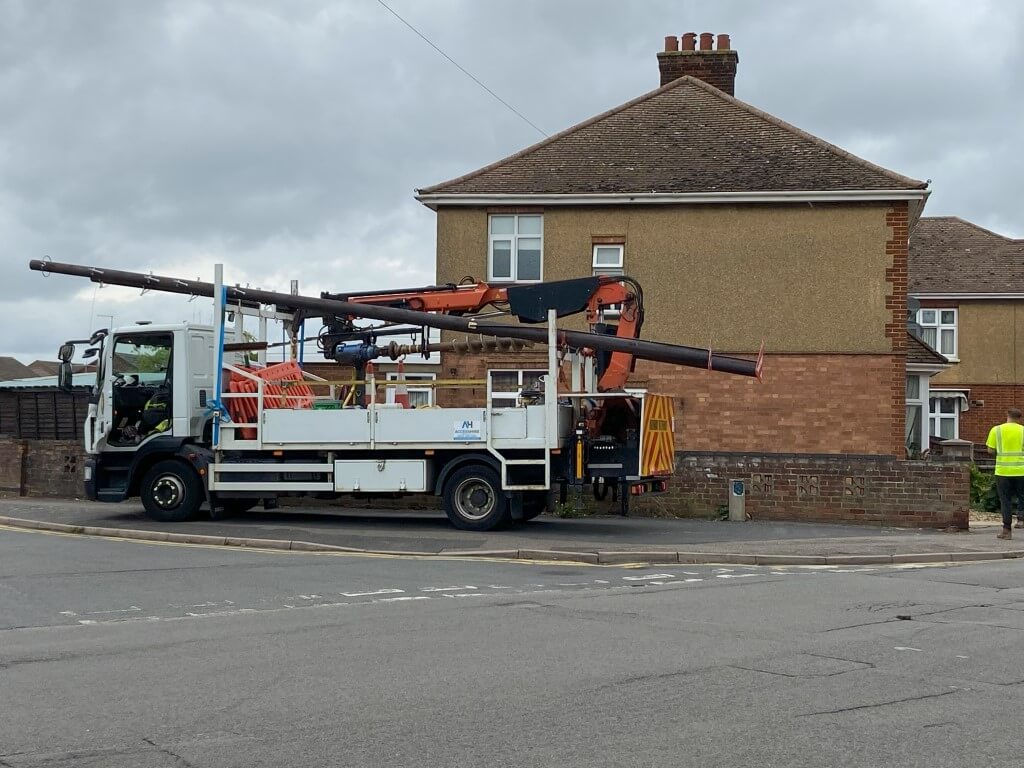
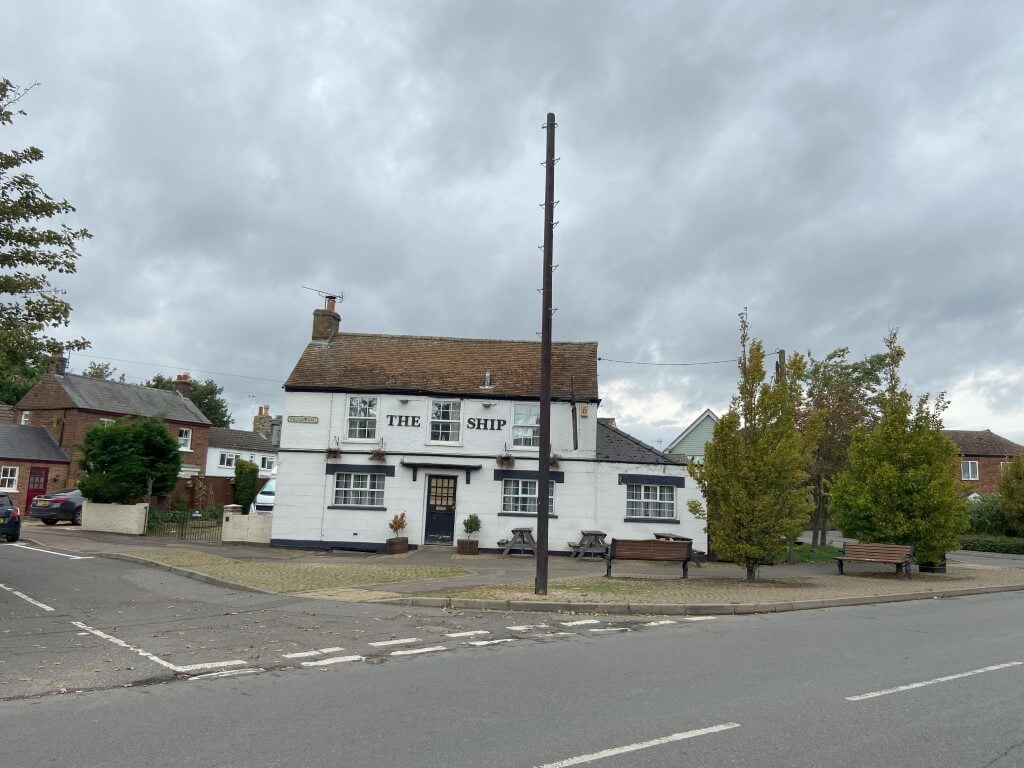
Update 27 October 22 – Netomnia Pole Installed, Gibside Avenue
Installed 27 October 2022
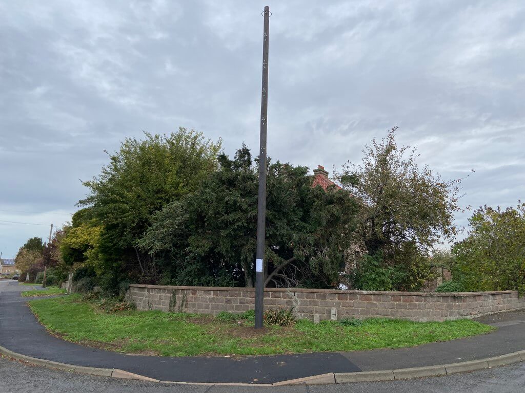
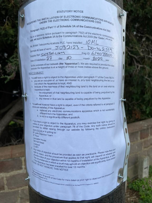
31 October 2022 – Newlands Road –
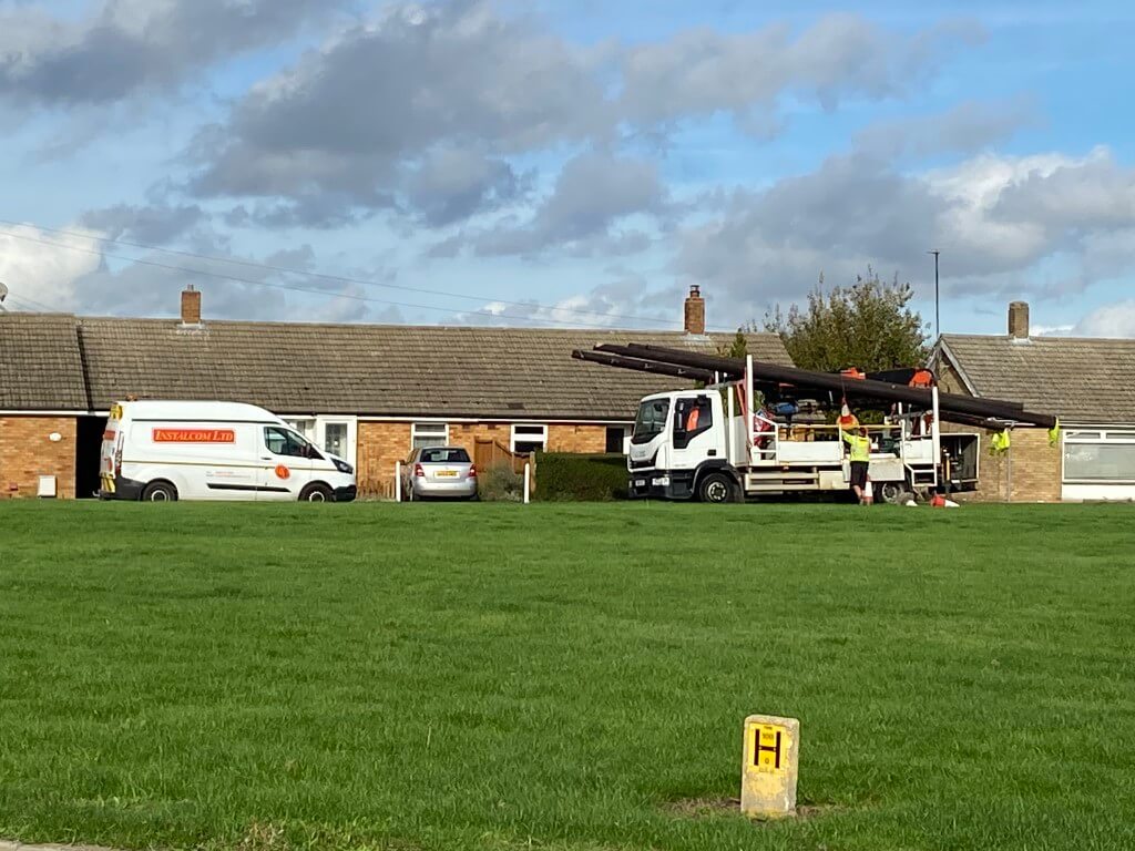
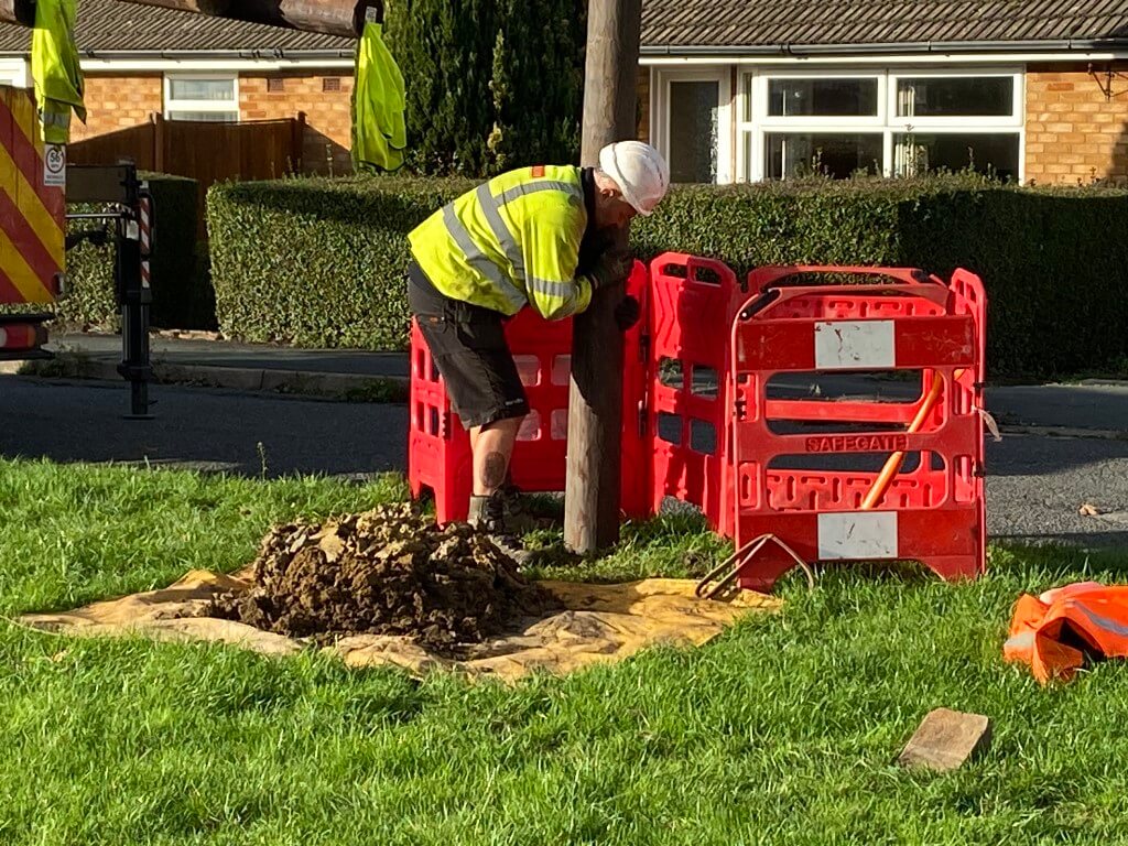
Ian and Steven were the technicians installing the 9 meter high pole working for Instalcom Ltd, they did a great job, were really friendly and customer focused. Brilliant ambassadors for Instalcom Ltd.
1 December 2022
With the imminent fibre spine link to Doddington being established after several delays due to duct damage/blockages meaning extensive civil works to rectify, their are at least two teams installing CBTs on existing telephone poles and a fibre technician has started splicing works from the CBT (Level 4) to the Level 3 node.
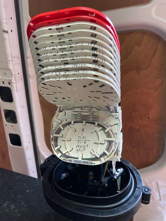
The image above is a fibre splicing enclosure (Level 3 Point), this example has 5 fibre cables, these are broken down as follows:
Two fibre cables are from two 8 port pole mounted CBTs (Level 4 ), depending on the CBT manufacture, of which Netonmia use two, either there will be one fibre spliced supplying all 8 ports due to an inbuilt optical splitter in the CBT or 8 fibres from each CBT port will need to be individually spliced to the fibre cable from the upstream Level 2 splicing connection.
Once completed, the enclosure will be stowed in a footway box making for a neat installation.
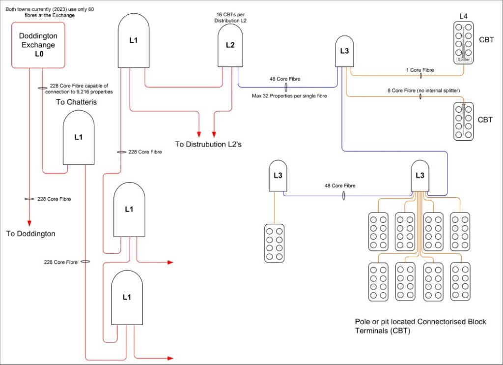
For clarity as I understand it, Level 0 is the origin of the fibre service which is Doddington Telephone Exchange, the main trunk cable from Doddington comprising of 288 fibres is terminated in a number of Level 1 hubs in Chatteris, 7 in total, 4 on the journey from Doddington and 3 in Chatteris.
Level 2 branches further sub divide into multiple Level 3 connections as above, before final connection to individual 8 port CBTs, Level 4.
8 Port Netomnia Connectorised Block Terminal ready for pole mounting.
From the CBT, this is the last leg of the fibre cable before it enters your property.
Each trunk single fibre can accommodate 32 properties, therefore the maximum number of properties served by one trunk cable is 9,216!
23 January 2023
The Netomnia network in Doddington is now LIVE and there is a real push to get Chatteris online after significant investment in installing new ducts due to the existing ducts being blocked/congested/damaged.
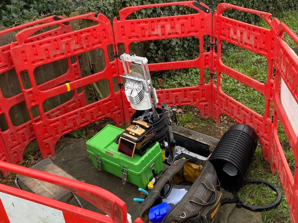
Technician fibre splicing the 288 core trunk fibre cable from Doddington exchange mid-way to Chatteris, the design of the system will allow for future expansion, to illustrate this, the whole of the current Doddington and Chatteris scheme only use 60 fibres in the exchange!
26 January 2023
Start of the Level 1 Chatteris core distribution fibre splicing to other L1 nodes, not all fibres are spliced through, only the ones required for this phase of the scheme as this saves both time and money:
L1 node being through spliced for distribution linking other L1 nodes to the network.
29 January 2023
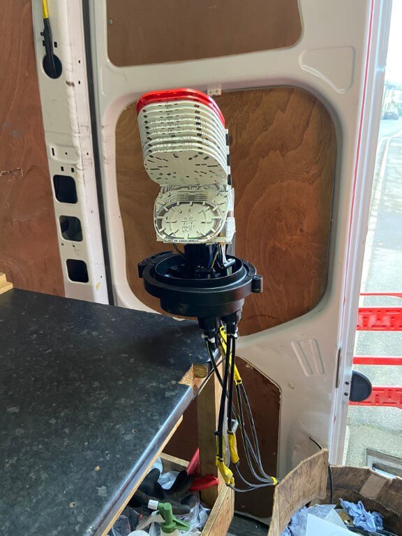
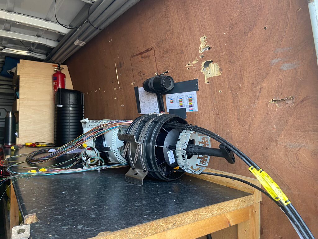
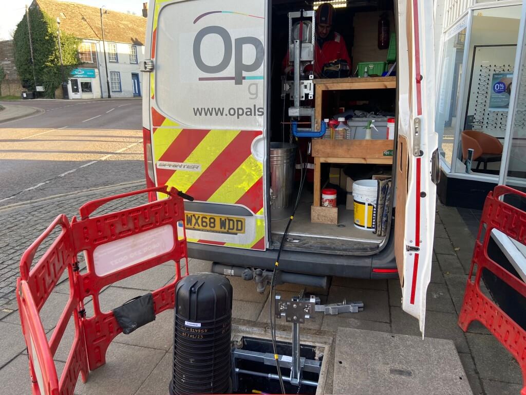
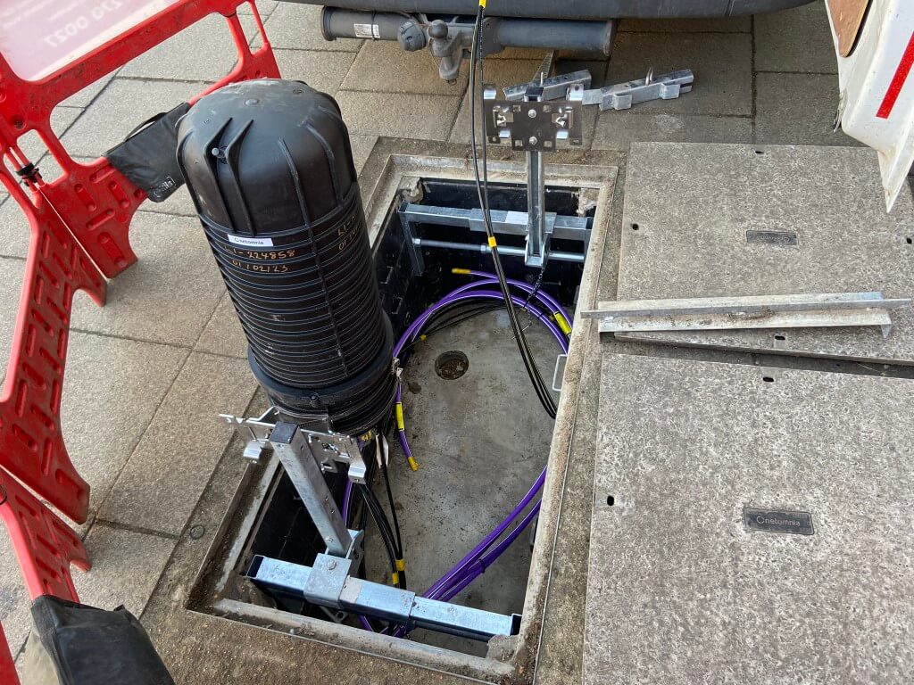
Level 2 (L2) Distribution node being spliced in the rear of a specially adapted vehicle, in the picture you can see a 44 core fiber which is black with a yellow tracer, this is from a L3 node, the other two black fiber cables are 288 cores linking further L2’s.
The L2 node will be located in a new Netomnia installed double footway box which was installed in May 2022.
1 February 2023
Caught up with the second splicing team who were working on the Level 3 (L3) terminations:
The picture shows two black with yellow tracer cables, each of which has 48 fibres, these are the interlinks to other L3 node fed from the L2 distribution node.
The tiny coloured tubes in the picture contain 12 fibres and each 48 core has 4 of these tubes.
The four clear tubes in the enclosure are from the pole mounted CBTs (L4), looking closely, one of these is a smaller diameter than the other three, this is due to the smaller tube only has one fiber in it as the 8 way pole CBT has an inbuilt splitter, whereas the other three have 8 fibers in the tube, one to each CBT port.
I did ask the reason for two differing types of CBT and the chap said is was due to how the network was designed.
Footway hardware ready to mount the completed L3 node so it can be neatly stowed.
9 February 2023
Plenty of continued activity by Opals Group, Netomnias infrastructure contractor, in New Road a footway box CBT was being relocated to another footway box due to the original box being over congested and not meeting the space requirements required by Openreach.
Further down the same road, a splicing technician was busy with a complicated L3 node.
10 February 2023
Notification of new pole installation in St Martins Road posted on the 10 February 2023, the first notification of a new pole in this location was on the 13 September 2022, but installation could not proceed as the proposed location did not give the required amount of room to pass on the pavement.
New pole position is on the opposite side of the road to the originally proposed location, position marked on the ground, (circle with a cross in it), next to the Virgin Media cabinet.
Around town, I also noticed a new sign dated 8 Feb 23, has been posted indicating the installation a new pole in Station Street.
14 February 2023
Lots observed today, L3 splicing by Aldi, fibre being blown in New Road, Level 2 (L2) splice being made off at the top of New Road and preparations being made by St Peters Drive/New Road for another L2 splice..
Big push to get Chatteris online me thinks!
Picture taken in May 2022 just after the Netomnia Footway Box had been installed.
Taken 9 months from the installation of the above footway box in New Road to L2 splicing.
Further down New Road, scoping for a L2 spice to be undertaken over the next day or so.
Junction of St Peters Drive/New Road.
The above picture shows the In & Out main 288 fibre core cable from/to other L2 splice enclosures (blown in purple duct), also you can see two 48 fibre core cables from L3 distribution splice enclosures all ready to be dressed ready for termination.
17 February 2023
Level 2 splice feeding Farriers Gate being undertaken, the fibres are live from Doddington, so as each fibre is spliced the light continues onto the next L2 /L3 & CBT.
Network deployment is progressing well in Chatteris, a few duct blockages to clear before the L3 fibres can be drawn in and connected.
In another part of the towns deployment is delayed due to scaffolding being built directly on top of a footway box, the Netomnia infrastructure team need to get a spine sub duct pulled through this in order to connect a Level 2 node.
Netomnia progress halted due to scaffolding in London Road.
The testing team for my area is due on Monday 20th February, where they will confirm satisfactory light levels at the CBT’s ready for customers connections.
19 February 2023
Sunday and three splicing teams are on the go in town, by Spectacular a Level 2 node was being spliced, the picture also shows a completed Level 1 node which feeds the Level 2 being worked on.
In the footway box is two empty purple sub ducts ready for the spine fibre to be blown in once the obstructing is cleared as written about on the 17th February.
23 February 2023 – NETWORK LIVE
The Netomnia network in Chatteris is now officially live after testing.
Netomnia technician removing a dust cap protecting a port on a CBT prior to connecting his test equipment.
Plugging his Exfo Optical Power Meter into the port he noted the reading of -20.35dB which was a pass, anything greater than -22.75dB is a fail.
His test confirms the correct optical signal level at the CBT from the Doddington exchange enabling sign off with the next step being canvassing for subscriber uptake.
1 March 2023
Opals engineers working to unblock a duct route to Fenton Way business area, the equipment costs £10k and is designed to push a heavy duty rod through obstructions, but not in this case 🙁 meaning a civils team will need to excavate and manually repair the ducting.
Just before coming across the guys rodding, I saw a Youfibre ‘door to door’ sales representative hard at work selling the benefits.
16 March 2023
Still lots of civil works bring Netomnia’s fibers to parts of the town once the duct restrictions have been resolved, as parts of Chatteris are now live, a mail drop has occurred enclosing the following leaflet:
This is probably the most important section of the blog as customer satisfaction in such a crowded marketplace is crucial, as bad news travels fast.
I’ve attached, (with the authors permission and my thanks), unabridged Facebook comments on their experience and performance using YouFibre:
Mr Green
Mr Naisbett
Mr Thompson
My order was delayed by quite a bit, (original install date in September last year) but it finally got put in a couple weeks ago. There was the big hold up at the other end getting it connected but once things were rolling and I got the all green, they came and did the outside line (annoyingly without prebooking, but whatever) that took like 10 minutes. Much less faff than Virgin Media. And then their install lads came and sorted me out a few days later of an evening.
Polite and friendly on all occasions, they made it clear they don’t actually work for YouFibre though, and that at times they don’t get all the information they should have, so please do be patient with them if they don’t have 100% correct info, that sounds like it’s on YouFibre’s call centre.
I wasn’t aware of them using a strange NAT setup so thanks whoever it was pointed that out, I was hoping to avoid getting a static IP but if I need that to break through a forced NAT then sobeit.
Speed has been excellent so far, I got their YouMesh thing with the 1Gb Service, which is a bit paradoxical given you can only get 250Mb from the ‘Nodes’ even if you use a cable, which is a bit silly, so I’ve unplugged those and just use the Eero main hub for now. I’ll be plumbing it into my own Mesh later once I’ve got the time, but for now, happily getting 750Mb + both ways via WiFi on a WiFi 6 connected device that’s not exactly right next to it, so pretty pleased with that.
Haven’t tested the latency extensively, given I’m on WiFi currently that seemed pointless to do yet, may report back with findings at a later point.
Definitely recommend them, they’re less than half the price of Virgin Media and that’s excellent for a symmetrical line in the UK. I just hope they prove to be as popular as they should be and spread to other areas, the UK needs more competition in the broadband Market, BT only do the bare minimum and VM are just pricing things stupidly.
18 April 2023 – Another New Pole
Two new poles were installed today on behalf of Netomnia, (Park Street and St Martins Road), these will be used as transit poles to reduce the overhead fibre span distance to the next pole/other poles having CBTs fitted.
Guys setting up for the installation, the difference between these poles and the one installed in Newlands Road is that it came complete with pole hardware already fitted, (steps & top ring), and it also bears the name of the provider.
11 October 2023 – New Poles
Two new transit poles have been installed today carrying overhead fibre optic cables to enable service connections to be available on existing poles:
Corner of Railway Lane and Horsegate Gardens.
New pole outside The Ship, a further pole is due for installation in the town but I do not have the location at the time of this update.
Their are only two options, the fibre either goes above or below ground!
Netomnia are able to use existing Openreach underground ducts which brings your telephone line to your house, these same ducts are used to draw in a new fibre optic cable which terminates directly inside your home.
It might be the case that your existing telephone cable does not use a duct and the cable is ‘directly buried’ in the ground, I’m not sure how Netomnia would tackle this if you wanted the service, they may opt to install a new telephone pole, and use overhead lines to your house from this.
Above ground junction box is a typical indication that the phone lines to properties are directly buried.
Virgin Media use ‘directly buried’ micro ducts from the pavement ‘Toby boxes’ to your house external wall to bring their fibre to the house, but they are the only provider to do so as I understand it.
If your telephone line comes in overhead, then a fibre optical cable will use the same method, as long as the pole has been enabled with the network hardware.
This telephone pole is nearest to where I live so it was quite easy to monitor its progress:
25th May 22, Sub Duct installed to upstream footway box
26th May – 29th May, New double footway box installed near pole DP262
11th June, floor markings appear indicating the pole needs a new duct installing
22nd August, Opals civils install new duct to pole DP262
11th October, pole CBT installed
17th February 23, L2 splicing to make pole live for testing on the 20th February.
24 August 22, work to install new duct to pole
Opals engineer installing the CBT, no ladders are used on the pole, all work was carried out from the vehicles bucket.
23 January 2023, fibre cable being blown to L2 node in New Road.
For a sense of scale, the Chatteris scheme including DP262 is fed from Doddington Exchange.
23 January 2023 – Netomnia trunk fibre being spliced through in Doddington Road, you might just be able to make the technician out in the copse.
Pole Mounted CBT Connection to L3
The fibre cable to the pole CBT in the above image was neatly clipped down the pole and ran in a new duct to a footway box for splicing and this method is adopted where duct access is available.
Another method Netomnia employ to get a CBT fibre cable to a pole or number of poles is overhead, this could be due to duct blockages, duct capacity issues or financial considerations based on time.
The above picture is of an existing Openreach Pole in Fairway with three telephone lines fanning out to the right, the horizontal cables at the top of the pole are fibre cables to other pole mounted CBTs, from this pole you can see that six CBTs will be spliced here.
Another example from New Road where the fibre for five other pole CBTs are fed overhead and will be terminated in a footway box near the base of the main pole in the picture.
14 December 2022, external temperature -5oC and fibre splicing continues.
Technician splicing 6 fibres, (5 plus 1 from the poles CBT), New Road.
Fibre/Broadband equipment in the home
Based on information from forums on Youfibre installation, the feedback is very positive in other towns.
Very little information regarding Youfibre installations exists currently on the internet, probably due to the company only relatively recently formed.
The fibre can get to the property either via the existing telephone duct or via overhead from the same pole as your phoneline,.
The externally graded fibre is spliced in an enclosure to a fibre cable suitable for installation into the property.
Youfibre standoff bracket designed to bring an overhead fibre from the nearest pole whilst coping with the gutter overhang.
Images of different Customer Service Points used by Netomnia.
Simon kindly sent the image of his YouFibre CSP which was cabled from a footway box CBT.
Picture taken 13 July 2025 – Netomnia Customer Spice Point lid damaged, interesting to see the Openreach internal telephone cables hanging out, sign of the times 🙂
Information on the difference between OLT and ONT – HERE.
The type of ONT used is Adtran SDX 622v they’ll provide this if you take their phone or 10G service else it’s a Adtran 621i.
Images above are of the Adtran 622v.
Simon kindly sent me the image of his neat YouFibre Adtran SDX-662v.
Hub
Youfibre supply a eero Pro according to their website, the manual link is HERE.
The ONT needs a power socket as does the eero hub, so wherever you want the service to go, check you have a free double socket.
Eero Pro (stock image)
Equipment Failures!!
16 July 2025 – I naively thought that a passive optical network would last a considerable length of time, considering all the external equipment is suitably ruggedized for the conditions in which the kit is exposed.
A friend who lives on the same street but using a different CBT, asked if my connection was ok as his ONT is flashing between green and red on the optical LED.
An engineer arrived quickly and determined that his signal strength, which was between -18db and -22db on installation had dropped to an unacceptable light loss of -25db, the engineers conclusion after fault finding was that the CBT in the street footway box needed replacement.
Love the kneeling pad, so 70’s
The CBT is hidden be other equipment, however, you can see the ‘Light Pen’ which is connected the CBT via a patch lead, this will enable the engineer to locate the correct fibre at the the other footway chamber where this originates.
The process will be that a new pre-terminated CBT fibre cable will be pulled in and spliced, getting the subscribers on the faulty CBT there service back.
This seems to be a common mode problem, as the engineer commented that two CBT’s were changed yesterday with the same symptoms, it must be noted that rectification of the problem was swiftly executed, so well done to all for that.
27 August 2025 – Across the street from the earlier CBT failure another has occurred, seemingly a bad batch?
A blog about stuff that interests me or I have done.
We use cookies on our website to give you the most relevant experience by remembering your preferences and repeat visits. By clicking “Accept All”, you consent to the use of ALL the cookies. However, you may visit "Cookie Settings" to provide a controlled consent.
This website uses cookies to improve your experience while you navigate through the website. Out of these, the cookies that are categorized as necessary are stored on your browser as they are essential for the working of basic functionalities of the website. We also use third-party cookies that help us analyze and understand how you use this website. These cookies will be stored in your browser only with your consent. You also have the option to opt-out of these cookies. But opting out of some of these cookies may affect your browsing experience.
Necessary cookies are absolutely essential for the website to function properly. These cookies ensure basic functionalities and security features of the website, anonymously.
Cookie
Duration
Description
_GRECAPTCHA
5 months 27 days
This cookie is set by the Google recaptcha service to identify bots to protect the website against malicious spam attacks.
cookielawinfo-checkbox-advertisement
1 year
Set by the GDPR Cookie Consent plugin, this cookie is used to record the user consent for the cookies in the "Advertisement" category .
cookielawinfo-checkbox-analytics
11 months
This cookie is set by GDPR Cookie Consent plugin. The cookie is used to store the user consent for the cookies in the category "Analytics".
cookielawinfo-checkbox-functional
11 months
The cookie is set by GDPR cookie consent to record the user consent for the cookies in the category "Functional".
cookielawinfo-checkbox-necessary
11 months
This cookie is set by GDPR Cookie Consent plugin. The cookies is used to store the user consent for the cookies in the category "Necessary".
cookielawinfo-checkbox-others
11 months
This cookie is set by GDPR Cookie Consent plugin. The cookie is used to store the user consent for the cookies in the category "Other.
cookielawinfo-checkbox-performance
11 months
This cookie is set by GDPR Cookie Consent plugin. The cookie is used to store the user consent for the cookies in the category "Performance".
CookieLawInfoConsent
1 year
Records the default button state of the corresponding category & the status of CCPA. It works only in coordination with the primary cookie.
PHPSESSID
session
This cookie is native to PHP applications. The cookie is used to store and identify a users' unique session ID for the purpose of managing user session on the website. The cookie is a session cookies and is deleted when all the browser windows are closed.
viewed_cookie_policy
11 months
The cookie is set by the GDPR Cookie Consent plugin and is used to store whether or not user has consented to the use of cookies. It does not store any personal data.
Functional cookies help to perform certain functionalities like sharing the content of the website on social media platforms, collect feedbacks, and other third-party features.
Performance cookies are used to understand and analyze the key performance indexes of the website which helps in delivering a better user experience for the visitors.
Analytical cookies are used to understand how visitors interact with the website. These cookies help provide information on metrics the number of visitors, bounce rate, traffic source, etc.
Cookie
Duration
Description
_ga
2 years
The _ga cookie, installed by Google Analytics, calculates visitor, session and campaign data and also keeps track of site usage for the site's analytics report. The cookie stores information anonymously and assigns a randomly generated number to recognize unique visitors.
_ga_92TJCVGJP2
2 years
This cookie is installed by Google Analytics.
_gat_gtag_UA_48800884_1
1 minute
Set by Google to distinguish users.
_gid
1 day
Installed by Google Analytics, _gid cookie stores information on how visitors use a website, while also creating an analytics report of the website's performance. Some of the data that are collected include the number of visitors, their source, and the pages they visit anonymously.
CONSENT
2 years
YouTube sets this cookie via embedded youtube-videos and registers anonymous statistical data.
is_unique
5 years
StatCounter sets this cookie to determine whether a user is a first-time or a returning visitor and to estimate the accumulated unique visits per site.
is_visitor_unique
2 years
StatCounter sets this cookie to determine whether a user is a first-time or a returning visitor.
sc_is_visitor_unique
2 years
StatCounter sets this cookie to determine whether a user is a first-time or a returning visitor.
Advertisement cookies are used to provide visitors with relevant ads and marketing campaigns. These cookies track visitors across websites and collect information to provide customized ads.
Cookie
Duration
Description
NID
6 months
NID cookie, set by Google, is used for advertising purposes; to limit the number of times the user sees an ad, to mute unwanted ads, and to measure the effectiveness of ads.
VISITOR_INFO1_LIVE
past
A cookie set by YouTube to measure bandwidth that determines whether the user gets the new or old player interface.
YSC
session
YSC cookie is set by Youtube and is used to track the views of embedded videos on Youtube pages.
yt-remote-connected-devices
never
YouTube sets this cookie to store the video preferences of the user using embedded YouTube video.
yt-remote-device-id
never
YouTube sets this cookie to store the video preferences of the user using embedded YouTube video.
yt.innertube::nextId
never
This cookie, set by YouTube, registers a unique ID to store data on what videos from YouTube the user has seen.
yt.innertube::requests
never
This cookie, set by YouTube, registers a unique ID to store data on what videos from YouTube the user has seen.