Updated 6 January 2026
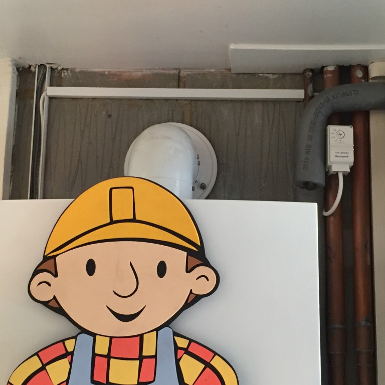
Due to the recent cold snap and the fact that my central heating boiler is in the garage, I thought I’d install frost protection which will override the heating controls and fire up the boiler when the frost stat air temperature is at or below +5℃, on the return pipework to the boiler is pipe stat set for +25℃ to turn the boiler off.
I have a Hive system which has a frost setting on the internal thermostat, this will bring the heating on if the temperature falls to +7℃ or below, the garage frost protection supplements this.
I spotted the Honeywell Frost Protection Kit – K42008628-001 comprising of a Frost Stat and Pipe Stat for £27.00 on eBay which is a really good price compared to Screwfix, Plumbase and Toolstation, so I bought it.
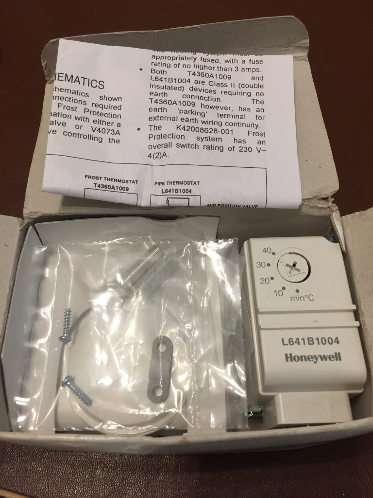
For the installation, apart from the stats, I needed some heat resisting cable for the pipe stat and a double mounting box.
2 core and earth (3093Y) 0.75mm2 heat resisting white round flexible cable was bought off the internet from Under Control Instruments (www.undercontrol.co.uk) for £4.00 which is temperature rated to 85℃.
The double gang surface box took a little bit of searching as I needed one with the flexibility to be used either vertically or horizontally with face-plates in the correct orientation, this cost £3.99 off eBay.
First job was to wire the pipe stat and install it on the return pipe to the boiler, the stat is held in place with a spring which hook onto lugs on the base of the stat, getting the spring behind the pipe and stretching it to fit was made easier by tying a piece of string to one end of the spring and passing that behind the pipe.
Hooking the spring on the stat lug and keeping tension on the string, offer the stat to the pipe and pull the string to stretch the spring round the back of the pipe and hook it on the opposite lug, once done the string is simply cut off, this worked very easily once you got the knack.
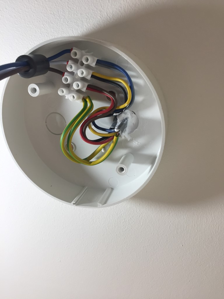
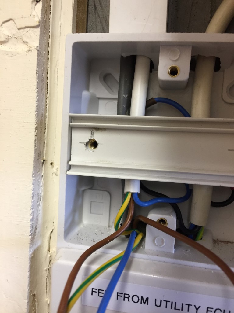
With the power isolated, the existing isolator was opened and a picture taken for reference.
The Blue (Neutral (N)), Yellow (system calling for heat – switched 230v (L2)) and Red (Live (L1)) are from the junction box wiring centre, the opposing wires in the isolator are to the boiler.
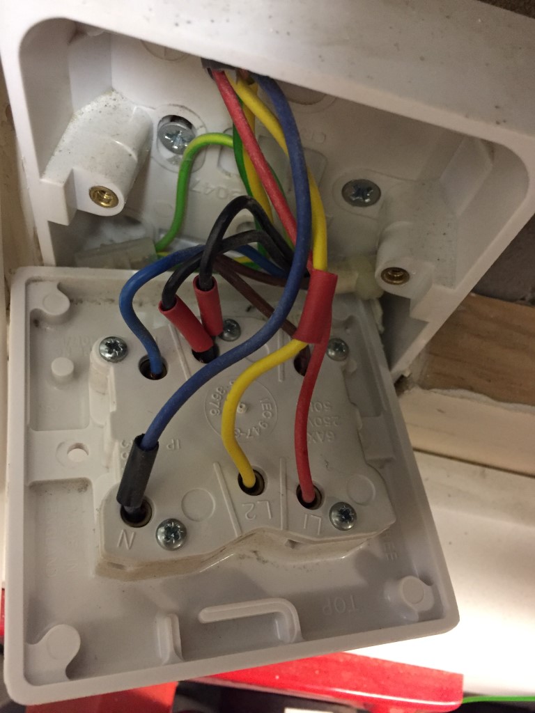
Once everything was identified and proved dead, the wiring was removed and the new double gang surface box was fitted and wires pulled back in.
The two red sleeved blacks were separated, one will be connected back into L2, the other will be used by the frost protection system.
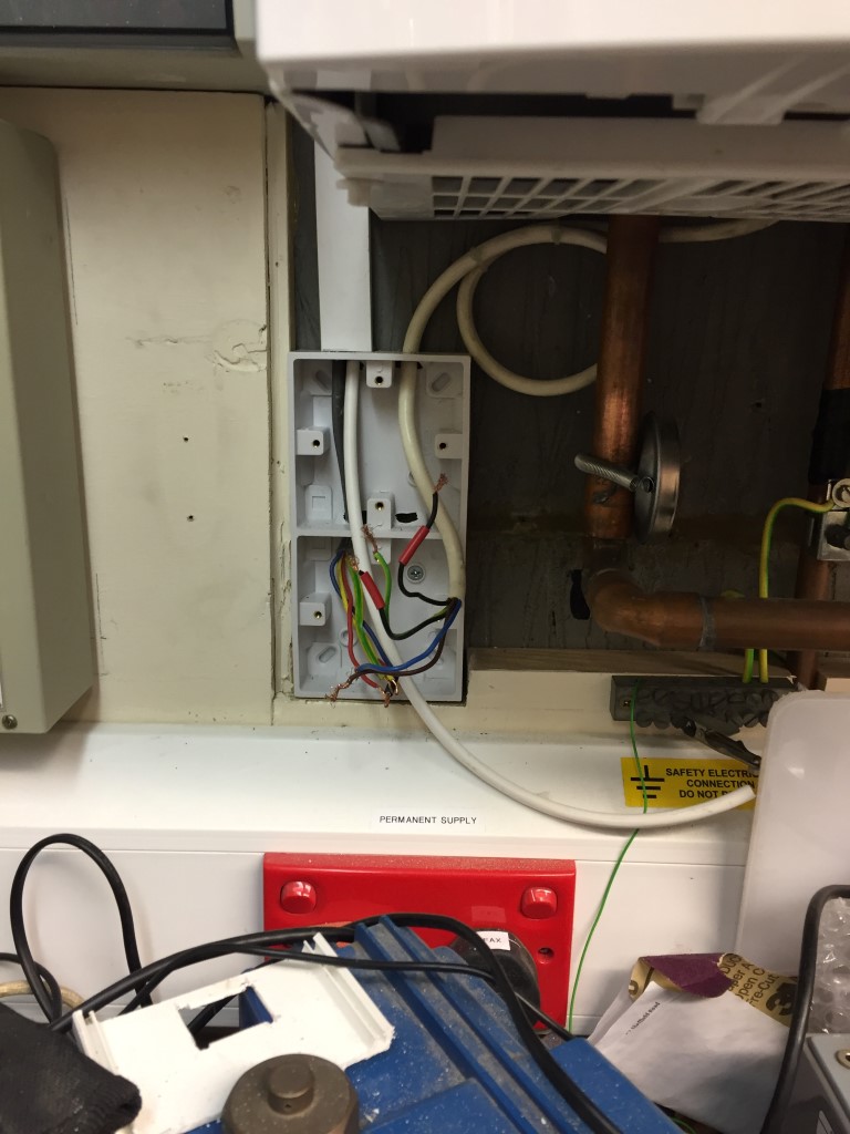
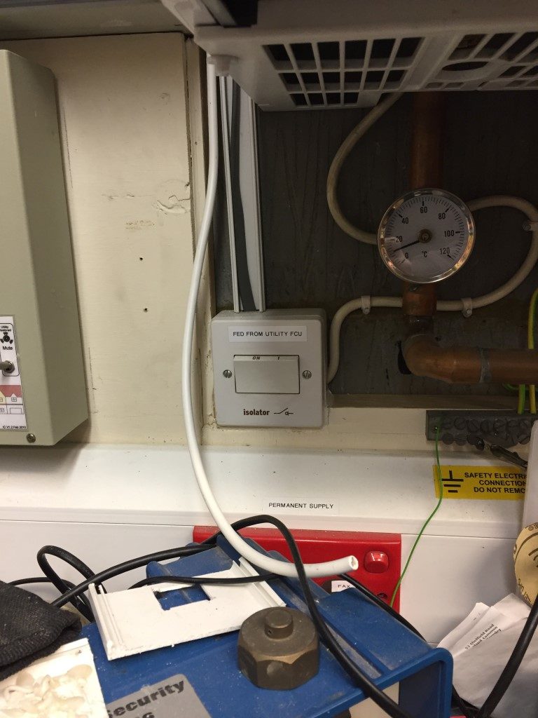
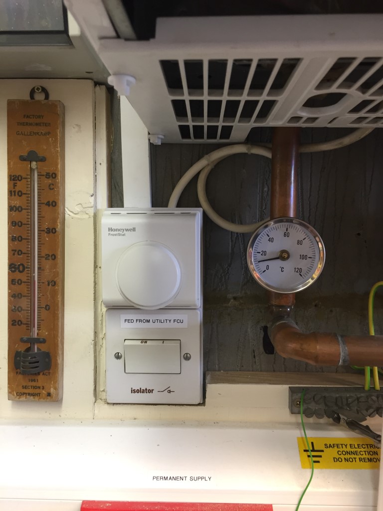
The isolator was wired up and screwed into place, then the frost stat was fitted but it did not sit right as it was very slightly smaller than the back box so I needed packing to make it level, for this I used an off-cut of trunking lid, which did the trick.
Once the Froststat was fixed in place and connected, the power was turned on and the frost protection tested by simulation that everything worked ok, including the operation of the Automatic Bypass Valve, once done the trigger temperature was set and the stat lid fixed in place.
I did notice a draft from behind my changeover switch on the left of the picture which was blowing across the face of the froststat, so I sealed the gap with decorators caulk to avoid inaccurate operation of the stat.
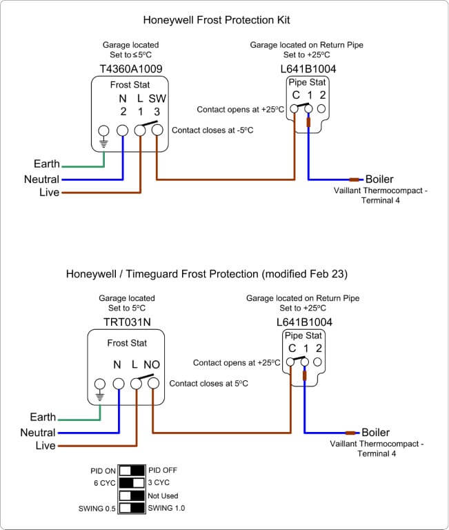
As I have recently installed an Automatic Bypass Valve, I have not connected the frost stat to any motorised zone valves, therefore, once the air temperature is at or below +5℃, a switched live will be applied to the boilers ‘calling for heat’ via the red sleeved black wire, the boiler will now fire and the circulation pump will operate.
As the motorised valves to either the central heating or hot water cylinder will be closed (‘S’ Plan system), the pumped water pressure will ‘lift’ the automatic bypass valve, maintaining a heated water flow to the boiler via the return pipework to which the pipe stat is affixed.
Once the return pipework is above +25℃, the pipe stat opens the series wired connection from the frost stat, this removes the switched live to the boiler, and the boiler enters ‘no heat run on mode’ before switching off.
The job took 2 hours and cost £35.00 and although we have never had a problem, the boiler and pipework in the garage should have had effective frost protection from day one.
Update
19 March 18 – The boiler came on unexpectedly and it was caused by the frost stat, closer inspection reveled that one of the bimetallic switch support pillar was snapped inside the unit, I’ve contacted the seller on eBay to see if I can get a replacement.
20 March 18 – eBay seller responded to my mail and is sending a replacement unit out.
24 March 18 – Replacement froststat arrived in good order and installed, all working now and the original unit sent back to the seller.
15 December 2022 – Had a few really cold days of around -5oC and the garage internal temperature sensor was reading 4.25oC
I took the cover off the frost stat and I must have moved the dial when I was replacing the lid as it was set below +5oC, I have readjusted this now, so all should be good.
3 February 2023 – Timeguard TRT031N electronic frost thermostat arrived from Fastlec at a cost of £22.36.
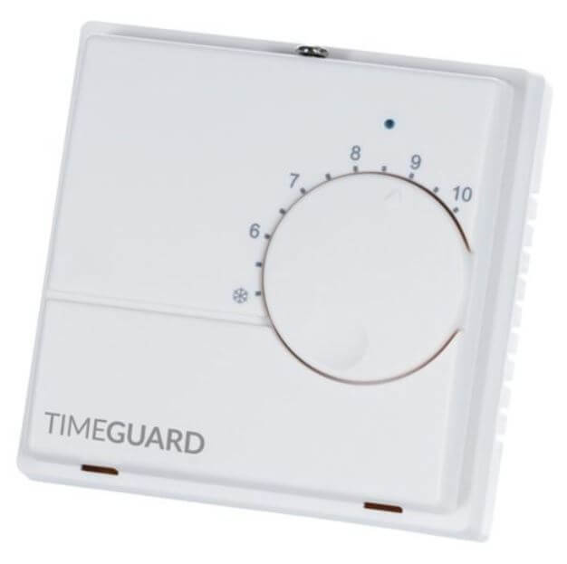
I found the mechanical frost stat to be quite inaccurate, the replacement is electronic and should therefore be reliable.
6 January 2026 – Due to the addition of Opentherm Gateway control, external frost protection had to be disconnected as only Opentherm control can bring the boiler on, therefore, I’m now relying in the boilers internal frost protection.