This blog is an update of this – Pan & Tilt Orbitron Interface post as I’ve added some pictures of the kit used and I have finally got round to putting the Rotorcards in a decent enclosure.
The main controller is a ERC-M USB kit which interfaces with the PC and programs which are running , the Rotorcard relays are controlled by the ERC-M, the Rotorcard also provides a positional feedback to the ERC-M.

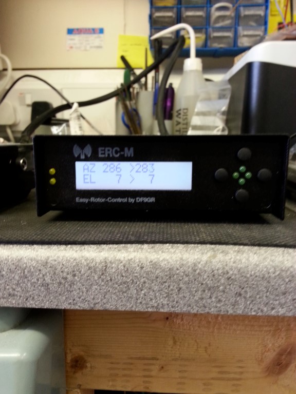
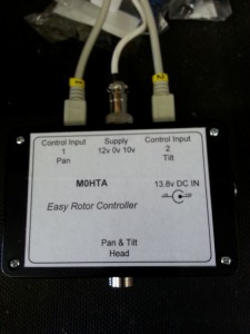
Front panel of the Desktop housing for the ERC-M, the front panel has manual buttons for up/down tilt & left/right pan, LED’s also show when a signal is sent to the Rotorcard relays.
The two yellow LEDs on the left hand side indicate the signal to the auxiliary relay.
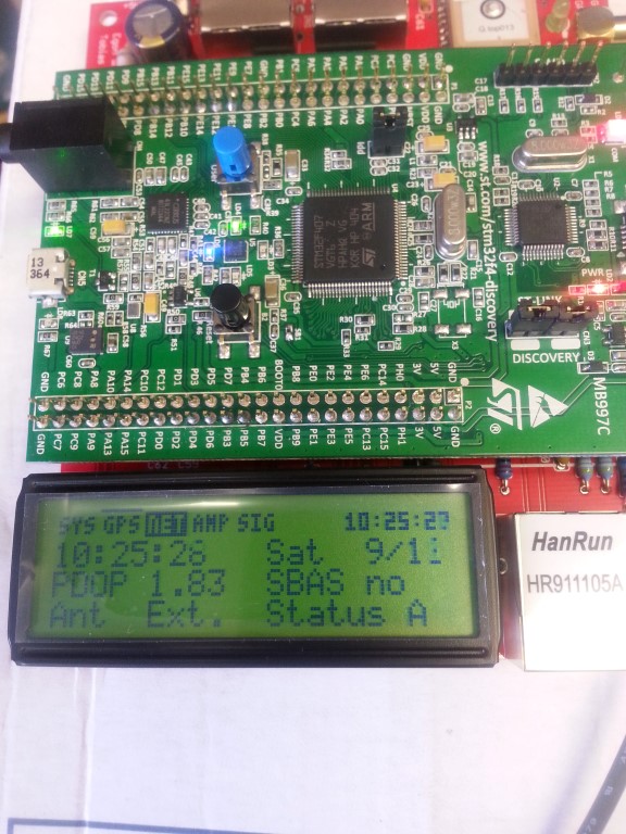
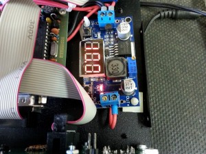
The LCD display is showing the position in degrees, the number after Az or El is the feedback from the Pan & Tilt head, the numbers on the other side of the > are the output from the software, the ERC-M compares the two values and energises the appropriate relays which in turn operate the motors in order to keep the values aligned.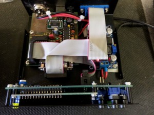
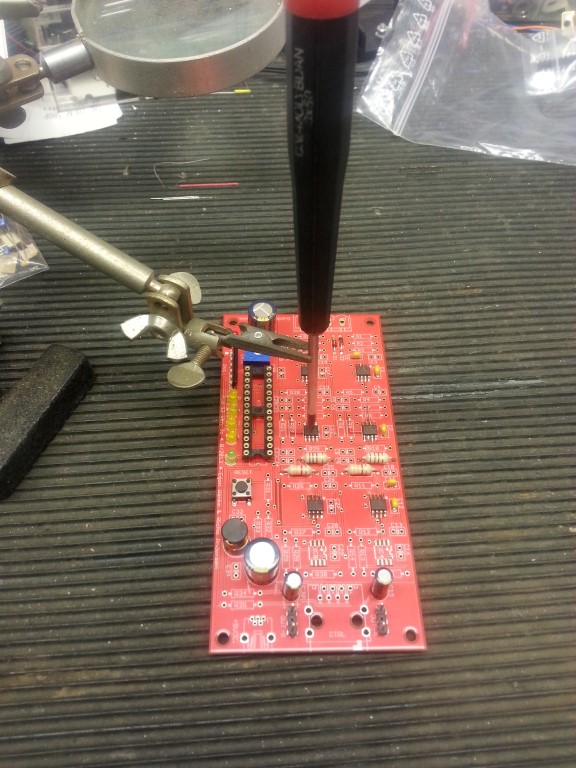
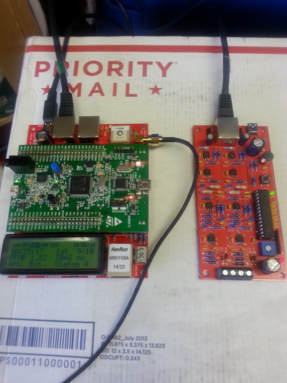
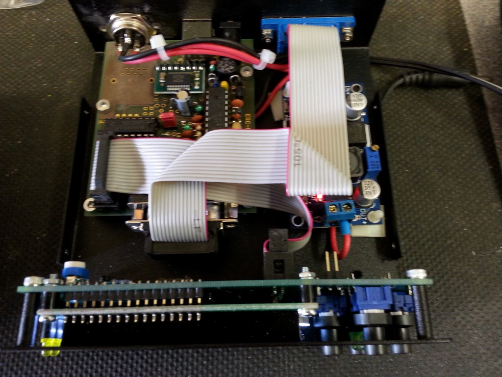
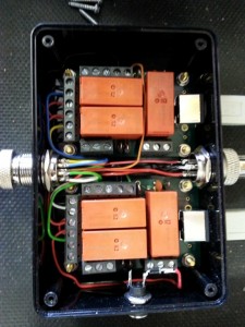
The ERC-M kit is the top left PCB, the desktop housing is also a kit comprising of the LCD display and front panel buttons.
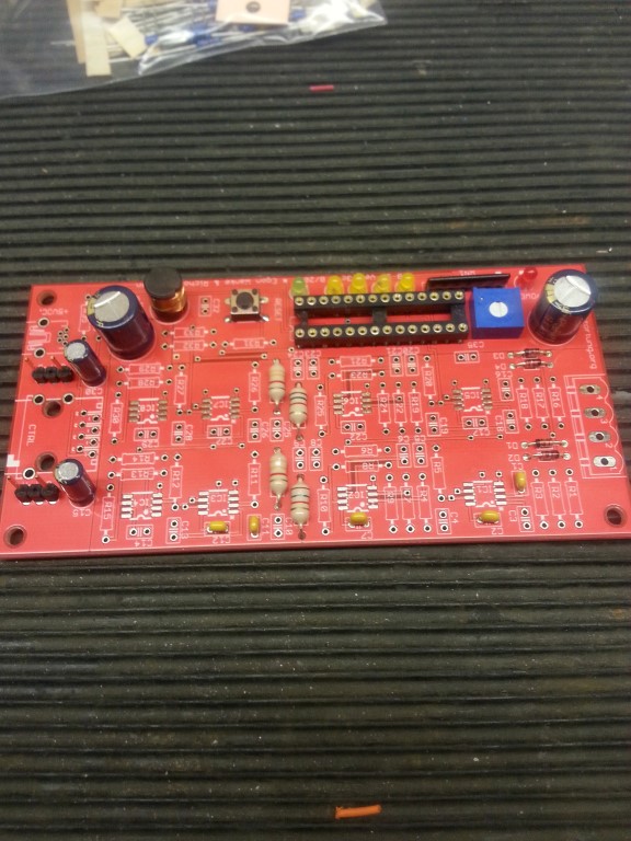
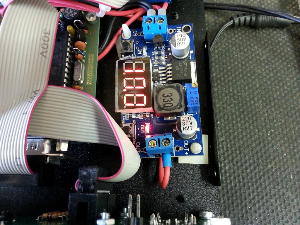
The PCB mounted inside the desktop housing is the 13.8v to 10v voltage regulator which provides a stabilized supply to the Pan & Tilt heads positional potentiometers.
An external 13.8v supply is required in order to drive the high current motors of the Pan & Tilt head.
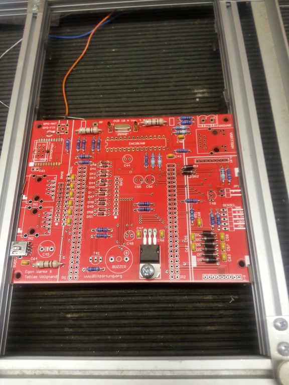
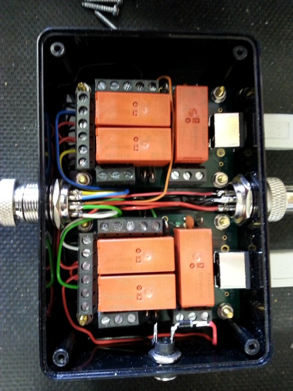
The two Rotorcards (one for Pan the other Tilt, or more correctly Azimuth and Elevation respectively) are enclosed, 13.8v can be fed to the relays here or at the desktop housing.
 The three outputs from the ERC-M enter on the right hand side to the Rotorcards, the middle connector is the 13.8v – 0v – 10v supply.
The top Rotorcard relays operate for clockwise or anticlockwise supply to the Azimuth motor, the third relay is not used (auxiliary relay) as the Pan & Tilt head does not have an electro-mechanical brake fitted, if it did, relay three would operate in advance of the motor supply relays.
The bottom Rotorcard is for elevation, Up & Down.
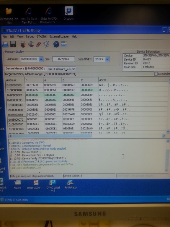
On my version, the ERC-M is connected to a PC via a USB connection to Com Port 6, the position of the heads has already been calibrated using the provided software from Easy Rotor Control.
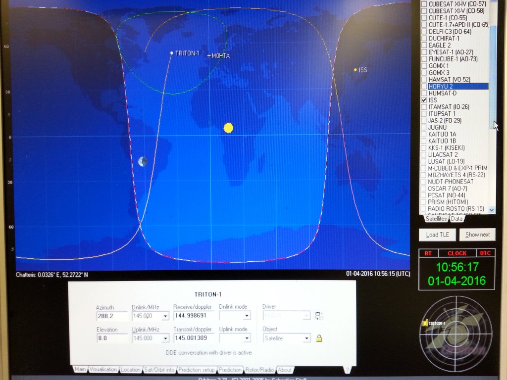
To start tracking satellites, the first step is to open Orbitron.

This is a free download program, each time it is ran, check that the TLE files have been updated then select the satellite of interest from the right hand list, once this is done, click on the satellites on screen icon.
On the bottom tabs, select rotator and click DDE a small box should now open on the screen with live positional data of the selected satellite showing, (a separate download is needed for the DDE function).
Open PST Rotator program:
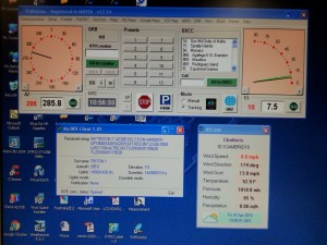
Using the PST Rotator settings configure the program to respond to Comm Port 6, use Orbitron as the controlling program, that the type of head ouput is GS-232 and Az/El is selected.
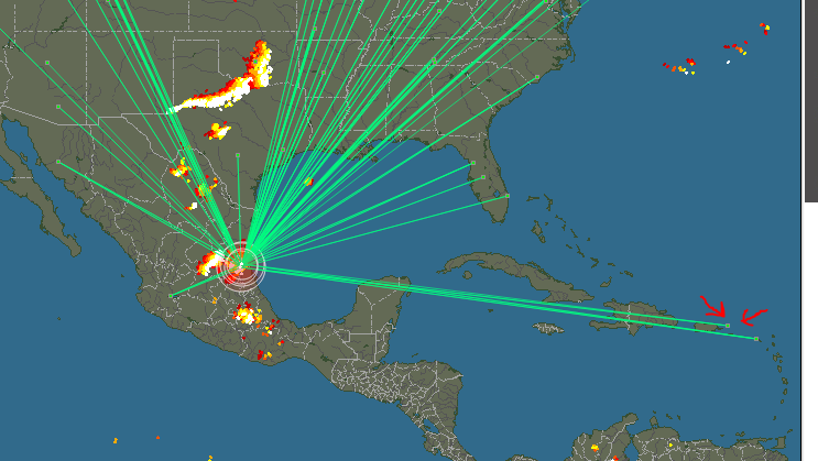
When the program is set to ‘Track’ as the above image, the displays show the actual position of the Pan & Tilt head by a black line with the green line showing where the head needs to move to, the green line is controlled via DDE from Orbitron.
A further setting I have enable is the link to weather information, this allows the mast to rotate into the wind when a trigger speed has been reached, this reduces wind loading on the mast and antenna.
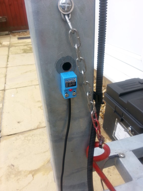
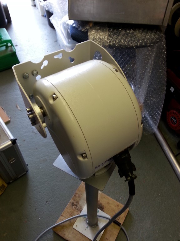
 This is a Dennard CCTV Pan & Tilt head and operates at 24v, 13.8v works it just fine with a maximum current draw of 600mA, I have commoned the potetiometers supply, so the minimum number or wire cores is 8:
2 – Pan Motor
2 – Tilt Motor
2 – 10v supply across positional potentiometers
1 – Signal feedback from Pan
1 – Signal feedback from Tilt
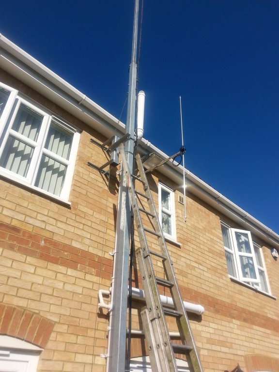
The next stage is to get some decent antennas for satellite reception.