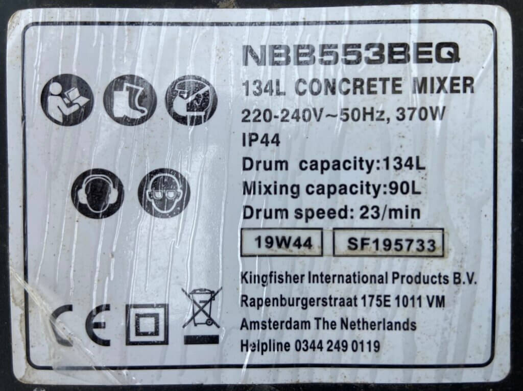
Came to use my mixer after a year in storage and everything seemed ok, the motor ran when turned on but after a few moments the motor stopped and it took a few presses of the button to get it started again.
Tipping the mixer to empty it, the mixer yet again stopped but would not restart until it was tilted back.
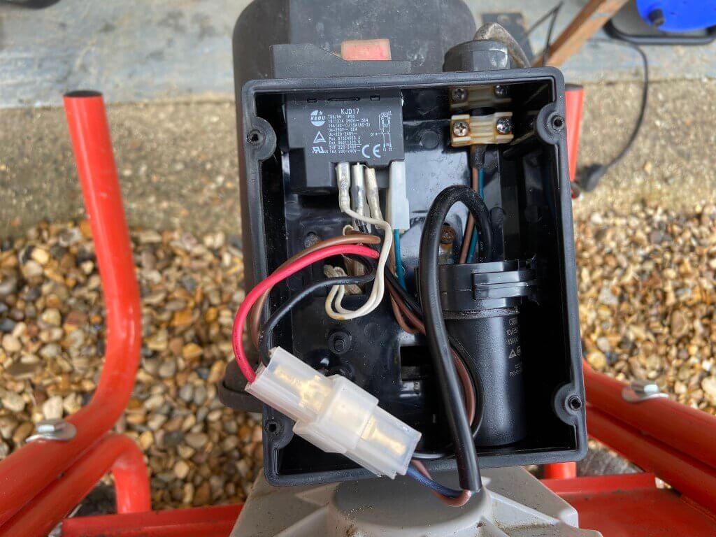
This random stopping was really frustrating, so off came the wiring enclosure cover to see if any cables have come loose, but nothing obvious other than signs of water ingress which must have happed when the mixer was in storage.
Fortunately I managed to repair it for under £10!
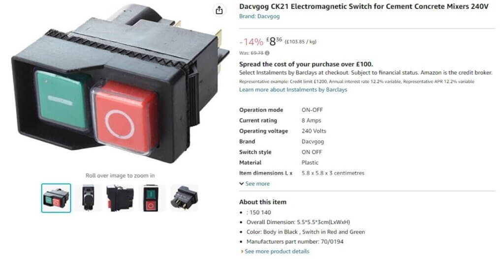
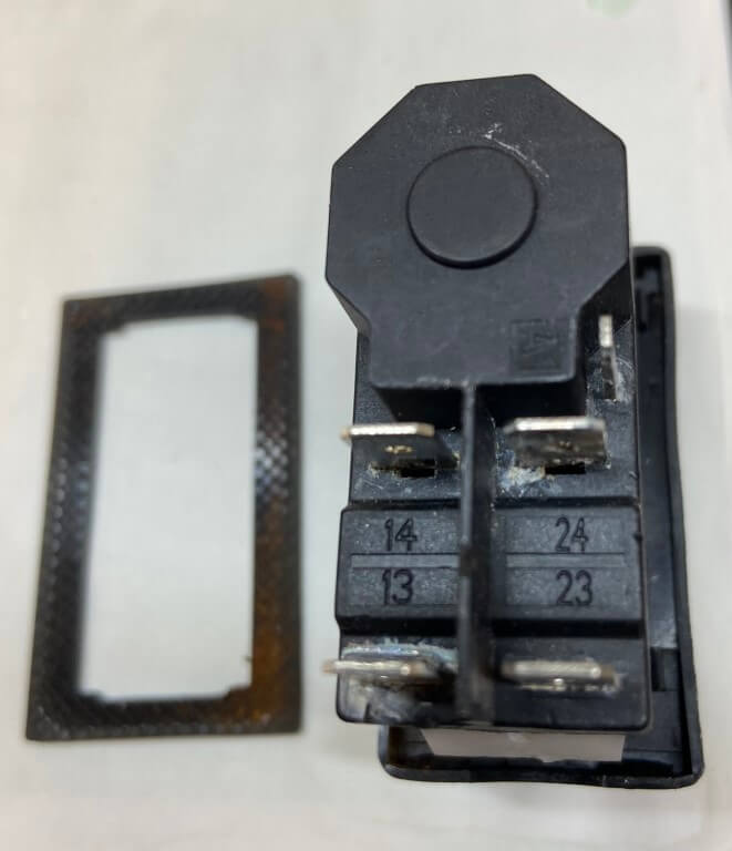
Rusted screws and slight discoloration around the switch connections, but apart from that nothing really immediately obvious as to why it keeps cutting out, so I ordered a new ‘No Volt Release’, Start/Stop module from Amazon, the one selected was a Dacvgog CK21 Electromagnetic switch for concrete cement mixers 240V:
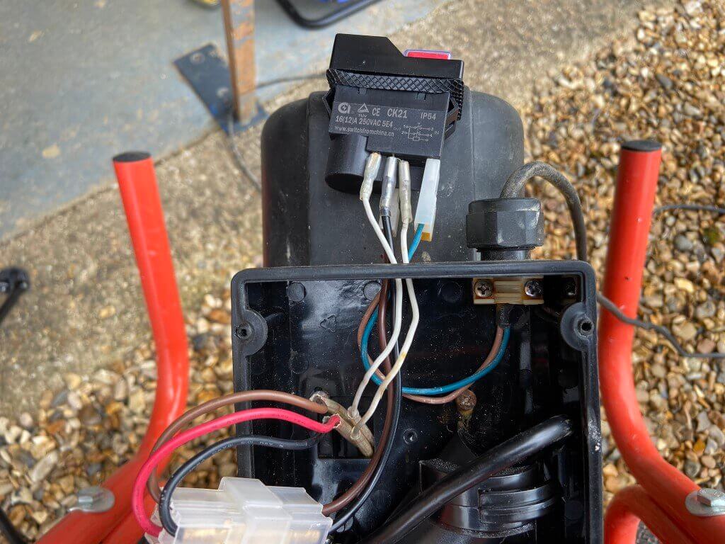
Once arrived, switch removal was very easy by depressing the internal wings on either side and popping out, I made the connections to the new switch before pushing into the hole with a reassuring click.
Power on and everything works as it should with no intermittent stopping irrespective of being tilted or not, to check it wasn’t a fault with the motors thermal fuse internal connections, I took the old starter switch apart to check its condition:
As you can see there is extensive water damage to the Start/Stop switch internally, but only minor signs on the outside, hopefully everything will be fine now 🙂
My existing, non condensing, Vaillant Thermocompact 24kW system boiler was installed when the house was built in 2002 and has worked really well, but with the price of gas its time for an upgrade.
My chosen replacement is an Ideal Vogue Max 18kW condensing system boiler with priority domestic hot water capability and 10 years manufactures warranty which I bought from Screwfix, this boiler will modulate down to 3.9kW to match my heat loss at a given temperature, whilst also giving me a short hot water cylinder recovery time when required.
NOTE – Gas and commissioning works were undertaken by Mr Fix It Gas (Gas Safe Engineer) who I would highly recommend.
Upgrade radiators in order to operate at a lower temperature flow rate,
Make wall space for relocating boiler pipework and additional expansion vessel,
Expose existing pipe connections in the garage ceiling,
Install Normally Open motorised valve for the central heating,
Rewire the wiring centre to give the boiler two switched lives, one for central heating and the other for Priority Domestic Hot Water,
Remove existing electronic water temperature control from unvented cylinder,
Reinstate unvented cylinder integral thermostat in wiring centre,
Install North Facing weather compensation sensor and wire back to boiler location,
Replace mechanical frost thermostat with electronic version and wire in,
Install new Boiler isolation switch with 3A fuse holder built in.
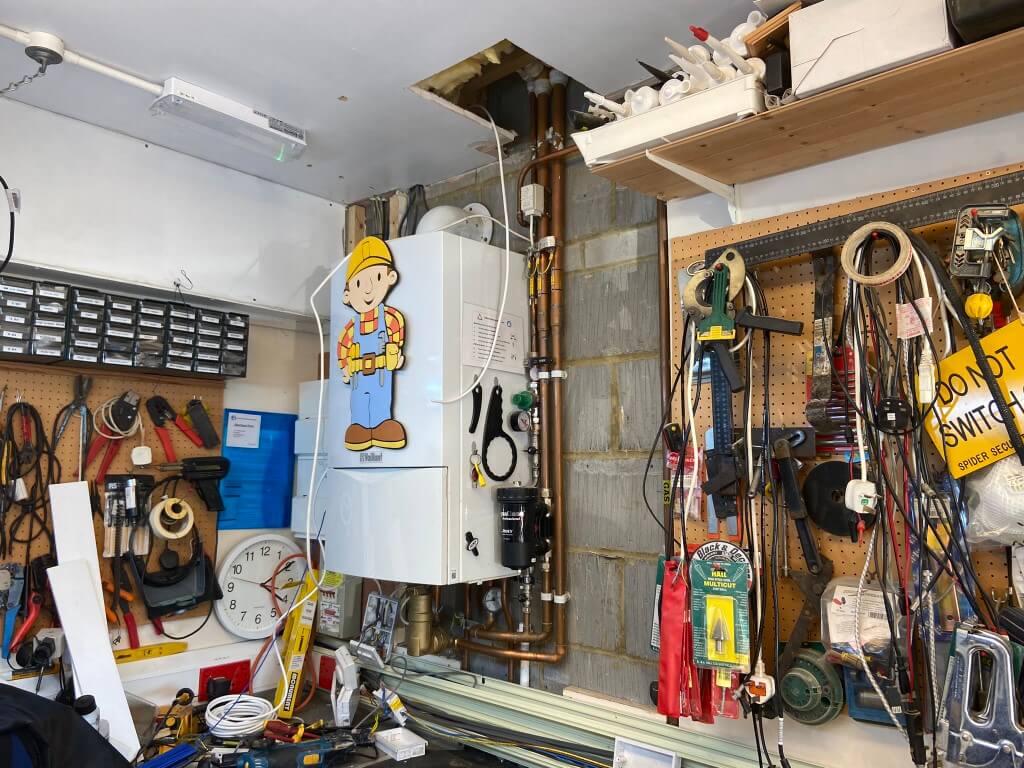
Wall space cleared around the old boiler and hole cut in the garage ceiling giving greater access to pipework, ready for the existing boiler to be removed once the gas has been capped off, the gas work was carried out on the 11 April 23 by a local Gas Safe engineer.
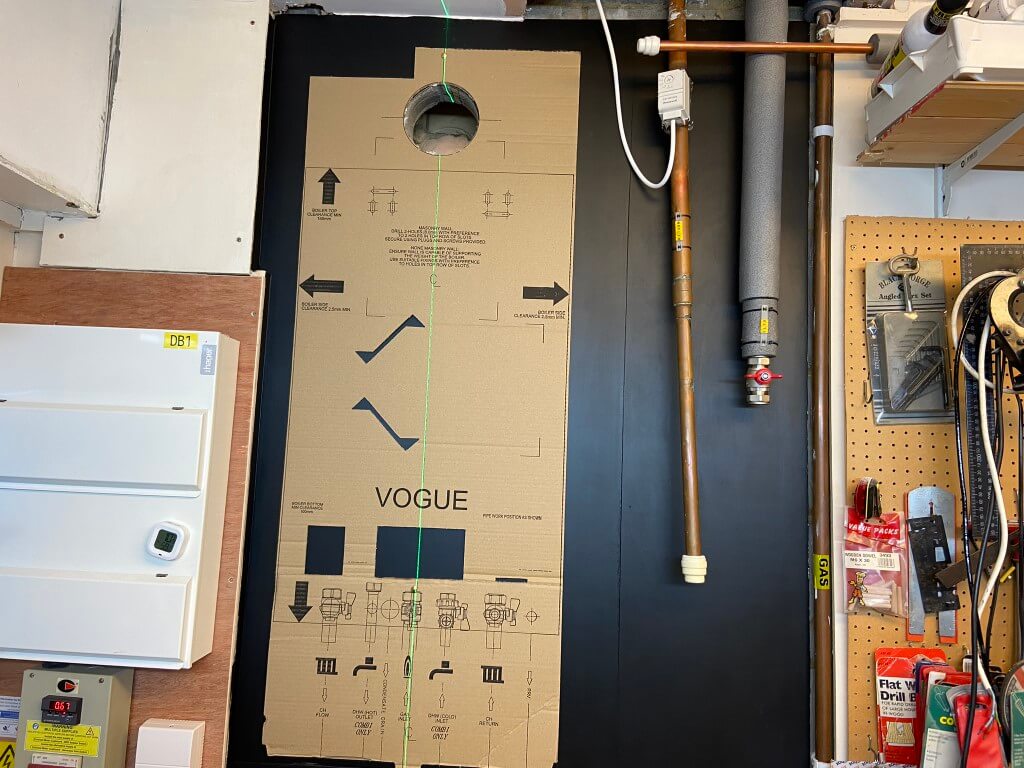
Once the gas was off by Mr Fix It Gas, power isolated and the system drained down, the boiler and flue were removed and open water pipes temporarily capped, the next job was then to line the wall with a thin ply and paint it black to neaten up the job.
As boiler comes direct from Ideal, the communications wasn’t brilliant, I was notified at 16:50 the night before delivery, fortunately this was fine for me and it arrived on the 12 April just after 2pm, I had already picked the flue up from store in preparation for the big day.
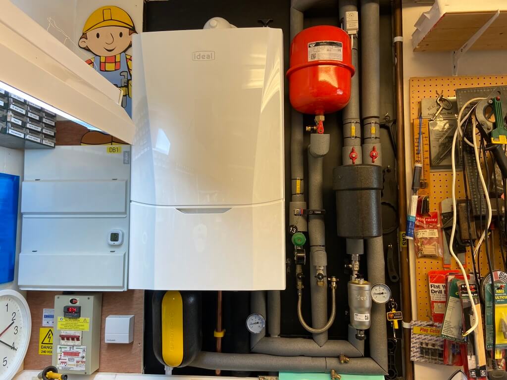
Once the new boiler arrived it was unpacked and all parts checked in case anything was missing or damaged, once happy, the new boilers template offered into position and levelled.
The boiler is hung in place and supported by a bracket, everything required for this is within the box.
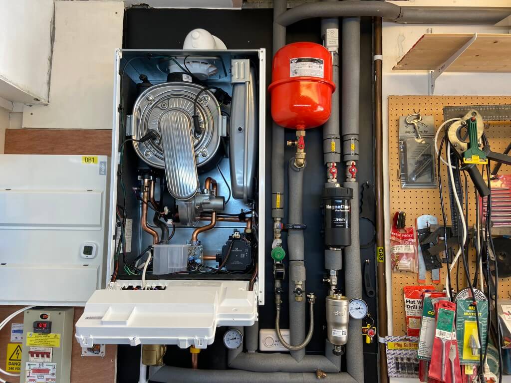
The boiler installation were straightforward with the manufactures instructions being very comprehensive, with the gas still not connected, I removed the room sealed boiler cover to access the electrical connections for the Weather Compensation sensor and the two switched lives, one for the heating and the other for priority domestic hot water.
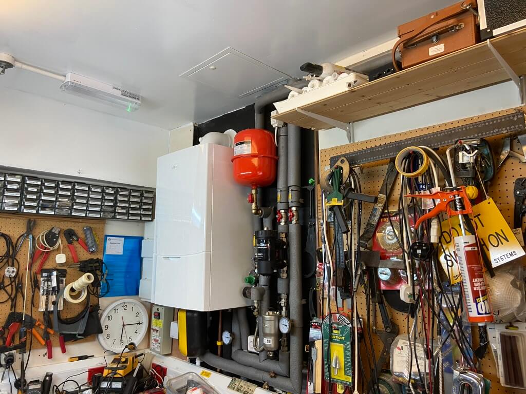
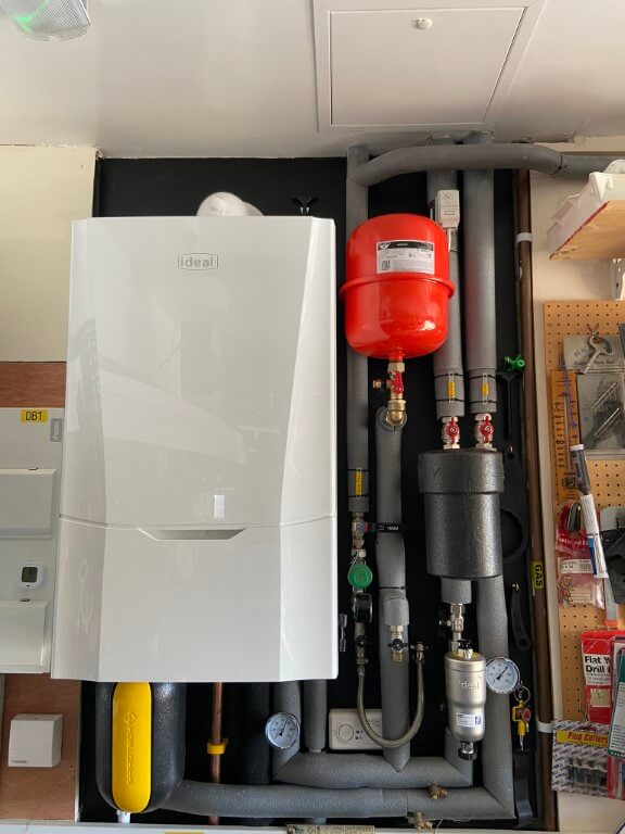
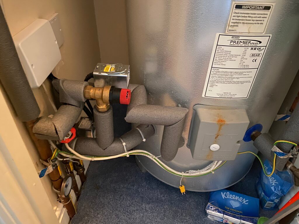
The Ideal Vogue Max comes with a magnetic filter which must be fitted to maintain the manufactures warranty, I also retained my existing Adey magnetic filter as this is perfect as a dosing pot for inhibitor addition.
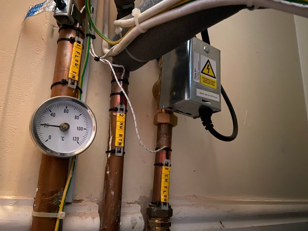
I included two dry pocket thermometers for flow and return water temperature measurement, my aim is to keep the boiler in condensing mode as much as I can.
The system was cold flushed, pressure tested and dosed with 1.5l of Fernox F1 inhibitor before the gas engineer arrived on the14 April to upgrade the gas supply from 15mm to 22mm and make the final boiler connections.
Ceiling hole closed off with a 60 minute fire resisting trap giving access to a cold water isolation valve and the completed installation was lagged using the Dr Pipe lagging pro to give me perfect cuts.
Nearly finished, just waiting for the Adey thermal jacket to arrive.
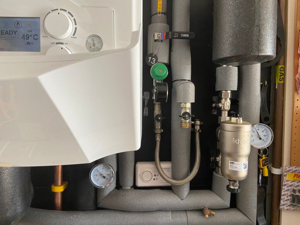
28 April 23, commissioning and Benchmark completed and registered, today will be the first time my unvented hot water cylinder is getting 800C of indirect heating at high fire of 18kW.
I haven’t yet balanced the radiators to get the greatest efficiencies, but the weather compensation is modulating the central heating water flow temperature to 49oC based on the external ambient temperature of 13oC.
The return flow temperature of 40oC, is well within the condensing range (<55oC), however, I do need to adjust my radiators to get an equal temperature differential across them all to maximise efficiencies.
Few points to note – The cold fill supply is regulated down to 1.5 bar so I can leave this connected and open without risk of over-pressurisation when bleeding radiators for maintenance.
Thermal jacket from Adey for the Magnaclean fitted, bit disappointed that Ideal do not sell an insulated jacket for their filter as it is wasting a lot thermal energy.
Last job was to test the system water quality:
pH 7-8
Hardness 60ppm (system filled with softened water)
Turbidity, base target clearly observed
Fernox Inhibitor concentration tested by titration test kit and OK
The gas engineer commented that my CO detector was in the wrong location to work effectively, ideally this should be 150mm down from the ceiling.
So, I removed the detector from the boiler back board and shifted it to where it needed to be :-), hence the two following pictures –
Radiators
The house originally had 13 Purmo panel radiators, I did upgrade one of these to a larger Stelrad K2 type as the bedroom over the garage was undersized a few years ago.
The Heat Loss calculations linked earlier, determined that a total of 9 radiators would needed upsizing to meet the heat losses at the lower radiator flow temperatures of DT30 to keep the boiler in the condensing range as much as possible.
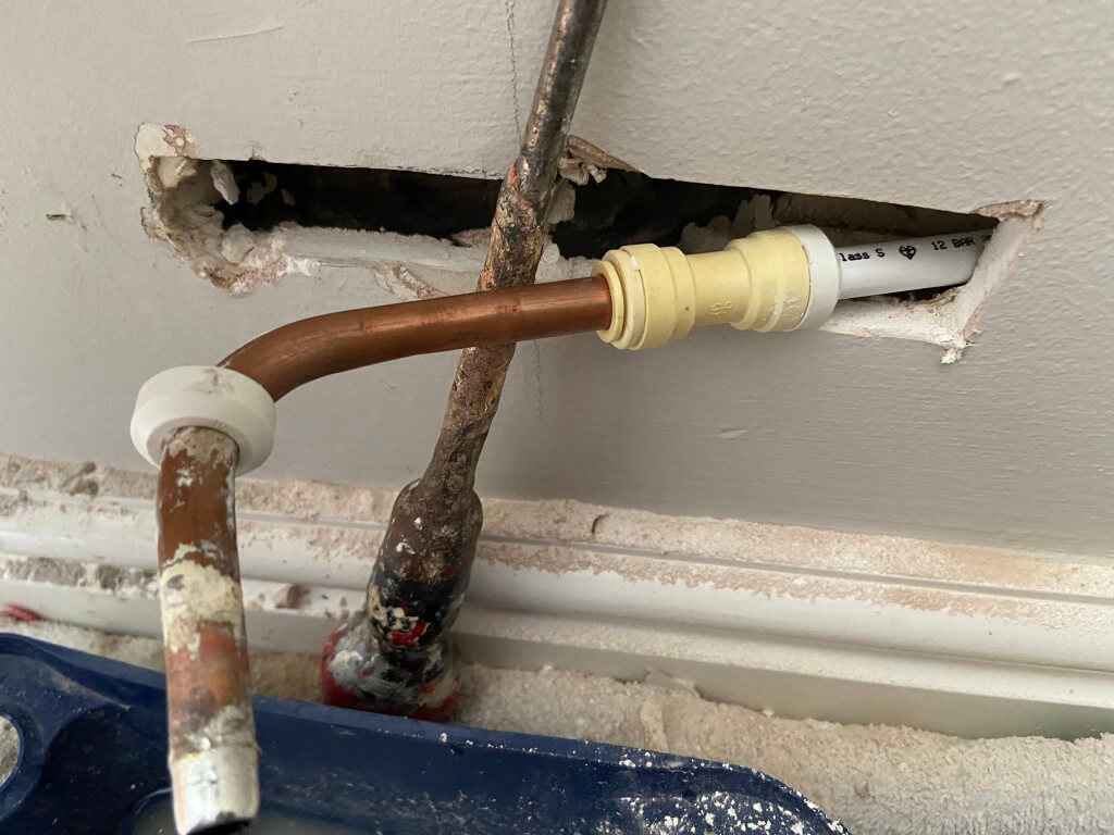
The pipework to the radiators is a combination of 10mm plastic pipe behind the dot and dab plasterboard walls, transitioning to 10mm copper pipe for the final connection to the radiators, fortunately all the downstairs radiator lock shield valves have inbuilt drain off valves, making removal and replacement of the radiators a lot easier.
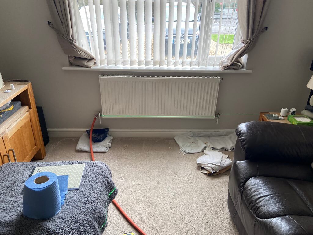
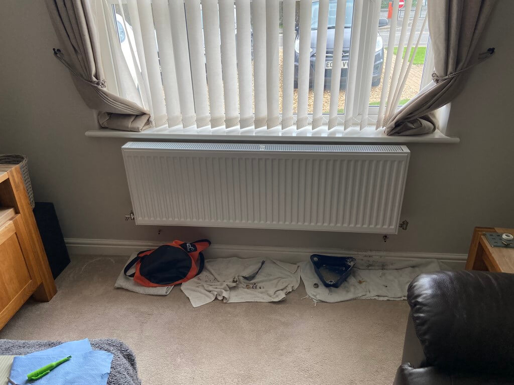
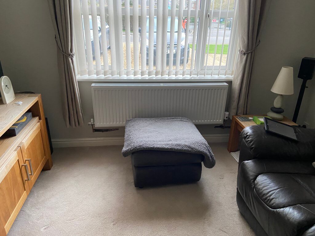
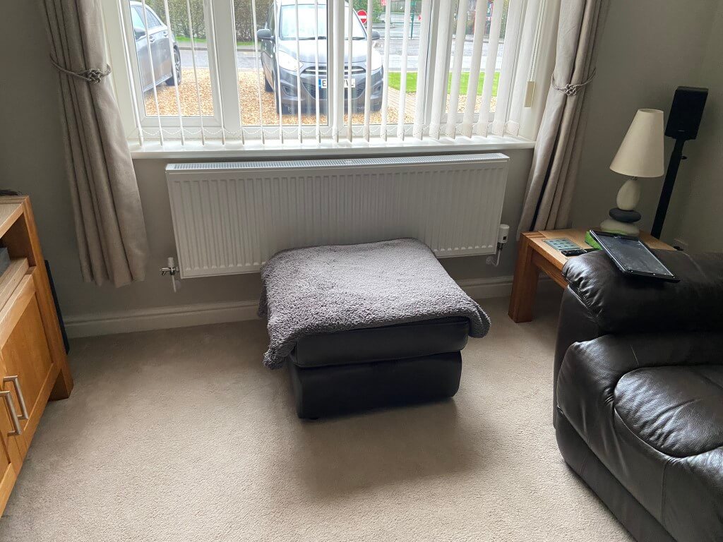
Lounge radiator draining down with the laser setup to project a line through the centre of the radiator tails.
Radiator removed, I used Plumb Tubs and a 20l foldable bucket to catch any drips, before lifting the radiator off its brackets, I fitted Plumb Thumbs to avoid any dirty water getting on the carpet.
New radiator mounted with insulated foil reflector behind it to try and conserve useful heat. Using the laser level line previously set up, I marked up 20mm from this which is to the bottom of the mounting brackets, I used a combination of Grip It (Brown) and Corefix fixings as this is a heavy radiator at 37 Kg.
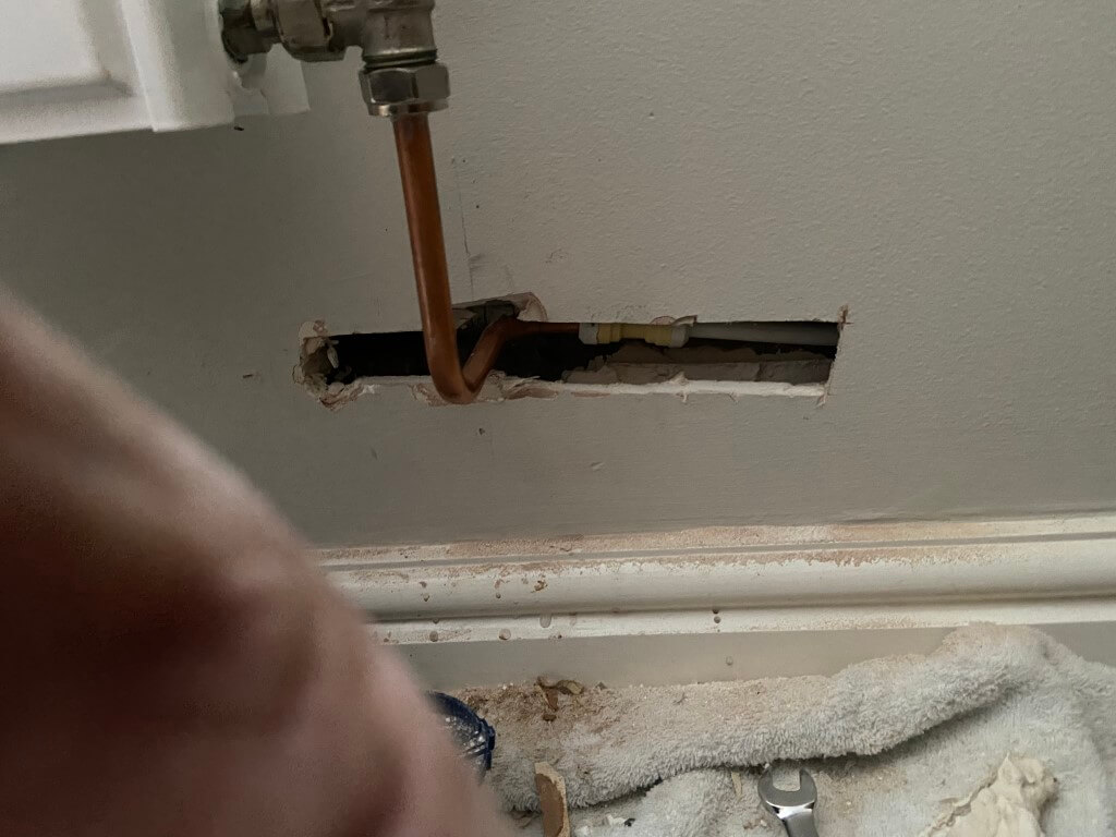
As you can see the pipework will need adjusting to get the bend back where the vertical pencil line is.
Using a Multitool I exposed more of the pipework back to the plastic/copper coupling, but needed to cut the wall back even further so I could get the correct positioning in line with the pencil mark.
The coupling come off the pipes by prizing the white end cap of and then pushing the collet towards the fitting, (I used a 10mm open ended spanner for this), and at the same time pull on the pipe.
I needed to shorten the plastic pipe, so I used pipe shears to give me a neat edge, then I used a 10mm plastic pipe insert from Screwfix, before reassembly.
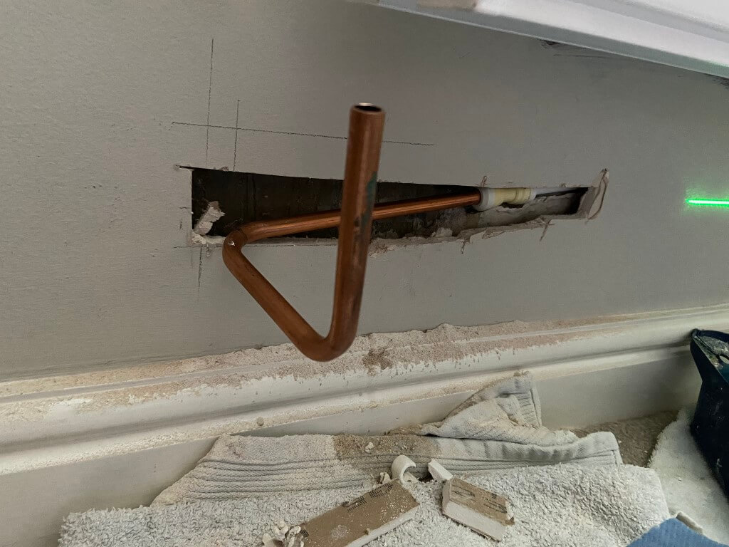
Using 10mm copper pipe and a pipe bender, I formed the pipe to the radiator.
The other side of the radiator only needed the copper pipe extending although it was a longer wall chase.
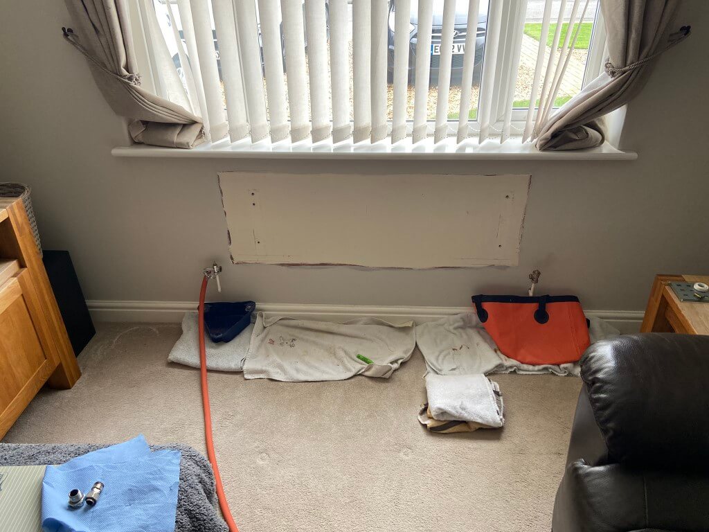
Radiator all piped up and tested for leaks, now ready for hole filling.
Over the exposed pipes in the wall I used a foiled bubble wrap before applying a plaster bonding coat, once gone off I used a white filler and flattened this to a smooth surface.
A few coats of sealer, then paint and a new collars at each end, and the job was done.
External Sensor
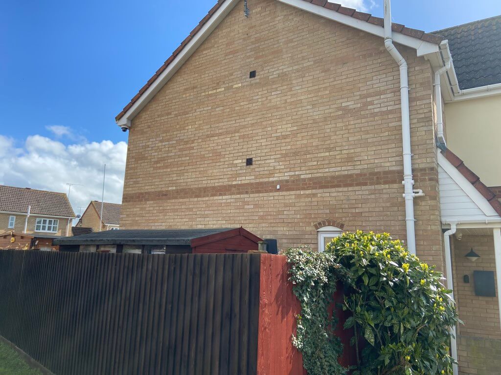
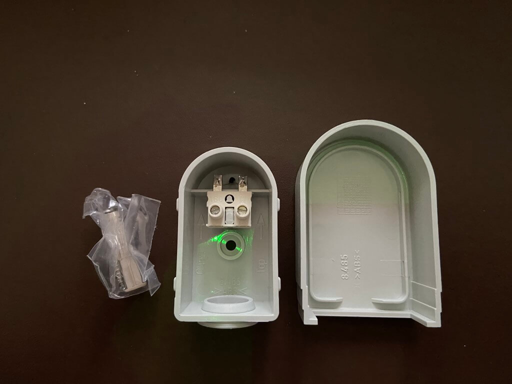
I bought the Ideal OS2 weather compensation sensor off eBay, fitting was straightforward on the external North Face of the house at a height equal to that of the upstairs floor.
Only two 0.75mm2 wires are needed back to the boiler from the sensor for direct connection within the boiler.
Airing Cupboard Works
This is the location of my unvented cylinder and two existing normally closed motorised valves as I have a ‘S’ Plan system which needed modification into an X Plan.
First job was the removal of my ESi electronic hot water cylinder temperature control unit which I blogged the installation of HERE, with all power isolated, the cabling was removed from the wiring centre.
After removal of the ESi unit I blanked the 20mm hole with a plug.
While the wiring centre was open and power off, I replaced the Normally Closed central heating motorised valve with a Normally Open version, this modification is required to enable the priority domestic hot water to operate.
The wiring was then modified so that when Hot Water is called for, a switched live from the Hive Receiver operates both motorised valves at the same time, the live wire to the motors is in series with the unvented cylinders thermostat so that when the cylinders water is at the correct temperature, or there is and overtemperature, the thermostat will open, removing the live connection to the motors.
This will cause both motorised valves to return to their default state of Central Heating – OPEN, Hot Water – CLOSED.
In normal operation for hot water, the motorised valve will open and in so doing switch a live feed to S2 on the boiler, triggering a higher output water temperature.
Had a fantastic few days in Iceland courtesy of Lucy for a Christmas present and saw what we went went for, which was a spectacular display of Northern Lights.
I bought a Flowzone Cyclone 2.5 battery pack sprayer and I love it, however I did experience a battery issue and the company were superb in sending out a replacement.
The issue I experienced was that the battery power level only indicated a red flashing LED after being on charge overnight, the battery test is operated by pressing the orange battery symbol and all green LEDs should illuminate after changing.
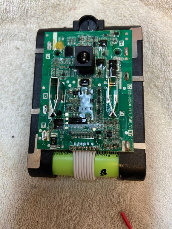
I did offer to send the faulty battery back to the supplier but they were happy for me to dispose of it, so I thought I’d open it up to see what’s inside.
A T10 x 50mm Torx security screwdriver was perfect to remove the four securing screws, the screws aren’t security ones, but it was the only one I had in the right size.
A cool feature of the battery is that the low voltage charging transformer lead plugs directly into the rear of the battery, no external charger is needed.
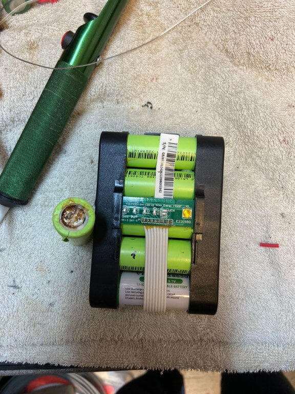
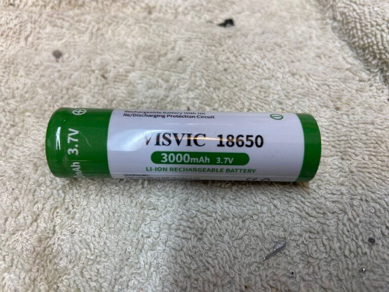
The battery pack contains 5 li-ion rechargeable 3.7v type 18650 batteries, once charged the voltage per battery is 4v, testing each battery in turn, it soon became obvious which one had failed as its voltage was 0.37v and the end cap showed signs of discolouration, not sure what caused this, maybe the battery compartment door wasn’t double clicked closed and water got in, I don’t know, but I’m very careful to make sure everything is dry by the battery just in case.
Above picture shows removed dead battery and the new one in-situ, battery cell replacement was quite difficult as the cell connections were spot welded on, and cells were interconnected, fortunately it was the end cell that needed changing so I peeled off the spot welded tab and unsoldered the tab connections on the PCB and this gave me enough room to get the old one out and the new one in.
Once the new battery was in I used some liquid flux, tinned the tabs and cell connections to make the heat contact on the battery as quick as possible using my Weller 100w soldering gun.
Everything works which is a result, also I have 5 battery’s left over as I had to buy 3 lots of 2, pity they don’t sell them individually they cost £20.62 but I do now have a spare, so can’t complain 🙂
When I installed my Pyronix Euro46 house alarm, the garage was designed as a separate area allowing it to be set independently of other areas, to confirm final setting and to start the entry timer, a small lever microswitch was fitted to the sliding locking mechanism on the garage door.
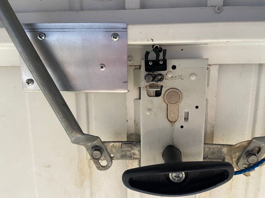
Microswitch to detect lock position
When the door is locked, the pin is over to the right; the picture above shows the door in the unlocked state.
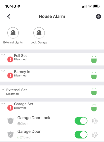
This arrangement works really well, the biggest problem is when I come to set the alarm from within the house, only for the alarm to indicate that I had forgotten to lock the garage door, meaning I have to go outside to the front of the house and lock the door, a real niggle 🙂
The image shows that the garage door is not locked, but now pressing the Lock Garage Icon will do this for me.
Locking Process
This is in two parts, the first being how the mechanically lock the garage door and the other is how electrically this would work with the alarm system.
The garage door can be locked with a key from the outside or by sliding the internal locking pin to the right, sliding the pin takes quite a force to manually move, so I took a punt and bought a 12v Micro Linear Actuator from Amazon, this has a 30mm stroke and can apply a force of 60N (6kg) and turned out to be ideal.
I mounted the actuator on a small sheet of 1.5mm aluminum and with the actuator fully extended, aligned the end of the arm to the full throw of the locking pin and tested operation with a battery, once happy, I used self tapping screws and affixed the aluminum to the garage door cross member.
The wires from the actuator and microswitch are taken off the door by a flexible door loop.
The triggering of the actuator was the next part to look at.
The actuator has an inbuilt limit switch, stopping the motor at each end of the arms travel, to operate, apply 12vDC and this will extend the actuators arm, reversing the 12v polarity will causes the actuator arm to retract and stop.
I could have physically connected the actuator arm to the locking pin enabling me to both lock and unlock the door electrically, the only problem with this is that the external euro lock would no longer work, as the locking pin would be held in position by the actuator arm which cannot be manually retracted.
Actuator Logic
The garage door to automatically lock when setting the alarm,
Ability manually trigger the locking actuator from the ProControl+ App on my phone,
If the door is locked the actuator has no need to operate.
Programming Euro46
The Pyronix Euro46 has a comprehensive number of programmable outputs and options which made the actuator logic easy to setup via the ‘InSite’ software.
The garage has a PSU/ZEM8 which has 4 programable outputs, I used two of these Outputs for this project, Outputs 2 & 3.
Output 2 was programmed to ‘Follow’ (Output type 35) the switch state of the lock microswitch (Input 33), if the lock is closed, the Output would go LOW enabling Relay 1 to energize, the contacts of this relay apply or remove a 12v positive to the trigger of Relay 2.
Output 3 was programmed as ‘Gate’, the gate is comprised of a combined OR logic within the panels software.
Output 3 would go LOW enabling Relay 2 to energize if the positive from Relay 1 was available.
Output 3 LOW conditions-
if the Exit time starts for Area ‘D’ (Output type 280),
OR
the Apps virtual Output is triggered (Output 0171 timed for 8 seconds).
Relay 2 simply changes the polarity of the 12vDC to the actuator, in the relays OFF state, 12v is applied to retract the arm, in the ON state the arm extends, once Relay 1 operates, Relay 2 will drop out causing the arm to retract.
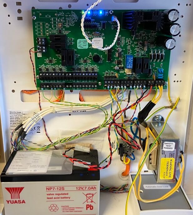
All connected up with the door lock relays housed within the PSU/ZEM8 enclosure, 12v supply to the actuator is fed from the PSU and further fused down to 1A.
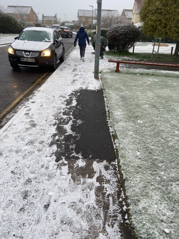
Overnight we had the first light dusting of snow and as normal we took the dog for his morning walk, when we got outside my house I noticed something odd had happened to the pavement.
Now it didn’t take a genius to work out that something is getting warm under the pavement and melting the snow, and it looks like, at some point in time, that the area had been dug up before for some reason.
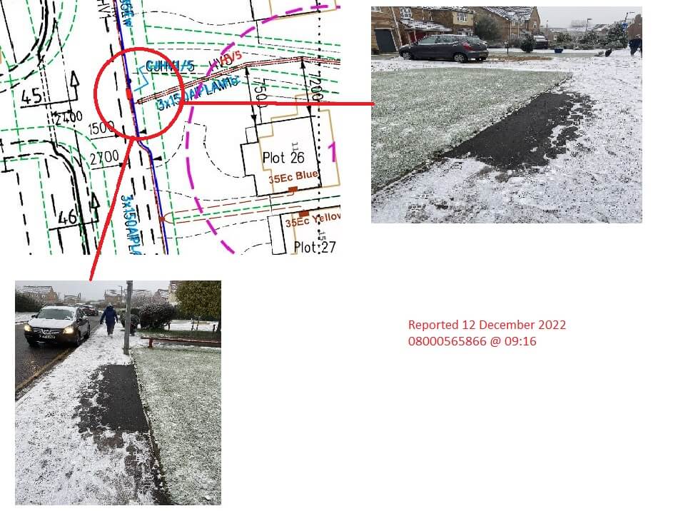
Having way too much time on my hands, I looked at electrical cable plans for my estate, and their it was, a significant cable joint:
Checking online, the network maintainer is UK Power Networks, telephone 0800 056 5866.
I gave them a quick call to let them know of the issue, the representative said they would send someone out to check it.
Why is it important to report this?
The simple answer is if the cable joint fails, it could be a catastrophic failure with the potential to cause harm or damage, or on a more basic level, result in a power outage until the joint is excavated and repaired.
Both can be avoided by early intervention, as an aside, I’ve noticed quite a few cable joints failing and my presumption is that this is due to the increase in Electric Vehicle charging and this will only be exacerbated by the colder weather as more and more heaters get switched on, (if we can afford it!!).
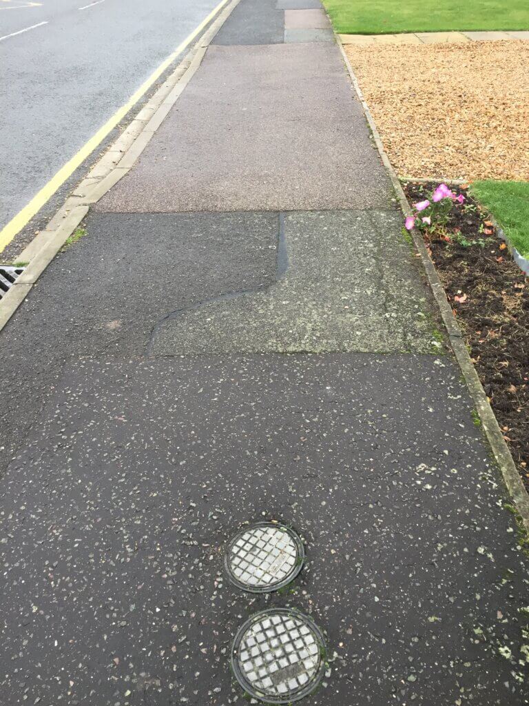
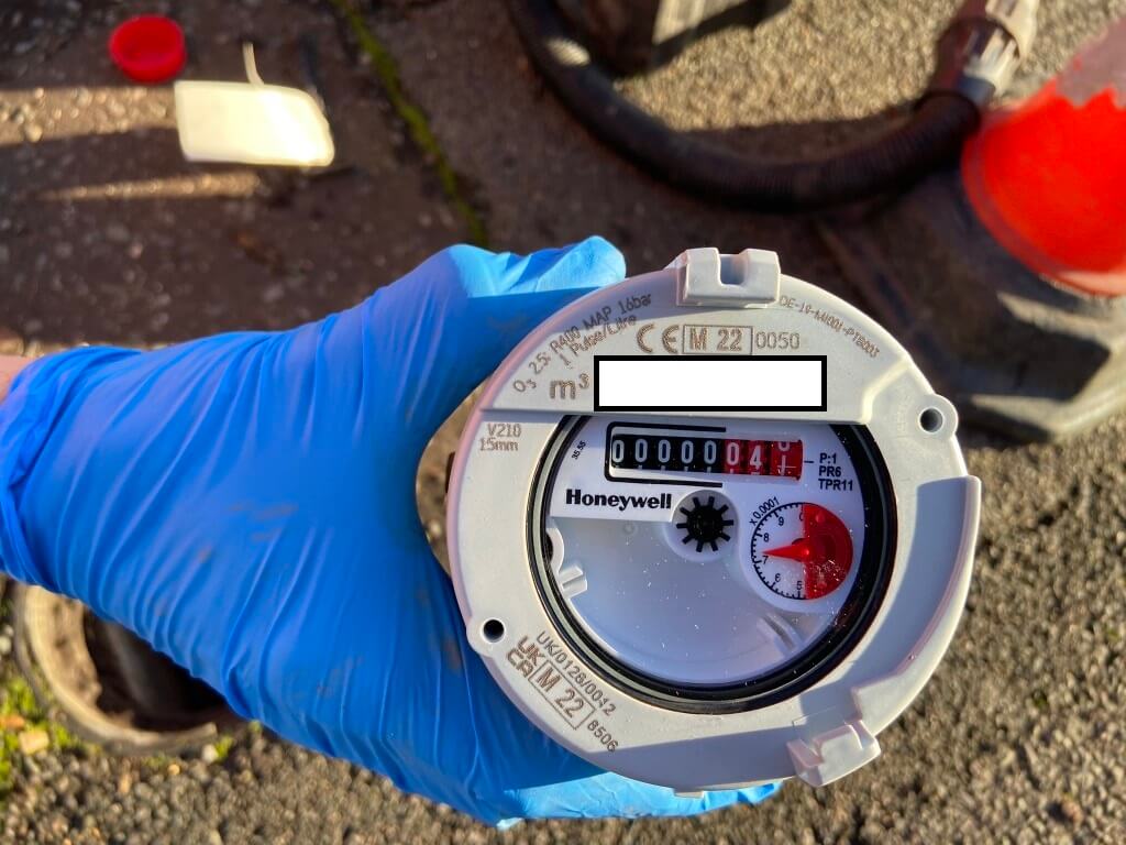
Every time I replace the salt blocks in my water softener, I note the reading on the water meter and log it, typically after 26 days I use between 8 to 9 m3 of water, however, when I checked on the 1st December, I had only used 1.6m3, so something was wrong with the meter in the street.
Two meter covers, the lower one is to my property.
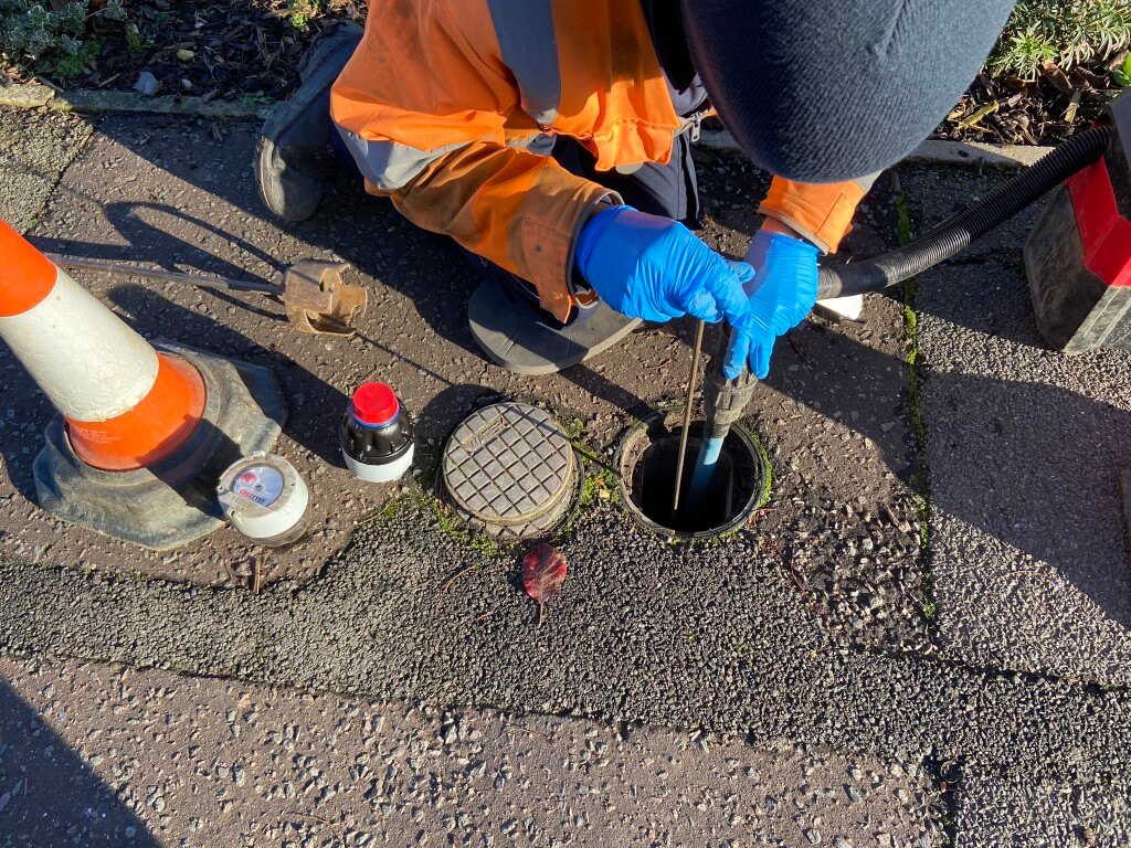
After reporting the low reading to Anglian Water on the 1st December, Jonathan the engineer called on the 7th December to replace the meter, I assumed that the meter would need to be dug up and replaced, but when I was told it will take 5 minutes, I thought I’d take a few pictures.
His first job was to insert a special key into the upstream isolating valve, and turned the water off feeding the meter, he then used the tool in the picture to slide over the meter body and simply unscrew it from the fixed base.
With the meter removed, he cracked open the isolating valve and using a wet vac, flushed out the meter body with fresh water incase their was any debris which could damage the new meter.
Once the flushing was complete, the new meter with the red protective thread cap removed was screwed into place and the water deisolated.
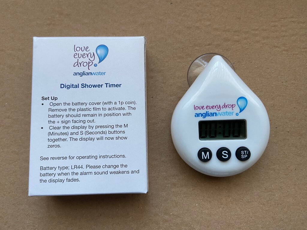
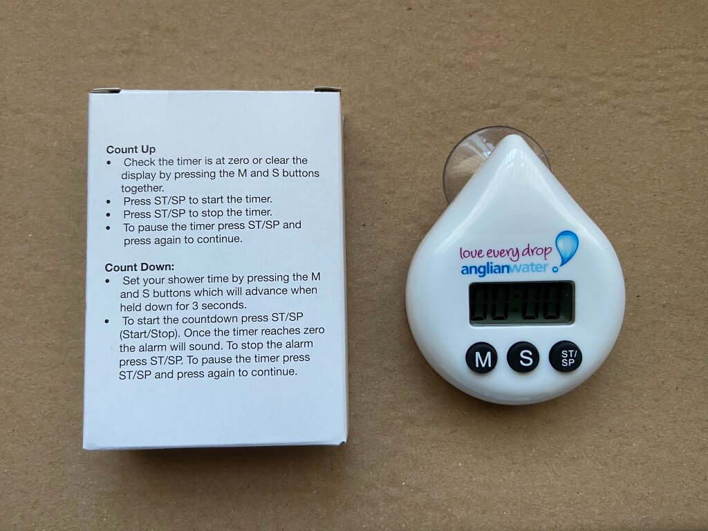
I was asked to test that the water was now working in the house, which it was, and he left after checking for meter leaks, but not before giving me a water saving pack which was much appreciated, especially the gadget to set your shower target duration in order to preserve water.
I have to note that with every interaction with Anglian Water, I have always found them to be professional and courteous.
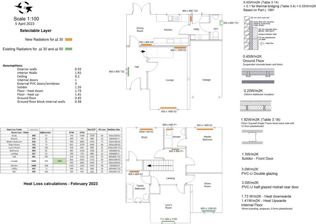
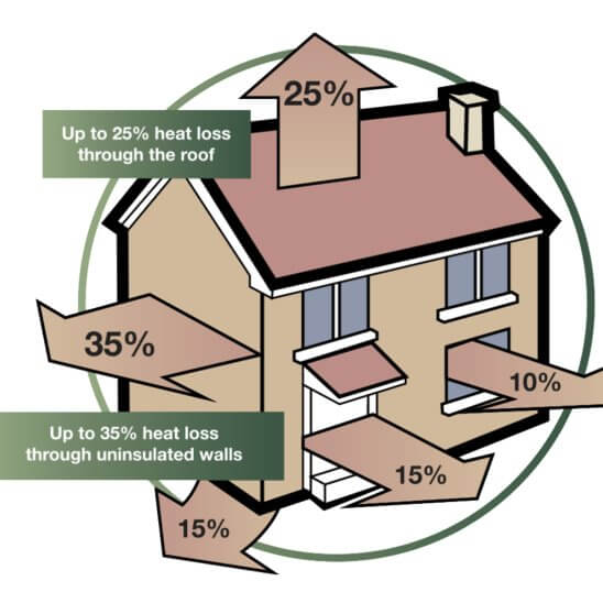
My existing Vaillant central heating system boiler has been installed since 2003 and performs very well, however, when it is time to upgrade, I want to make sure the boiler and radiators have been correctly sized for a central heating design flow temperature of 550C (Δ t30), this flow temperature will be in compliance with Part L of the Building Regulations 2021.
For context, my existing system boiler is on a Honeywell ‘S’ plan, meaning I have two independently controlled motorised valves, one directs the boilers heated water to the radiators, whilst the other valve supplies the same temperature water to the unvented hot water cylinders indirect heating coil.
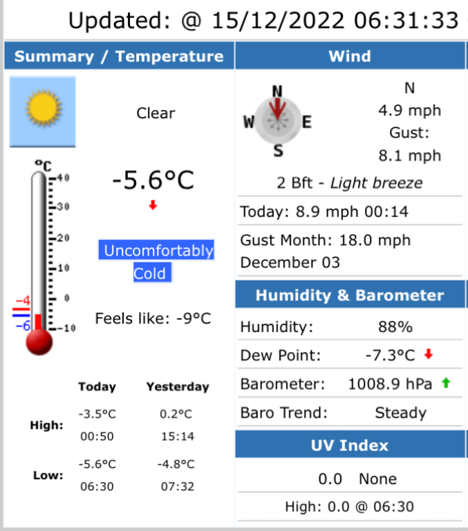
I have used recommended design temperatures for each room, this varies based on the function of the room and as I’m located in East Anglia, my CIBSE design outside temperature is -3oC.
Although the calculated heat loss minimum is -3c, as you can see, it does get colder.
So, my CIBSE Lounge design temperature is 21oC at an outside temperature of -3oC, therefore, my differential temperature is 24oC, meaning I can heat my room to 21oC, overcoming losses, even when its -3 oC outside.
Why Bother!
Good question.
Radiators are designed to give out a certain amount of heat (measured in Watts), when the water flow temperature in to the radiator is 75oC and the exit water temperature of the water from the radiator is 65oC, so 10oC has been dropped across the radiator.
For ease, lets say the water temperature across the radiator is in the middle of 75oC & 65oC making it 70oC, if the room is at 20oC, then 70oC – 20oC = 50oC, this is the Delta Temperature or Δ t50.
So what! Well at Δ t50 my bedroom radiator for example, gives out 1106 Watts, if my flow temperature is reduced to 55oC or Δ t30 then the same radiator will only give out 563 Watts of heat energy and as my bedroom needs 885 Watts to keep me warm, I won’t be a happy bunny.
The heat loss process proves if your existing radiators are adequate or not at reduced flow temperatures for each specific room in the house.
Heat Loss Process
Firstly I’m not a heat loss expert, this is an amateur blog on how I did mine as accurately* as I could, if you spot an error, please let me know as I’m always learning.
*Note- I have made a number of assumptions as I’m unsure of how the ground floor was constructed for example, however, I have used the 1991 version of Part L as my guide, as this was the current version when the house was constructed.
The key document for heating system design including calculation losses is the CIBSE, HVDH Domestic heating design guide (2021) which is downloadable for a fee (was £20).
The CIBSE guide includes recommended design temperatures based on the use of the room, for example a lounge temperature is 21oC also in the guide is common building materials and constructing type heat losses.
I also downloaded a free Heat Loss Excel Workbook from MCS and guidance on U-Values for the workbook are HERE.
The MCS Excel workbook requires detailed room, by room information to be gathered, including floor, ceiling and wall construction, I found the workbook to be excellent and well worth the effort of completing.
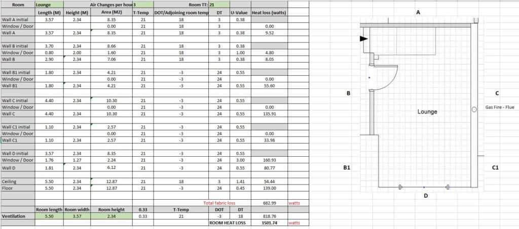
I decided to create my own spreadsheet so I can tailor it to take into account wall types changing on the same wall.
In the lounge for example wall ‘B’ separates the Hall and the wall is made from lightweight block, whilst wall ‘B1’ is an outside wall made from different materials with different thermal losses.
Using the spreadsheet, the lounge heat loss is calculated at 1502 Watts, this is quite high due to the gas fires flue increasing ventilation losses, however, my existing radiators give out 1973 Watts, so all is good.
With a new boiler at a flow temperature of 55oC, the outputs will be 997 Watts, not so good!
I did the same process for all the rooms using the drawing below.
Using Visio, I drew a scaled drawing and transferred all the measurements, this made the heat loss process easier as I could tick off the different materials and where they were used, ironically the MCS spreadsheet came out with very similar numbers to my spreadsheet, even though I drilled right down in to part-wall construction and factored heat gain/loss to adjacent rooms.
What was the outcome.
I learned that the total heat losses for my property is just under 6.8kW and I have a 24kW boiler which does not have the ability to modulate the gas valve, so when it fires up, I get 24kW of heat output whether I need it or not.
I do however need a minimum of 17.3kW to heat 170 litres of water in my unvented hot water cylinder, this means my new boiler will need an output of 18kW to heat my volume of water in 30 minutes.
Of the 13 radiators, I will need to increase in size 9 of them to compensate for the lower flow temperature, also I will need to factor a larger expansion vessel (12 litres), due to the increased heating system water volume as a result of the larger capacity radiators.
This exercise enabled me to have an informed boiler wish list:
System Boiler to have an output of 18kW,
Boiler to have Domestic Priority Hot Water,
Boiler to have an acceptable low kW gas modulation,
Boiler to modulate flow temperature on weather compensation.
Armed with this information, I can start to swop out existing radiators and make plumbing additions ready for a gas safe engineer to change to boiler, my pre-works will save him/her time and me money.
Update 5 April 2023
Required radiators have been updated, I chose Stelrad radiators as they are a well know and trusted brand, the only radiator which wasn’t Stelrad was for the Utility as they don’t do the size of 400 x 900 Type 22 (K2), so Kartell K.Rad was used.
I have always sharpened my lawn mower blade with a wet wheel grinding stone but the problem was getting an accurate cutting angle on the blade, looking around for a better solution, I came across the All American Sharpener which looked perfect.
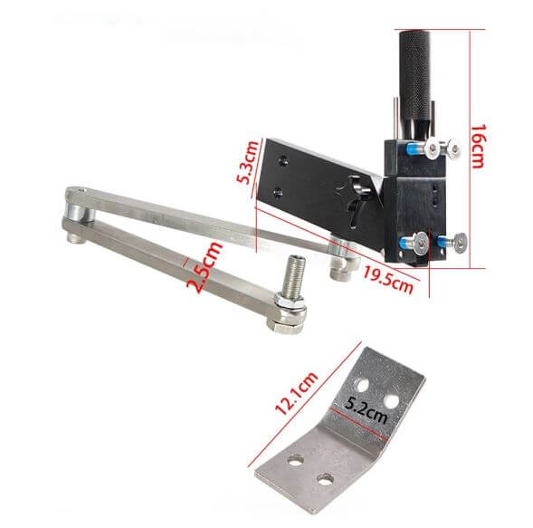
The appeal of this sharpener was the repeatability/accuracy of the blade grinding process and the fact that it makes use of an angle grinder that most DIYs already have.
The bad news is the cost, the current price on Amazon in the UK is £416.75 (2nd Nov 22) for a genuine All American Sharpener.
Being well outside my budget for an amateur, I went straight to eBay and for £56.97, bought a Model 5005 product which looked like it was based on the genuine version of the tool, however, its design was not simply not functional and I returned it for a refund.
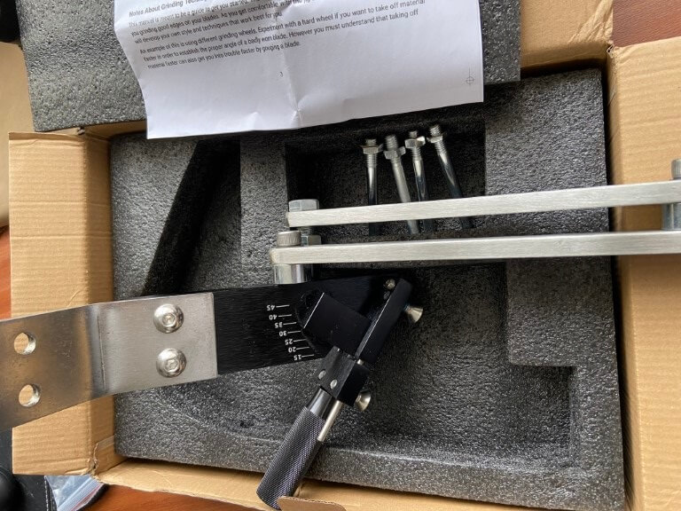
I ordered this on the 18th Oct 22 arriving 16 days later on the 2nd Nov 22 and I was immediately impressed with the quality of packaging and tool construction, the unit weighed in at 2.3kg.
The sharpener came with all the parts I expected, so very happy, the things not provided are the fixing bolts to secure the unit to a suitable surface, (in my case I’m using a vice), a 5.5mm Allen key to tighten the mounting bracket to the sharpener and an 8mm Allen key to relax the arm joints.
Flapper discs are recommended and the one I used was 80 grit which was bought from Aldi in an assorted pack for £4.99.
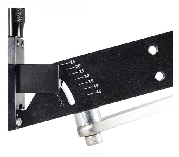
The sharpeners angle should be set to 300 for optimal cutting and due to the sharpeners design, the angle grinders cutting edge will now be perfectly aligned to allow the defined angle to be ground into the blade by simply moving the angle grinder up and down the blade which is the only movement the articulated arms allow.
Setup didn’t take long and after a few grinder passes, I had a nice sharp edges on the blade.
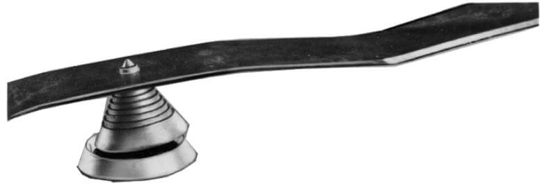
Once the blade was ground, I checked the blade for balance with a cheap and cheerful gadget, unfortunately the blade on my Titan Mower has an oval hole, this means getting the blade centered on the cone is difficult.
As the cone balancer was basically not really compatible with my blades oblong mounting hole, I bought from Amazon a Oregon blade balancer.
I have subsequently found out that it is not possible to get replacement blades for the Titan TTB833LWM 230v corded mower purchased from Screwfix, if I’d known this, I wouldn’t have bought the mower.
Conclusion
Obviously I would like to support the original developers of the blade sharpening product, but the UK price point makes this unaffordable to me, I therefore took a chance with the Chinese marketplace, Aliexpress.
It must be said that the quality of the sharpener is superb, all the attachments were included and I’m very impressed with the whole transaction, postage was more expensive than the tool itself, but nevertheless, I’m very happy with my purchase.
The Oregon blade balancer is a bit of self indulgence, the construction is solid and the rotation of the cone is very smooth, this will definitely last a lifetime
Now I have the time, I thought I would create what essentially is a home Operation and Maintenance, locally hosted webserved interactive manual.
The advantage of this is that all information relating to the house, individual rooms or equipment is held in one place, locally accessible on my home network either on my Desktop or mobile/ipad.
The starting block is my Synology Diskstation DS220+ Network Attached Storage (NAS) device;
The DS220+ has an inbuild webserver, so it was fairly easy to upload web pages created using the free version of Microsoft Expression Web 4, this is great software as it allows for the creation of image hotspot links to be embedded in pages.
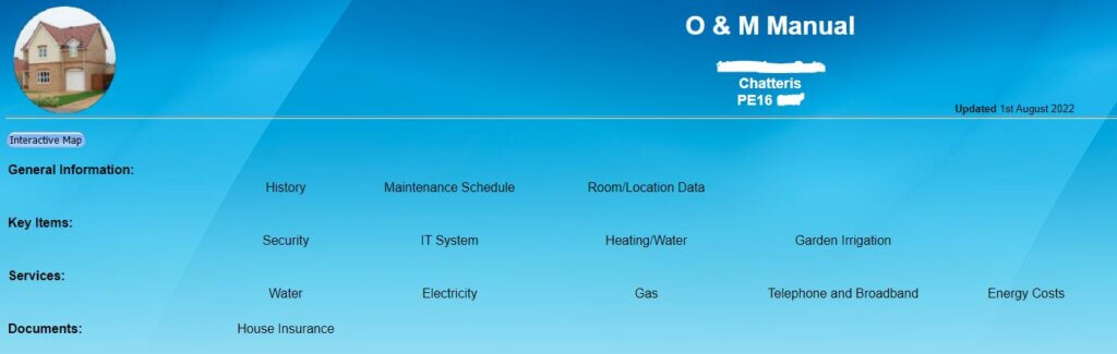
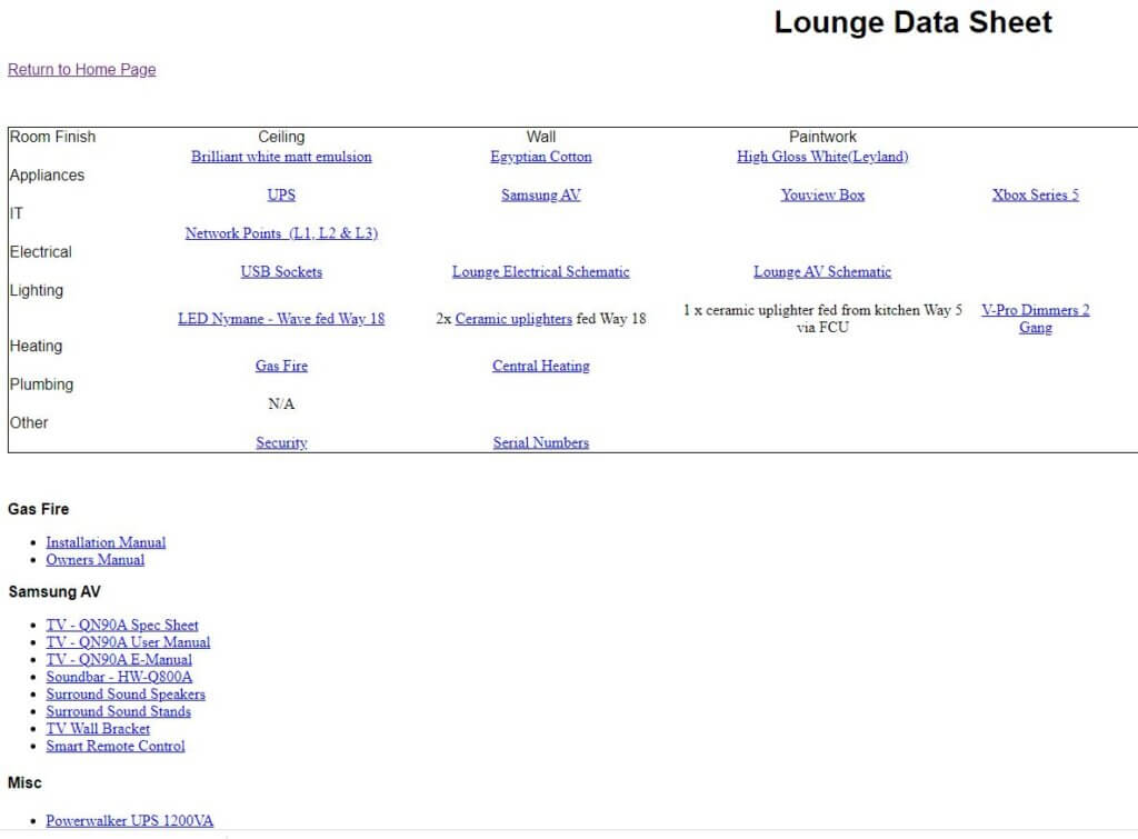
The main landing page is shown at the top of this blog, I can either click on the general description headings or click on the house image and an interactive view of the house will open:
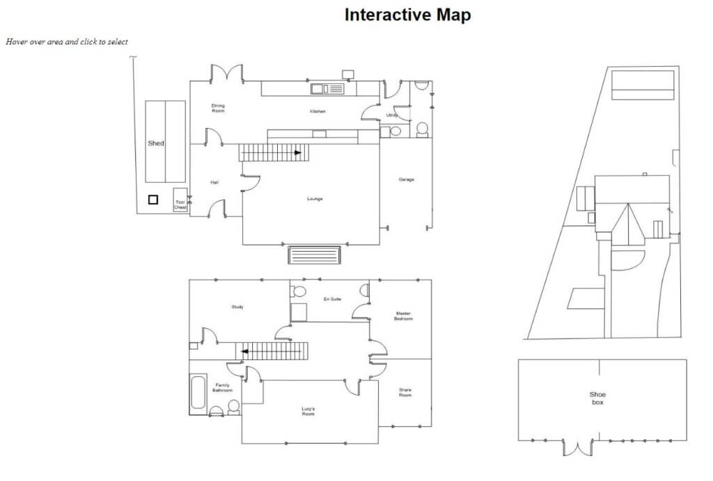
On the webserved image, as the mouse hovers over an area, this becomes ‘clickable’, on clicking, this takes you to the specific area of interest, as an example, hovering and clicking on the Lounge take me to:
This gives me access to room finishes, equipment manuals, serial number records and user guides, TV wiring, room electrical schematics and further links to specific, more detailed information of broader areas, such as the security system and central heating for example.
QR Code Labels
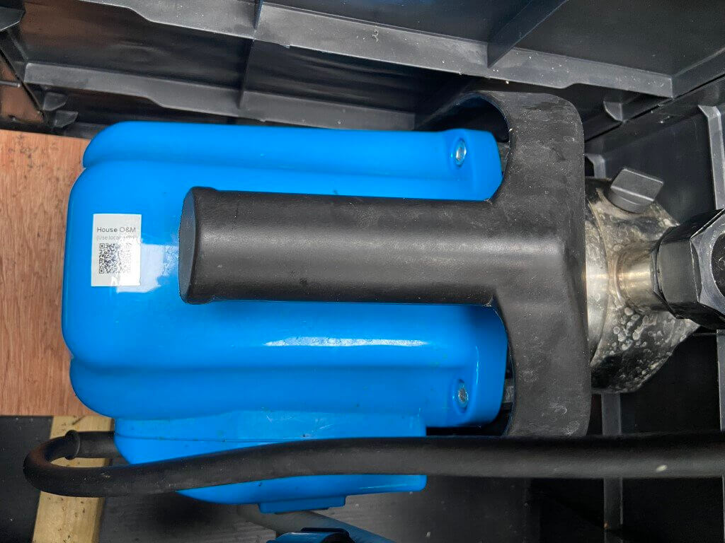
To enable quick access to information held on the webserver, I’ve used a number of QR code labels, to illustrate this, the pump for my irrigation system has a QR Code attached which will take you to the pumps manual:
Viewing the QR Code using a phone or ipad camera will automatically open the link to the webfile.
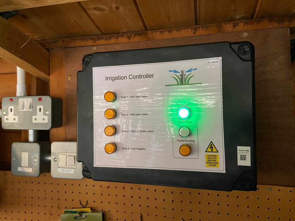
For more integrated projects, QR Codes are attached to the equipment linking to detailed, multi linked page/s:
Irrigation system is used in this example –
The controllers QR Code links directly to the Garden Irrigation page –
This linking to detailed information is incredibly useful to document on how things are configured, interconnected or interdependencies from a technical perspective, or more simply to store data sheets and supplier details.
Producing QR Code Labels
Small asset linking QR code labels are used:
The Brother P-Touch E550W printer has the ability to print a huge array of different labels, for asset labeling I use 18mm White Tape connecting the E550W printer to my PC using P-Touch free editing software.
The printer can connect via Wi-Fi or Direct USB cable to the software.
The above QR Code will take you to my other site, Chatteris Weather.
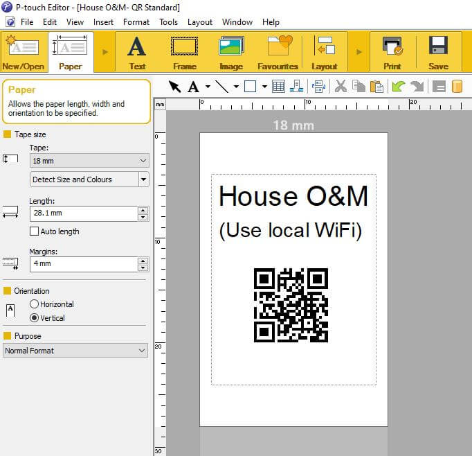
In P-Touch Editor software, select ‘Insert’ > ‘Bar Code’ with protocol ‘QR Code’ selected.
Within the QR Code software window, you simply paste the link in the ‘Input’ window and press save and print.
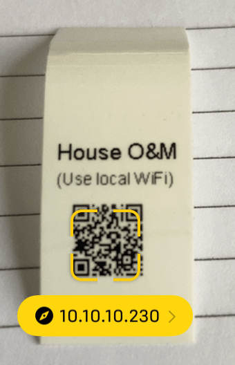
Viewing the QR code with a phone camera, a yellow box will appear with a partial link description, clicking in the yellow box will take you to the site originally entered in the ‘Input’ box.
Example display of correctly read QR Code
Conclusion – The use of a quick and easy way to access information makes life very easy, generating and maintaining the data does take time, but the information is available to anyone at anytime who needs it, (given they have the appropriate access rights to the Wi-Fi password).
A blog about stuff that interests me or I have done.
We use cookies on our website to give you the most relevant experience by remembering your preferences and repeat visits. By clicking “Accept All”, you consent to the use of ALL the cookies. However, you may visit "Cookie Settings" to provide a controlled consent.
This website uses cookies to improve your experience while you navigate through the website. Out of these, the cookies that are categorized as necessary are stored on your browser as they are essential for the working of basic functionalities of the website. We also use third-party cookies that help us analyze and understand how you use this website. These cookies will be stored in your browser only with your consent. You also have the option to opt-out of these cookies. But opting out of some of these cookies may affect your browsing experience.
Necessary cookies are absolutely essential for the website to function properly. These cookies ensure basic functionalities and security features of the website, anonymously.
Cookie
Duration
Description
_GRECAPTCHA
5 months 27 days
This cookie is set by the Google recaptcha service to identify bots to protect the website against malicious spam attacks.
cookielawinfo-checkbox-advertisement
1 year
Set by the GDPR Cookie Consent plugin, this cookie is used to record the user consent for the cookies in the "Advertisement" category .
cookielawinfo-checkbox-analytics
11 months
This cookie is set by GDPR Cookie Consent plugin. The cookie is used to store the user consent for the cookies in the category "Analytics".
cookielawinfo-checkbox-functional
11 months
The cookie is set by GDPR cookie consent to record the user consent for the cookies in the category "Functional".
cookielawinfo-checkbox-necessary
11 months
This cookie is set by GDPR Cookie Consent plugin. The cookies is used to store the user consent for the cookies in the category "Necessary".
cookielawinfo-checkbox-others
11 months
This cookie is set by GDPR Cookie Consent plugin. The cookie is used to store the user consent for the cookies in the category "Other.
cookielawinfo-checkbox-performance
11 months
This cookie is set by GDPR Cookie Consent plugin. The cookie is used to store the user consent for the cookies in the category "Performance".
CookieLawInfoConsent
1 year
Records the default button state of the corresponding category & the status of CCPA. It works only in coordination with the primary cookie.
PHPSESSID
session
This cookie is native to PHP applications. The cookie is used to store and identify a users' unique session ID for the purpose of managing user session on the website. The cookie is a session cookies and is deleted when all the browser windows are closed.
viewed_cookie_policy
11 months
The cookie is set by the GDPR Cookie Consent plugin and is used to store whether or not user has consented to the use of cookies. It does not store any personal data.
Functional cookies help to perform certain functionalities like sharing the content of the website on social media platforms, collect feedbacks, and other third-party features.
Performance cookies are used to understand and analyze the key performance indexes of the website which helps in delivering a better user experience for the visitors.
Analytical cookies are used to understand how visitors interact with the website. These cookies help provide information on metrics the number of visitors, bounce rate, traffic source, etc.
Cookie
Duration
Description
_ga
2 years
The _ga cookie, installed by Google Analytics, calculates visitor, session and campaign data and also keeps track of site usage for the site's analytics report. The cookie stores information anonymously and assigns a randomly generated number to recognize unique visitors.
_ga_92TJCVGJP2
2 years
This cookie is installed by Google Analytics.
_gat_gtag_UA_48800884_1
1 minute
Set by Google to distinguish users.
_gid
1 day
Installed by Google Analytics, _gid cookie stores information on how visitors use a website, while also creating an analytics report of the website's performance. Some of the data that are collected include the number of visitors, their source, and the pages they visit anonymously.
CONSENT
2 years
YouTube sets this cookie via embedded youtube-videos and registers anonymous statistical data.
is_unique
5 years
StatCounter sets this cookie to determine whether a user is a first-time or a returning visitor and to estimate the accumulated unique visits per site.
is_visitor_unique
2 years
StatCounter sets this cookie to determine whether a user is a first-time or a returning visitor.
sc_is_visitor_unique
2 years
StatCounter sets this cookie to determine whether a user is a first-time or a returning visitor.
Advertisement cookies are used to provide visitors with relevant ads and marketing campaigns. These cookies track visitors across websites and collect information to provide customized ads.
Cookie
Duration
Description
NID
6 months
NID cookie, set by Google, is used for advertising purposes; to limit the number of times the user sees an ad, to mute unwanted ads, and to measure the effectiveness of ads.
VISITOR_INFO1_LIVE
past
A cookie set by YouTube to measure bandwidth that determines whether the user gets the new or old player interface.
YSC
session
YSC cookie is set by Youtube and is used to track the views of embedded videos on Youtube pages.
yt-remote-connected-devices
never
YouTube sets this cookie to store the video preferences of the user using embedded YouTube video.
yt-remote-device-id
never
YouTube sets this cookie to store the video preferences of the user using embedded YouTube video.
yt.innertube::nextId
never
This cookie, set by YouTube, registers a unique ID to store data on what videos from YouTube the user has seen.
yt.innertube::requests
never
This cookie, set by YouTube, registers a unique ID to store data on what videos from YouTube the user has seen.


