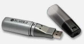
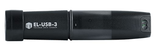
I’ve has a Lascar Electronics EL-USB-3 Voltage Data Logger for over 20 years and it works fine with no issues connecting to EasyLog software.
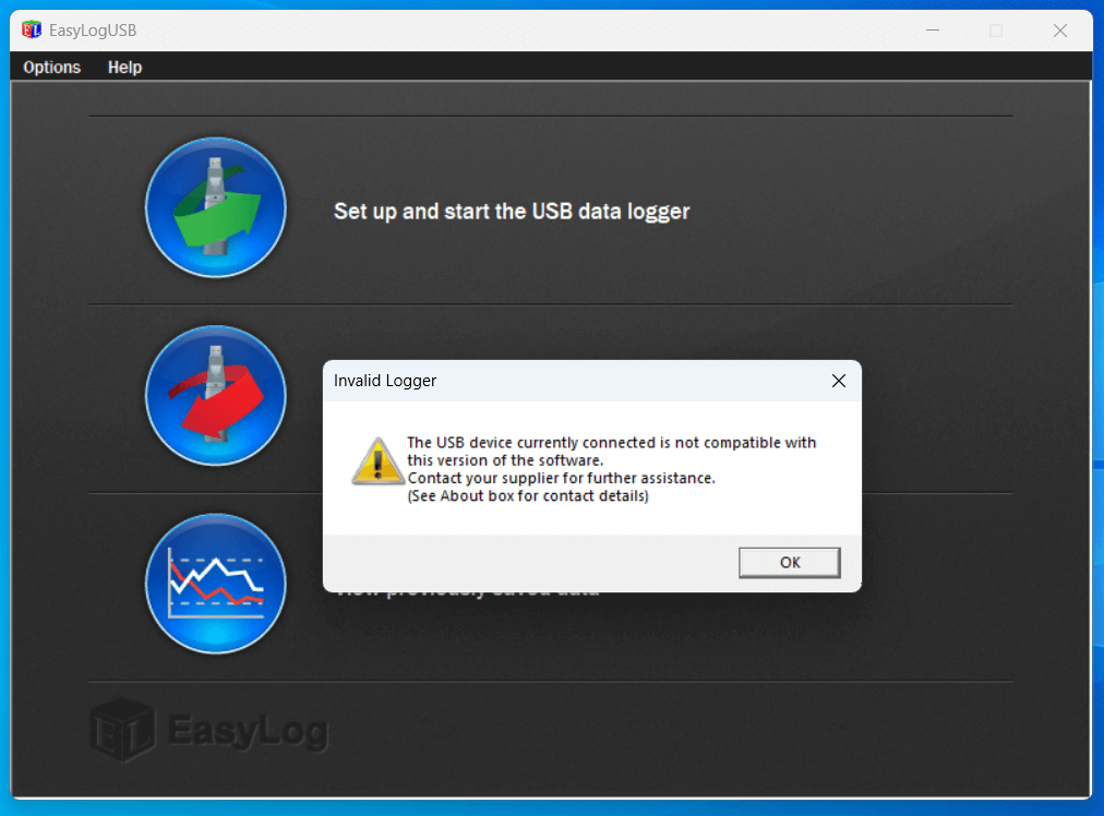
When I bought a replacement laptop, I downloaded from Lanscar Electronics the latest USB software, version 7.7.0.0, however, I ran into connectivity issues:
I went through the trouble shooting guide after changing the Tekcell SB-AA02 battery, but still no luck, even though the device was recognised in Device Manager.
I spoke to Lascar technical support who suggested the EL-USB-3 was faulty and needed replacement, this seemed odd as it was the software causing the issue, not the logger.
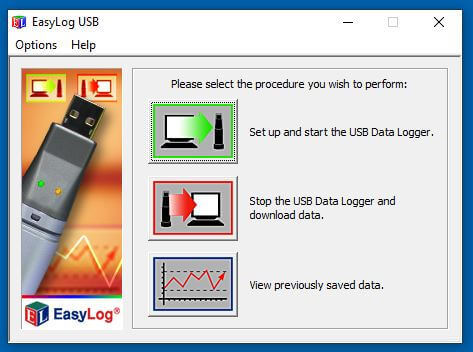
As luck would have it, I had a zip download from 2010 of version 5.53 and tried this on my Windows 11 laptop and it worked!
It seems as a rule of thumb that the latest all black loggers will work on the new software, whereas, the legacy silver loggers will need earlier software to work.
I’ve attached a link to EasyLog USB v5.53 software zip download – HERE
I have always loved the look of the Nixie tube and as an amazing Christmas gift from my better half, I got a Nixie clock kit to build.
The kit was from pvelectronics , also included in my gift was a GPS time receiver, Plexiglass case and PSU, assembly instructions for the main parts are below:
The packages came quickly and the contents were well packed as you would expect, assembly instructions and user guide are downloaded as no documentation comes with the kit.
Fig 1 – 5v regulator circuit
The assembly instructions are incredibly comprehensive, the build is designed in such a way that ‘stop and test’ points are used, enabling verification before moving on to the next build stage.
Fig 1 for example shows the components mounted to test the 5v regulation stage once 12v is applied.
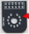
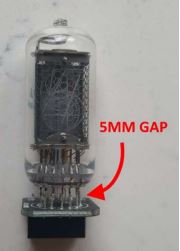
The only element of the build I struggled with was ensuring that the Nixie tube sits above the PCB by 5mm as per the instructions.
The problem is once all the Nixie tube wires are threaded through the PCB, I needed a way of not only getting the correct gap, but to ensure the tube is level in all planes, to solve this I used the 12 way SIL Socket Strips which come in the kit.
NOTE – This does mean going slightly ‘off-book’ to complete as otherwise you will have already soldered them to the main PCB.
I discovered is you slide SIL sockets from both sides through the Nixie tube wires between the PCB until the black plastic is touching the glass and PCB and then using light pressure on the PCB allows soldering knowing that the tube will be spot on.
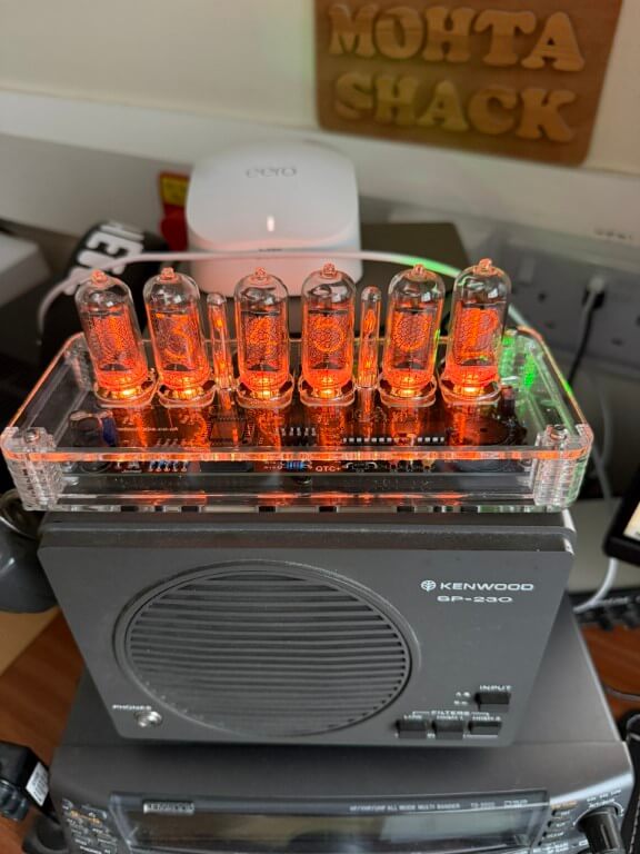
Completed clock looking brilliant and I’m very please with how it looks and all the features it has, for example the LEDs under the tubes can have there colour set to change every hour if you wanted too, as it is, I’ve set mine to orange (Red-3, Green -1 & Blue-0).
The only build variation from original, was to reduce the brilliance of the green power led, I replaced resistor R7 from 270Ω to 3.3kΩ.
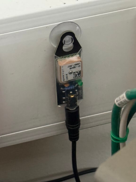
The additional GPS module only had 4 components to solder, the main GPS processor was already mounted on the PCB.
The GPS module connects to the Nixie clock and its a bit unnerving waiting for the green ‘sync’ led to come on 🙂
The Plexiglass case finishes the kit off in my option, giving that ‘class’ look as well as functionally keeping dust of the board.
I have no hesitation in recommending this kit and no, I’m not sponsored.
This blog covers the installation of a sub meter between the house and Anglian Waters boundary meter, the blog on locating this pipe can be found HERE.
The primary reason I want to monitor my water consumption in real time, is that Anglian Water supplied smart meter can’t do this as the App is typically 24 hours behind, a secondary reason is that I can take the opportunity to add an automatic shut-off valve linked to Home Assistant, so should a leak detector activate in the kitchen, the water supply to the house will close and also an alert will be sent to my mobile.
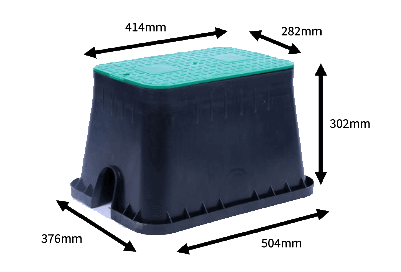
The equipment will be installed a standard size irrigation valve box.
The original idea was to install the valve box as near to the house as I could in order to reduce cabling and ensure a decent Wi-Fi signal gets to the control system, this idea failed when it was discovered that the water pipe near the house id over 1.5m deep.
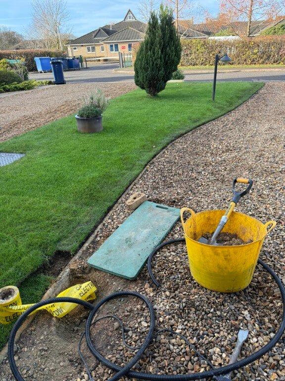
The next best option was to place the valve box in the hole I’ve already dug near the boundary meter which was used to trace the pipe.
This plan was to install the meter and valve inline with the pipe with the valve box sitting over the top of the kit, impinging slightly into the lawn.
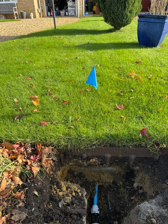
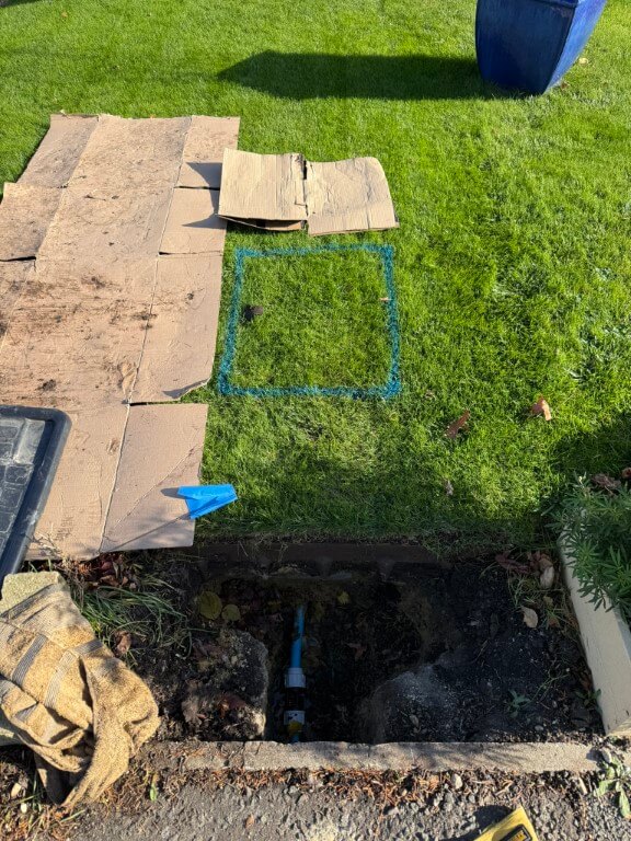
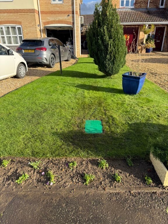
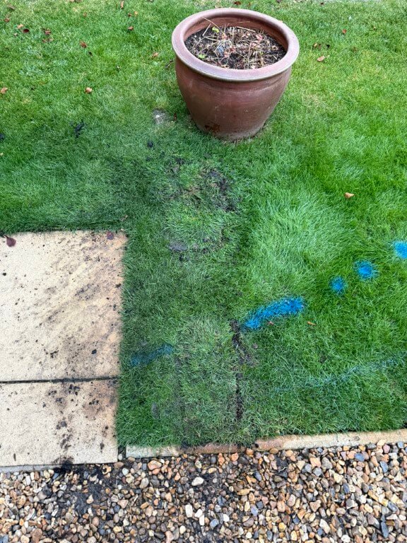
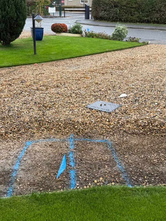
This came to a halt when I uncovered an Openreach duct under my lawn with the water pipe passing under it, so the only option left to me was to put the valve box just past the blue flag in the lawn marked in blue.
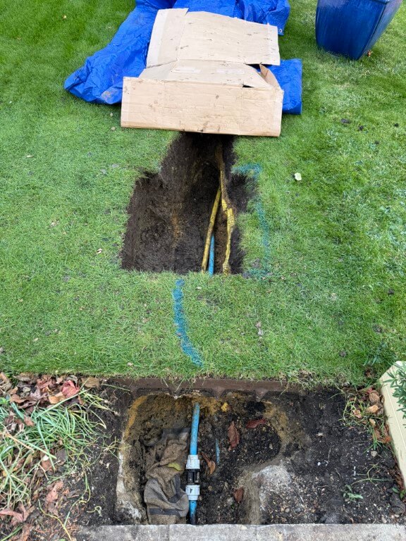
The dig went quite well, I was aware of the garden irrigation pipes which pass to the right side of the dig and also in front of the box.
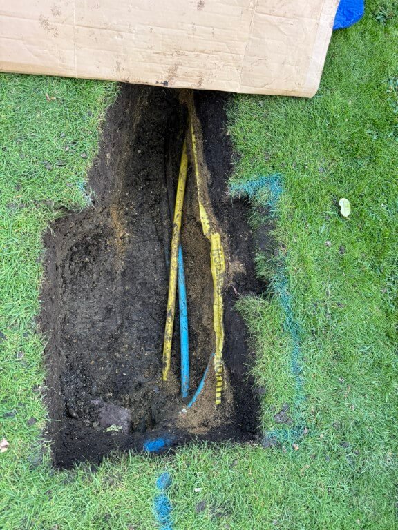
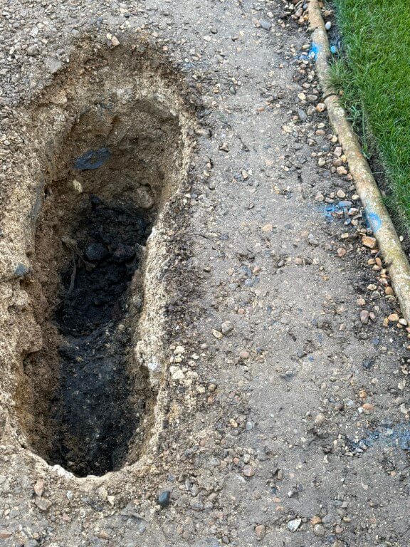
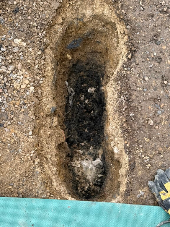
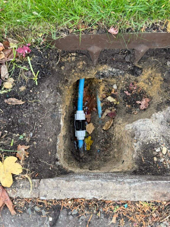
Typical with this project, I discovered the expected water pipe, but also the gas pipe and further down, the electrical duct to the house, all basically touching each other and off-center in relation to the valve box.
Due to the lay of the pipes I moved the valve box dig slightly to the left, this meant I needed to reposition the inlet and outlet water pipes.
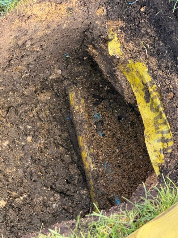
To compound the issue, the water pipe feeding my property is underneath the gas pipe, the close up on the above finished dig showing the irrigation pipe with marker tape, below this are the gas and water pipes.
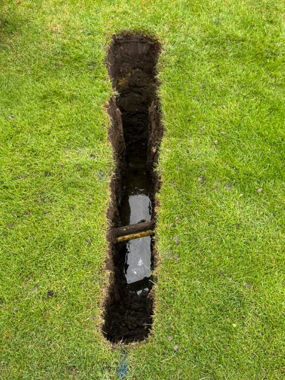
I dug further back to give me better access to the water pipe, also the length will give me additional flexibility, the plan is to cut the water pipe and get it from under the gas pipe so it will enter the valve box in the correct position, also the existing pipe to the boundary meter will be removed at the slip coupling and rerouted to the left of the existing position, again to get the pipe central in the valve box.
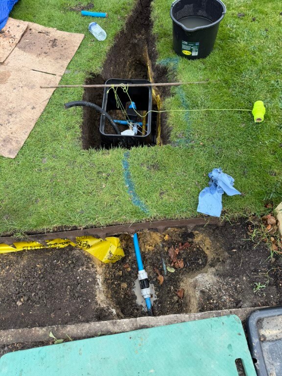
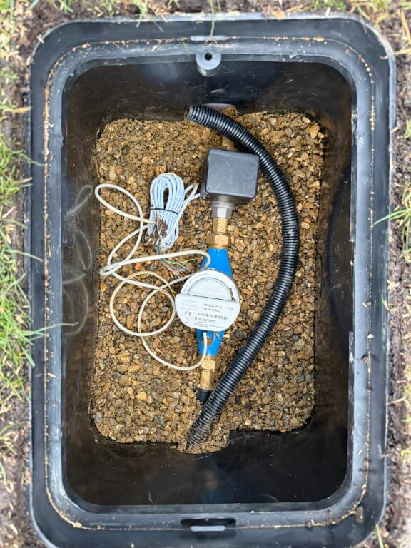
Valve box in temporary position after water connections made, the water connection turned into a problem for me as the pipe from the boundary meter under the grass to the new hole had been compressed and deformed to an oval shape by the Openreach Duct pressing down on it, with a stone beneath the pipe, a perfect storm.
The meant that I had to hammer the pipe through the soil from the slip coupling, only to find that I needed 1m of 25mm pipe to replace the damaged section, fortunately Taymor Plumbing Merchants at March were brilliant and cut me a piece for free, I did go back with chocolates and a Thank You card as they got me out of a right pickle.
The 25mm flexible conduit is to carry 12v power to the ESP32 which controls and reads the valve and meter respectively.
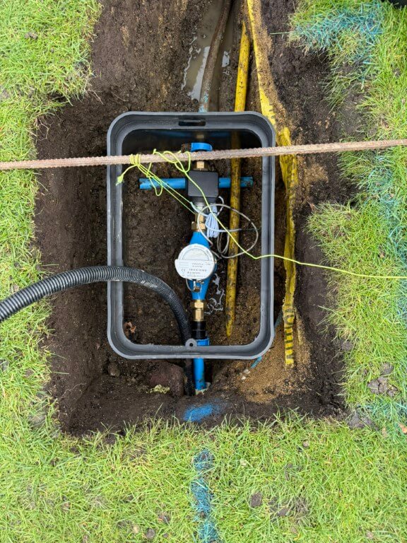
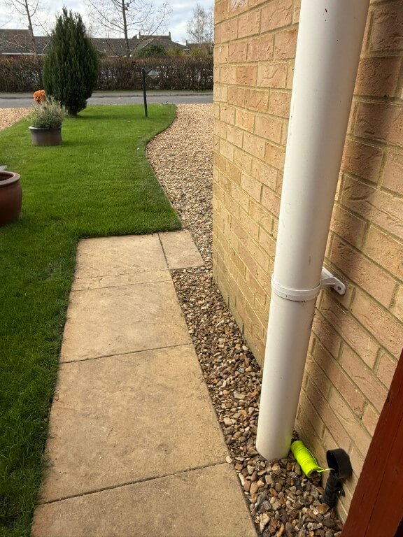
New pipe from slip coupling to sub meter via protective sleeve, exit pipe from the auto-valve to the house no longer under the gas pipe, making for a tidier install.
Valve box fixed in place with pea gravel and leveled to the grass, water pipes covered in builders and sharp sand to protect them and the longer section of exposed pipe to the house had pipe insulation fitted before being covered.
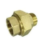
As I have pipe ‘fixed points’, the water meter is on flanged couplings allowing easy removal, I have also used a brass male to male cone seat union on the auto-valve, again to allow easy removal and replacement when required.
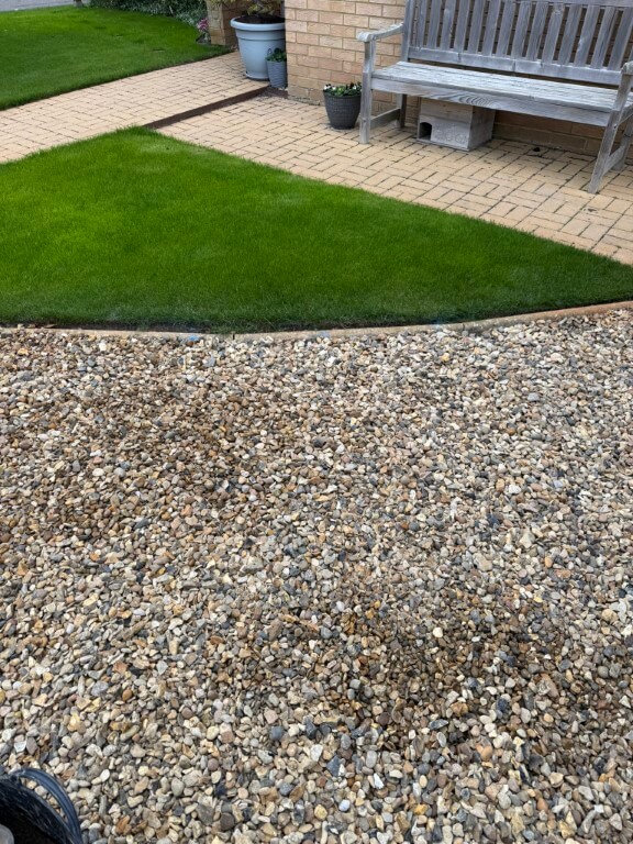
Grass and border restored to make the job look a lot neater, once everything starts to grow, the box lid will melt into the lawn.
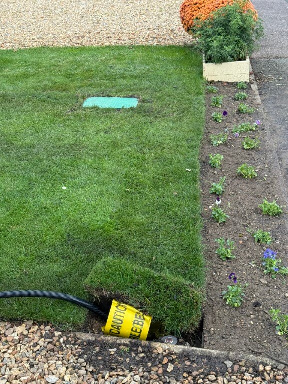
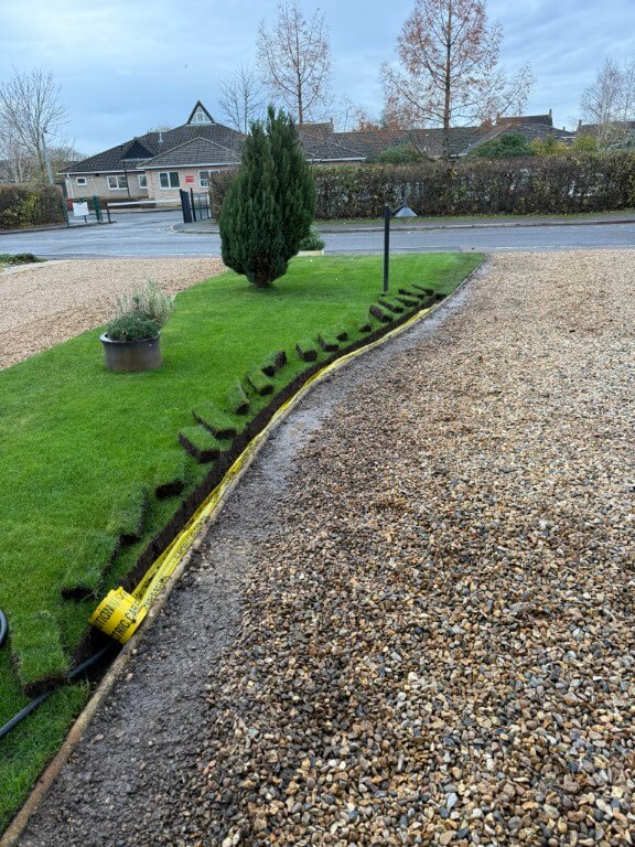
25mm Flexible conduit being installed back to the garage, the conduit has a marker tape over it and a shallow covering of sharp sand, due to concrete haunching supporting the round nose edging, the conduit is quite shallow, but I I wont be aerating the lawn this close to the edge, so it will be fine.
As it had been raining recently, the grass sods were easy to cut and lift out.
Conduit under the edging ready to drop in a trench in the drive which is yet to be dug, the last sod of lawn is next to go back and levelled down with the back of a spade, after that a mix of sieved soil mixed with lawn seed will be spread down the cuts and joints of the lawn where I have worked.
Flexible conduit all installed and draw cord in place ready to pull in 1.5mm2 two core cable for the 12v DC power to the ESP32.
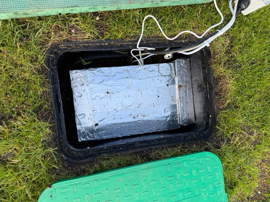
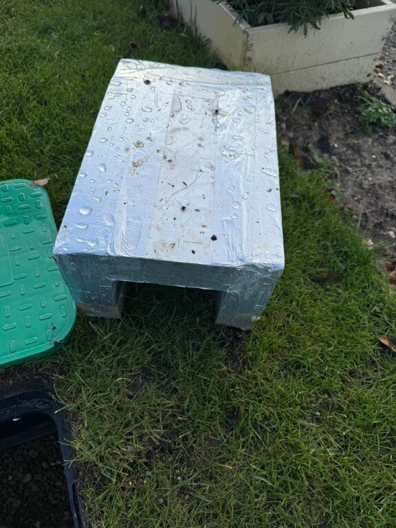
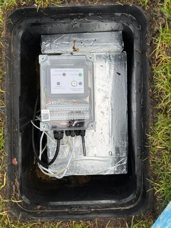
In the meter pit I have installed an cover for the equipment in the valve box using 50mm Kingspan insulation.
Home Assistant interface, equipment and wiring
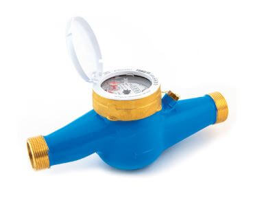
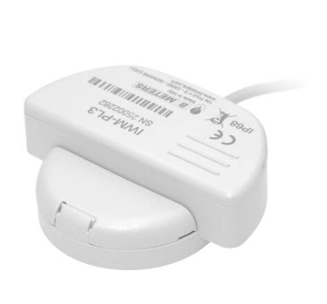
Working from the boundary water meter owned by Anglian Water, the connection was made in 25mm MDPE to my sub-meter which is a BM Meters model GMDM-I with a IWM-PL3 pulse emitter fixed to it and configured to register 1 pulse every 10 litres, both of these were bought from stockshed.
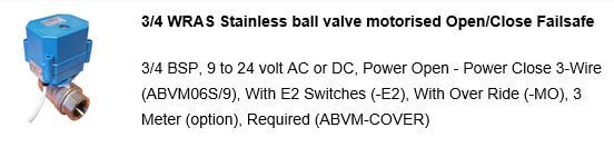
After the sub-meter is the automatic isolation valve, this is a ‘full bore’ valve so as not to reduce the water pressure to the house, (both the sub-meter and valve are 3/4″).
The automatic valve was bought from solenoid valve world, I opted for a version that monitored if the valve was open or closed and had the ability to be manually fixed open.
The valve operates on 9 to 24v, in my setup I’m using a 12v DC power source. My configuration is 12v permanently available to the valve and to close the valve, a switched12v hold open positive is removed, to open the valve, a 12v positive is reapplied to the control input.
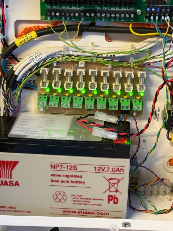
12v DC to the ESP32 and valve are via a separate fuse from my home alarm system power supply as this is battery backed up.
The valves position and operating commands are via an ESP32 connected to my Home Assistant dashboard by WiFi.
To enable future maintenance when dealing with two fixed pipe points, I used a 3/4″ male x female brass union end on the auto valve, this means I can easily remove/replace, either the meter or valve should the need arise.
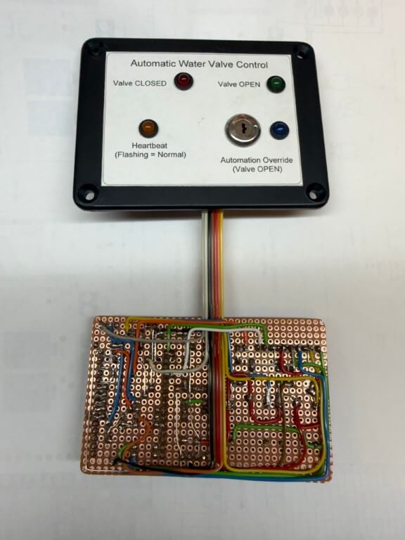
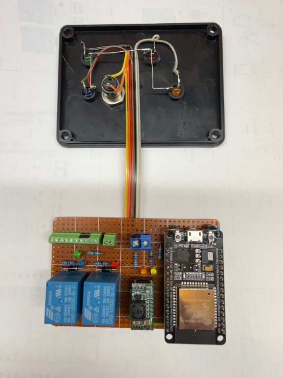
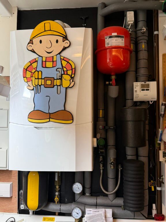
ESP32 Controller
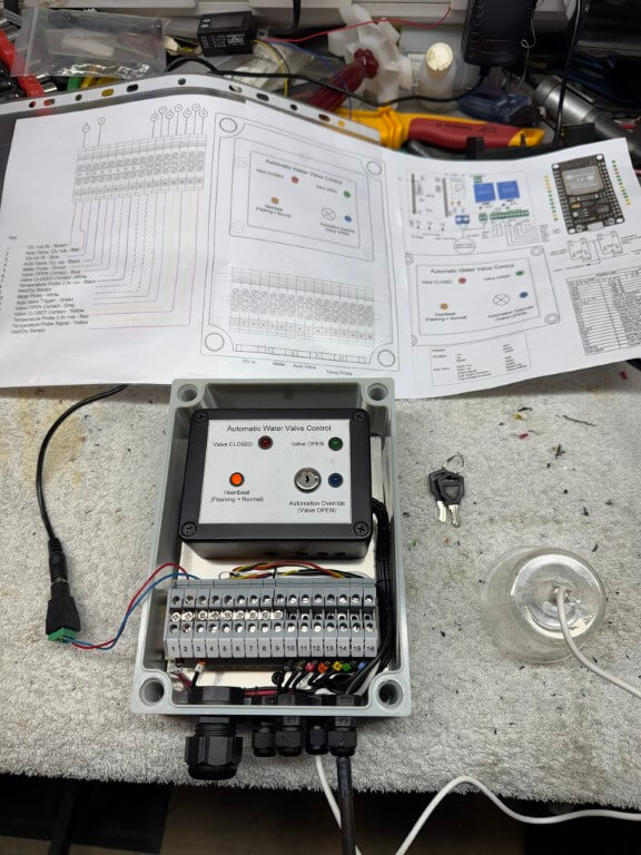
The above picture shows the completed controller boxed inside an IP68 rated enclosure, all cables pass through compression glands in a hope to reduce moisture ingress.
The QR code is linked to my ‘Home Manual’ on my local NAS, this enables rapid access to anything related to this project.
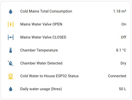
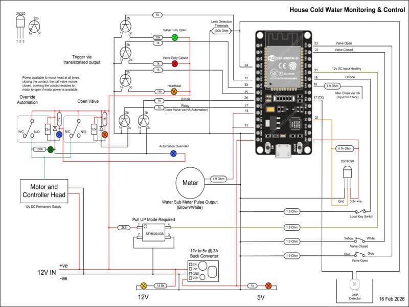
The ESP32 is the brains of the project, performing monitoring and control the following information to Home Assistant:
Auto-Valve position
External Temperature
Meter/Valve chamber – Dry or Wet
Remote override enable (to prevent any automations closing the valve)
‘Heartbeat’ (power and WiFi connection are ok)
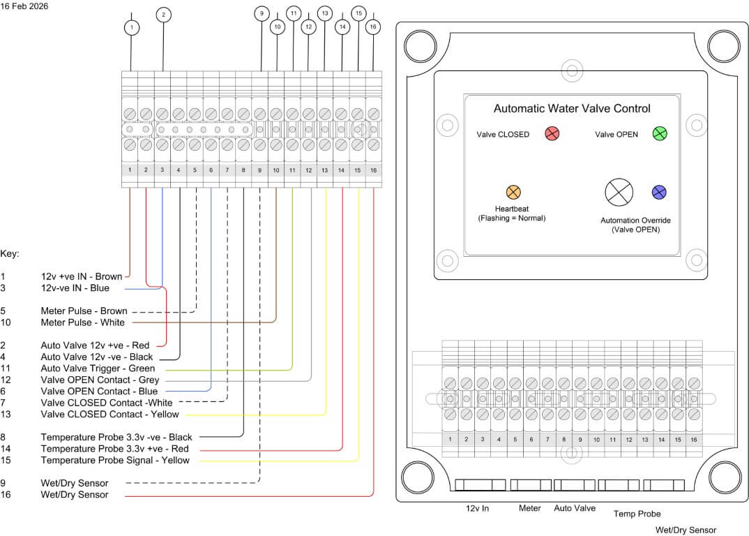
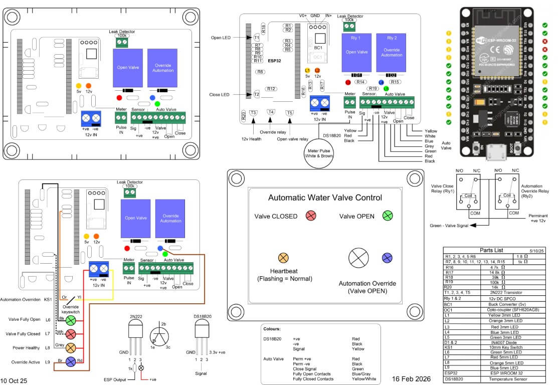
The first version of the controller was within a smaller IP rated enclosure, with field cable terminations made directly to the terminal blocks, however, the practicalities of doing this meant that it would be very difficult to easily remove the controller if maintenance was needed, therefore, version two used a larger IP enclosure and external terminals.
For ease, I simply soldered cables to the underside of the existing terminals and loomed the cables to DIN rail mounted terminals.
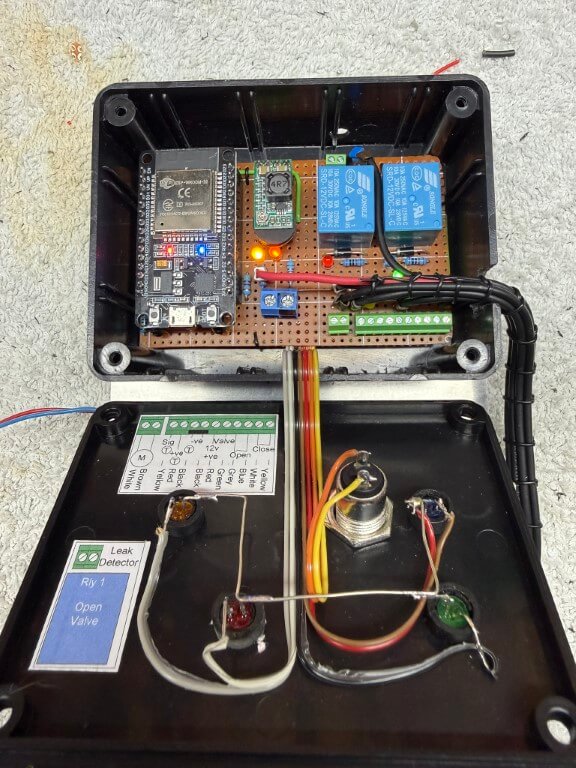
Completed controller within enclosure undergoing testing, the temperature probe for the chamber is fixed to the enclosure, to the right of this is the moisture detector secured inside a plastic cup.
The mouth of the cup will sit on the gravel base of the chamber with the height of the sensor set below the automatic valves motor and electronics, an alert is sent to my phone if moisture is detected.
The following files are of the wiring and code used:
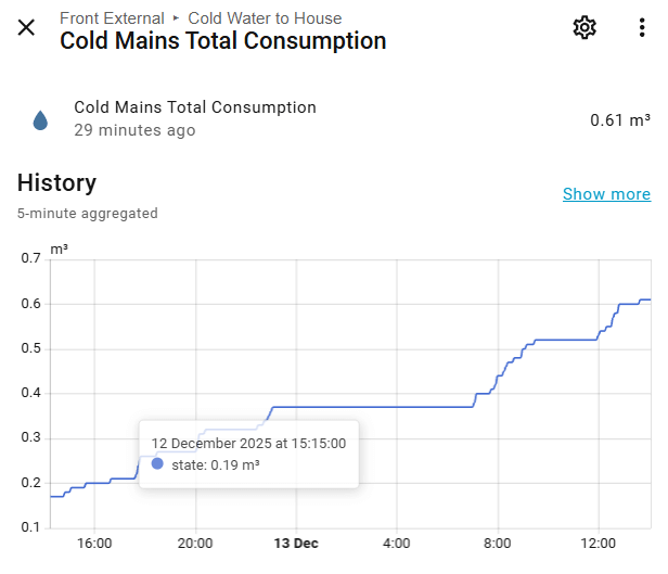
I’ve only got a small amount of tweaking left to do, but essentially the project is finally finished as information and control is flowing to Home Assistant.
One of things to resolve is getting the Total Consumption value to align with the boundary meters reading, although not absolutely necessary, it would be a nice to have.
After a few months in use, I noticed when the chamber started to fill with rain water and the water sensor operated, the indication to Home Assistant was rapidly turning on and off, to combat this, the YAML code was changed to make the water sensor turn on just before a reading was taken and then off, this also reduces probe corrosion, a futher modification was to add filtering and water detection sensitivity.
I hope you’ve enjoyed following this, a typical example of what seems a fairly easy job, turning into a bit of a pain with lots of ‘re thinks’ along the way 🙂
This is part one of a project to install a secondary water meter and automatic shutoff valve to my homes incoming water feed.
The first task was to locate the route my buried plastic (MDPE) water pipe takes to the boundary meter from the house, hopefully I can expose the pipe near to the garage.
The main reason for getting the meter near the garage was to enable easy connection to the Home Assistant interface and to ensure Wi-Fi connectivity to this.
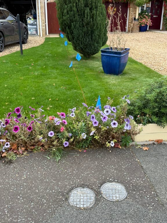
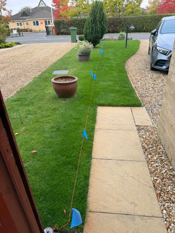
The images show from the boundary meter, (mine on the right!), looking towards the house, whilst the other picture is looking from the house with the assumption that the pipe is buried in a straight line.
The water pipe is 25mm and does not have any buried tracer wires or tracing features, therefore, I cannot use any radio detection avoidance/detection tools to impose a signal.
Excluding Ground Penetrating Radar, I could isolate the water and disconnect the pipe at the stopcock, and from there insert a metal ‘fish’ into the pipes length, giving me the ability to impose a radio signal on this and track it with a Cable Avoidance Tool (CAT), as this was ‘invasive’ and practically, very difficult I opted for the second method.
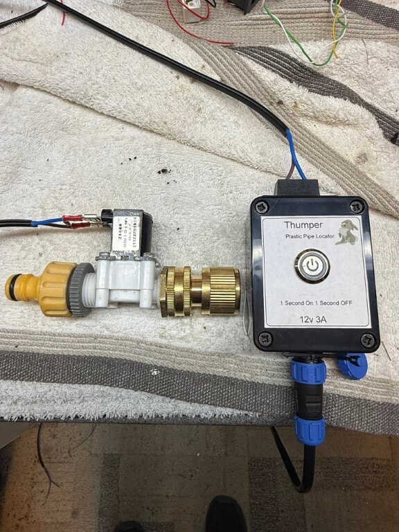
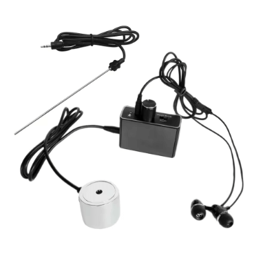
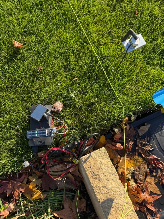
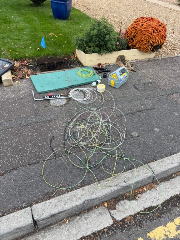
This method involves connecting a pulsing solenoid valve to an outside tap which causes an audible ‘water hammer’ which can be detected with a sensitive microphone, this is called the ‘Thumper’ method.
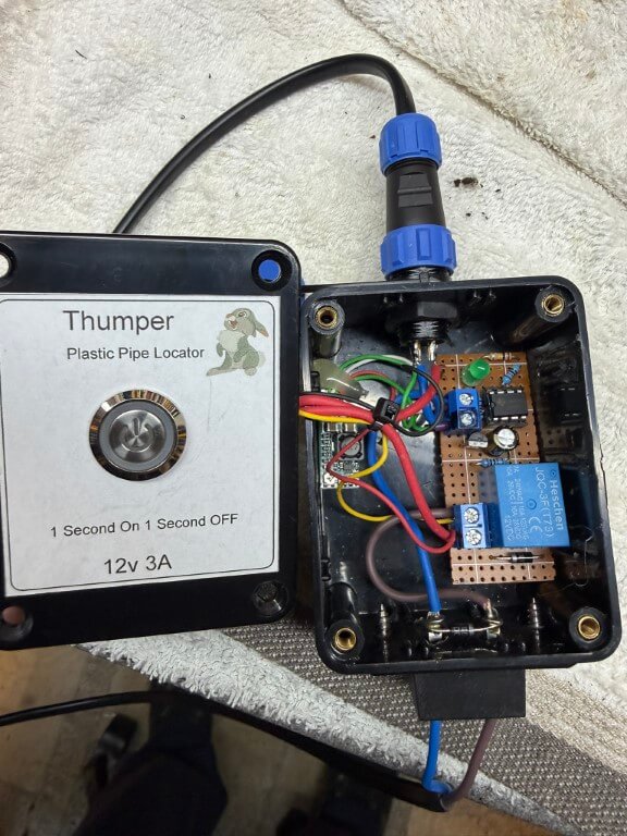
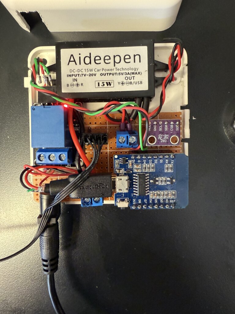
Complete ‘Thumper’ setup, the 12v solenoid valve is from Aliexpress and is pulsed by the circuit contained within the enclosure.
With the water being ‘pulsed’, the next part was to detect to sound and trace the pipes path based on how strong the pulse sounds, bearing in mind that the pipe is buried at least 500mm (should be 750mm, but 500mm was to the base of the existing boundary meter chamber).
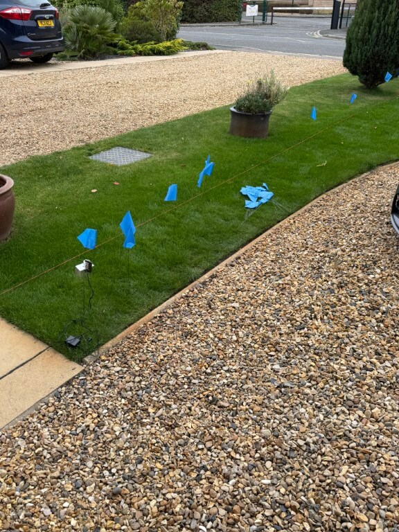
I bought a high sensitivity microphone and amplifier from Aliexpress for £23.99 which is incredibly good, I did clamp the circular microphone onto a piece of aluminum which had a length of stainless steel thin bar tapped into it, this allowed me to push deeper into the lawn in the hope of hearing the ‘Thumper’ noise.
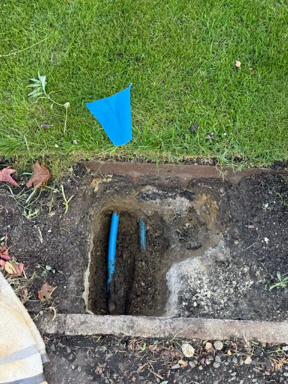
Each time I heard an audio signal, I moved the probe back and forth to find the strongest signal and marked this with a flag, as you can see, the pipe veered off the straight predicted line.
Day 1 – Dig (13 Oct 25)
As it was raining slightly and I don’t want my back to go, I decided to take it easy with the digging.
I started with a spades width rectangle hole and went carefully as I didn’t want to damage any services, I did know that the edging stones were cemented in, but was unsure how far this went under the lawn.
I didn’t have to dig too far down (300mm) to expose the incoming mains electricity and gas on top of the surface water drain pipework.
I checked the black duct using the ‘Thumper’, but its the electrical supply cable to the house, I did dig another hole to the side of this one, but it just confirmed that the surface water drain carried on to next doors property.
Filled everything back in ready for round two!
Day 2 – Dig (17-19 Oct 25)
I moved 700m nearer to the meter from the first dig and decided to basically trench across the lawn to give me a good chance of locating the pipe.
After digging 800mm deep and 1000m across, there was still no sign of the water pipe and using the ‘Thumper’, I could hear the rhythmic beat using the high gain microphone, but was unable to ‘hone’ in to a strong signal.
I could only conclude that the vibrations caused by the ‘Thumper’ was being transposed onto the neighbours water pipe and it was this I was detecting, rather than mine!
Day 3- Dig (20 Oct 25)
I wasn’t sure what to do at this point, I did ask for advice on my towns local Facebook page and had a really helpful reply, following this up, I was given a contact number of an ex-Anglian water guy, but the problem was unless the pipe was leaking detection was not possible with the tools and methods he had.
Prior to posting on Facebook a chap at ‘Man Shed’ suggested using water dowsing to find the pipe, when I got home, I was skeptical, but gave it a go with two bits of brazing rod, and blow me it gave an indication.
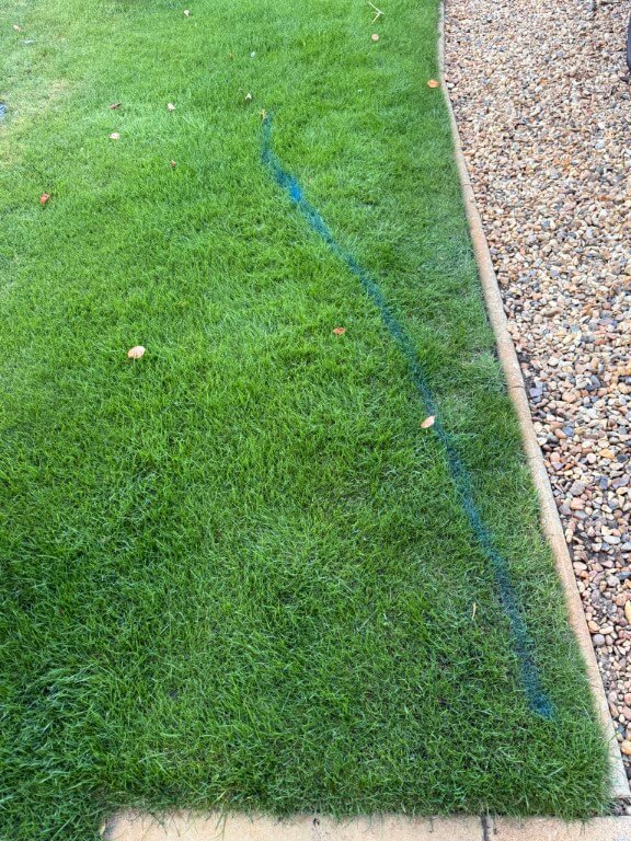
The far blue flag shows the location of the water meter, so I walked at 900 to this across the grass and drive and plotted when the rods crossed, repeating this I finally ended up with the second blue flag and a box location to dig in the hope I find the pipe.
I did also appear to pick up a sewage pipe which traverses across the front of my house.
Digging down through the drives hardcore I’ve come to a chunk of concrete which could be discarded builder waste or, more hopefully, a cap over the water pipe ducting.
Day 4 – Dig (21 Oct 25)
Oh well! My hopes were dashed when the concrete was broken away and I checked the area with the microphone for signs of an audible signal, but nothing.
No choice but to refill the hole and nip out and get some MOT type 1 to get the levels back, once compacted and covered over, nobody would know.
Plan ‘B’
Although the microphone pick up the ‘Thumper’ hydraulic pulses, I decided to build a ‘Pipe Knocker’ which simply hits the pipe using the same controller as the ‘Thumper’ to control a small solenoid, this will be attached directly onto the pipe from the meter.
My idea is that should allow me to hear a stronger pulse working from the meter to the house, rather than from the house to the meter.
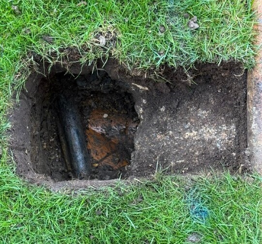
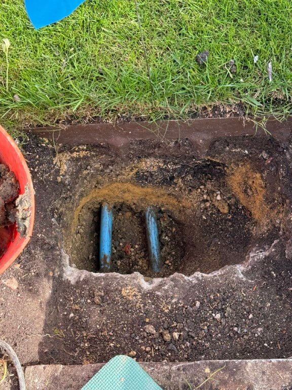
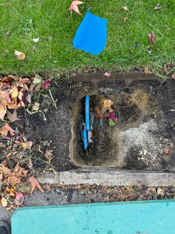
My 25mm feed is on the left and my neighbours is on the right, both directly buried at a depth of 400mm and protected with a layer of sand, I think that due to the close proximity to each other, its not going to be easy to be sure which pipe I’m tracing which ever method I use.
The nuclear and last option will be to expose more of the pipe and cut the pipe to insert a wire with an imposed signal on it that can be accurately tracked by radio detection, giving me a definitive location to dig.
Day 5 – Dig (22 Oct 25)
Bit more digging to break out the concrete giving greater access to the water pipe, this is in preparation to cut the pipe and use trace equipment to find the pipes route.
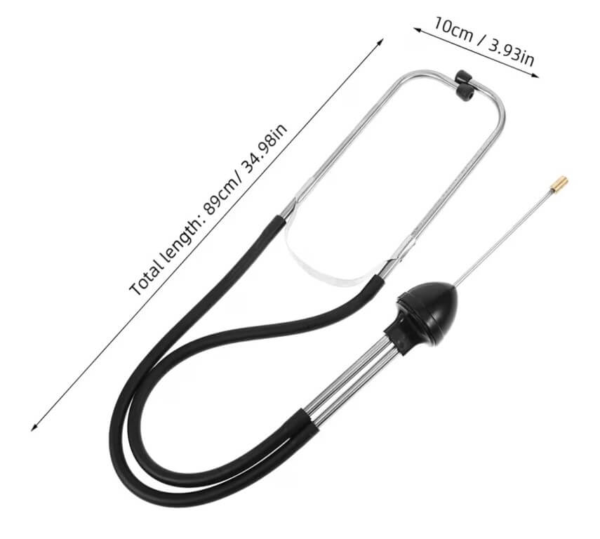
I tried the stethoscope from Amazon to listen for the ‘Thumper’ bit it didn’t work effectively for this application, there was a faint noise, but this soon disappeared as I moved further into the lawn from the meter and the main problem with the high sensitivity microphone was determining any form of direction as the sound generated from the ‘Thumper’ is omnidirectional, therefore, I abandoned the ‘Pipe Knocker’ idea.
Screenshot
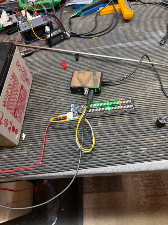
Last ditch attempt was to install an LED bar graph on the audio output of the microphones output.
The idea was to give me a visual indication of the strength of sound received by the microphone and enable me to ‘hone’ in the pipes route, alas this failed as the voltage changes to the bar graph were indicated fine for large vibrations but not with the low vibration signals.
Day 6 – (24 Oct 25)
Ok, I admit defeat, I’ve hired the following equipment from HSS:
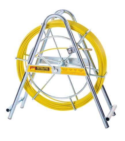
1 – Cobra with a single core wire tracer which I will attach the cobra, this will be inserted inside the open end of my 25mm water pipe and enable detection of pipe route and depth by the C.A.T.4+
70715 Duct Rod
2 – C.A.T 4+ radio detection device, tuned to the Genny frequency this device will determine the location and depth of the wire tracer within the plastic pipe.
49522 CAT4+
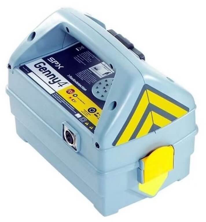
3 – Genny4 transmitter imposes a radio frequency on the tracer wire suitable for the C.A.T. 4+ to detect.
49523 Genny4
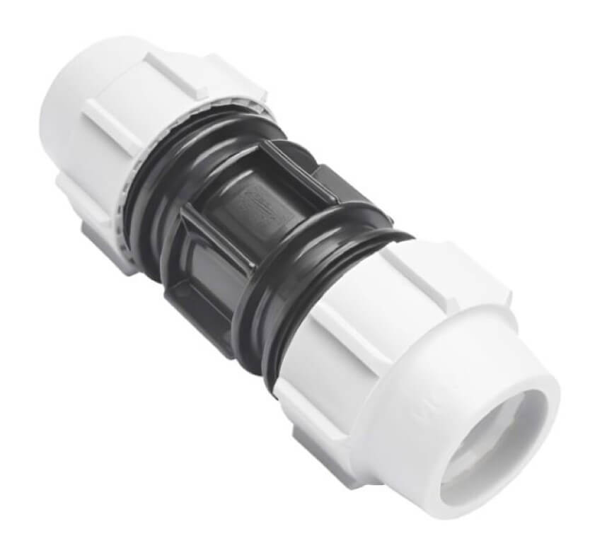
4 – I used Amazon to get a WRAS approved direct bury suitable Plasson 25mm Slip Coupling, this will be used to join the MDPE water pipe where it will be cut to allow the cobra and tracer wire to enter the pipe, a slip coupling will be used as pipe movement is restricted, being fixed points at each end. Another plus to a slip coupling is that pipe inserts are not required, so water flow will not be impacted by any restrictions caused by the coupling.
Day 7 – (27 Oct 25)
I don’t think HSS could have cocked this up any better, the whole experience was a pain in the arse, moving on…..
Cutting a long story short the depth of the water pipe at my preferred sub meter location was ~1.5m deep, so no wonder I could find it with my 800mm trench and water dowsing was a right bum steer!
Breaking this down:
The slip coupling length was marked on the pipe before cutting after I had double checked I was on the correct pipe, the house stop cock was off and that the streets isolation valve was holding.
I decided against using the hired duct rod (Cobra) until I had tried using a plastic conduit fish tape with a wire attached to push deep into the pipe, this worked effectively with little resistance.
Once sufficient wire was pushed into the pipe to where I would prefer the chamber for the sub meter to go, I attached the Genny4 and with the CAT4+, I traced the route and approximate depth of the detected wire inside the pipe.
Slip coupling installed and leak tested.
So that’s the end of this blog on finding a plastic water pipe, as you can see I tried a number of different non invasive techniques, but in the end a CAT and Genny was the only way.
The follow on from this blog is one about installing my sub meter and can be found HERE.
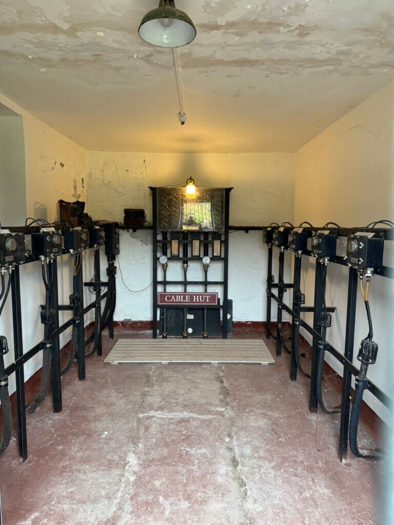
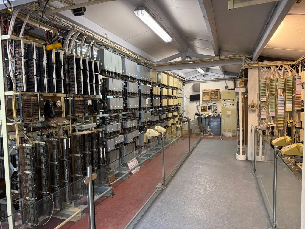
This museum includes a cliff hardened bunker and plots the fascinating history of subsea cable communications with interactive displays and an incredible amount of artifacts. The cable hut is where the cables land and is well worth a look.
This is an amazing place and I would highly recommend a visit as the website does not do it justice, especially if you like telephones as their working displays are fabulous.
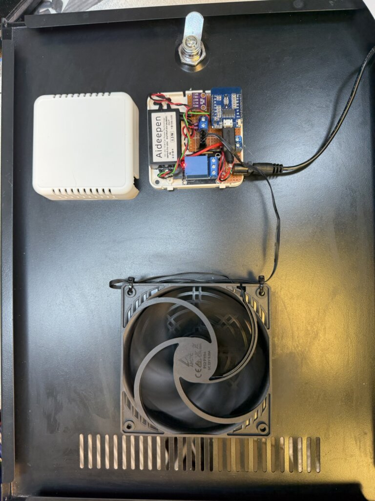
I follow ‘Speak to the Geek’ on YouTube and one of his projects was to control the speed of a fan based on temperature, this blog is how mine ended up.
Full credit goes to ‘Speak to the Geek’ and his homepage where a full description of parts and build are HERE.
The reason this tweaked my interest was to try and maintain a steady temperature in my home IT cabinet and it works with Home Assistant.
My current cooling arrangement has fans which simply trigger on high temperature, hopefully this will smooth out the ‘on – offs’.
I had a spare ‘Room Sensor Enclosure‘ which I bought from The Pi Hut which everything managed to fit inside.
The 120mm fan will turn on at 28oC at a preconfigured speed of 25%, as the temperature increases, so will the fan speed, reaching full speed at 31oC.
I have a automatic filling water bowl for the dog community in the area which is very popular, (Facebook Link), the water is fed by an 8mm pipe to the bowls float system and works really well, the problem I’m trying to stop is excessive water use, typically if the filling feed pipe becomes detached and goes unnoticed leading to wasting water.
My idea is to use a latching solenoid valve and flow meter linked to a Shelly Uni Plus with automation controlled by Home Assistant.
In normal operation the valve would be open and the flow to the bowl monitored, (the bowl takes 2.8 litres to fill from empty), should the flow exceed 5 litres, indicating excessive use, the solenoid valve will be pulsed by the Shelly Uni Plus and the flow turned off, if this occurs a message will be sent to my mobile.
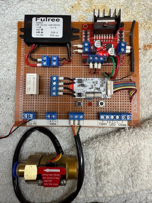
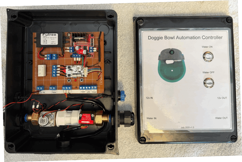
Water controller on bench testing.
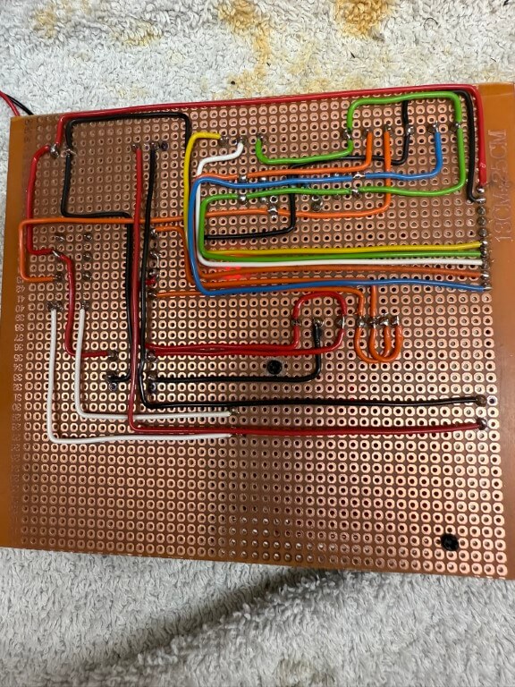
Underside of the controller board. 28 July 25, flow sensor 5v derived from the DC/DC converter directly.
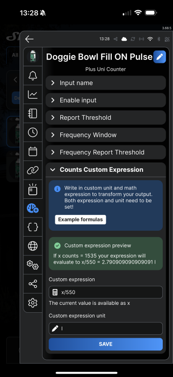
The flow sensor used is a YF-B1 bought from Aliexpress, the instructions said that 660 pulses = 1 litre, to calibrate this for the doggie bowl, I measured 2.8L into a bucket and the count was 1535, adjusting the expression value to x/550 until it read 2.79l, which is near enough!
The Shelly Uni Plus requires an ‘active low level’ pulse to trigger to register a count, the user guide quotes a trigger voltage of 1.5v, the flow sensor is powered from the 5v side of the DC/DC converter and works fine on the test rig.
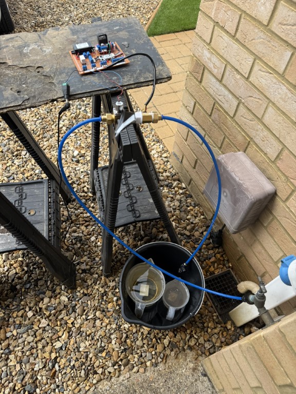
Test setup with mains pressure water feeding into the solenoid in the open state but with the valve at the end of the pipe closed, once all previous counts on the shelly were reset to zero, I opened the manual valve and filled the measuring jugs (2.8l), this gave me the counts recorded value.
Front cover laminated and stuck on with double-sided tape, all holes sealed with silicone sealant to try and keep the lamination in tact.
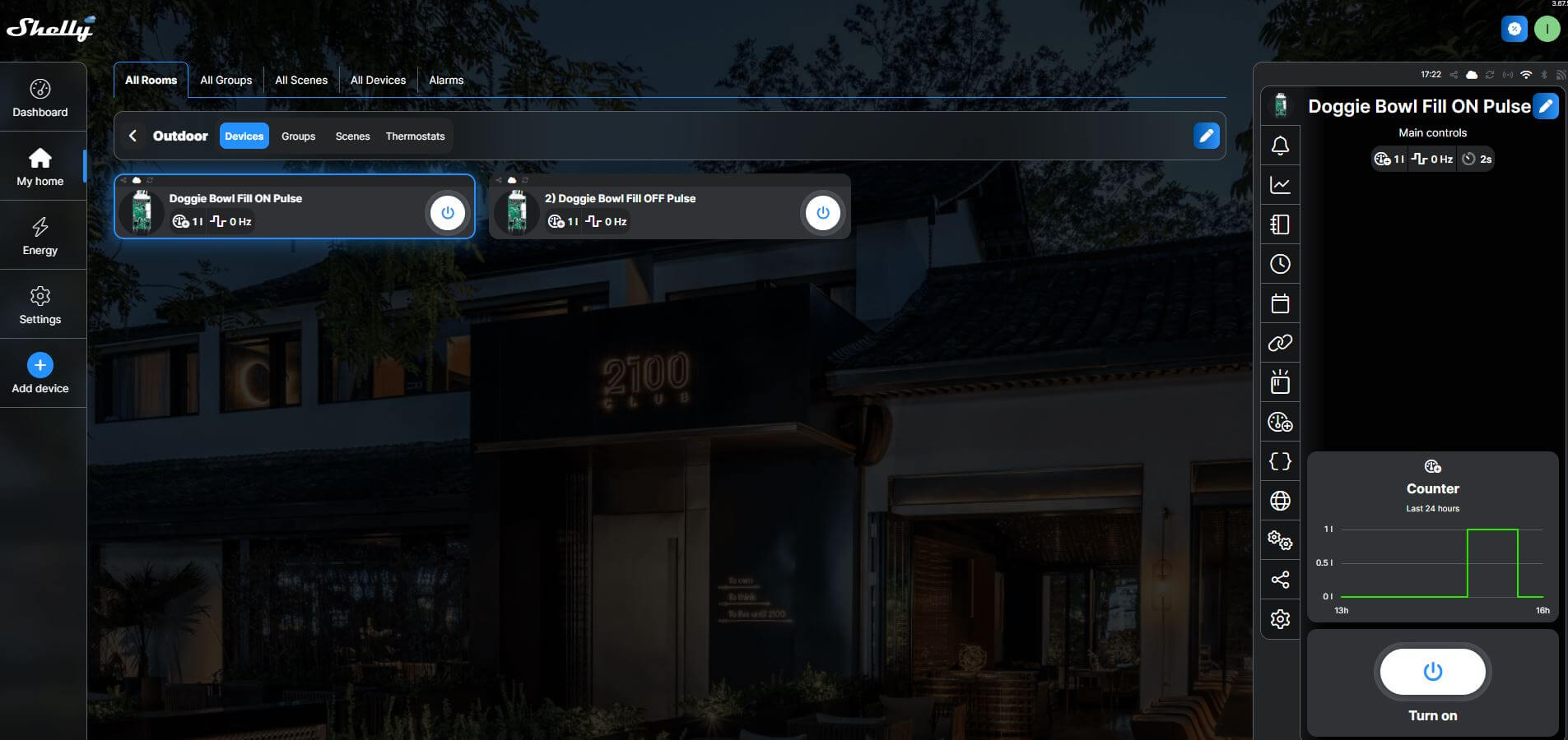
The above is a screenshot of the Shelly Cloud website displaying my Shelly Uni Plus, the ‘Count’ input was used for the flow meter and each of the two Shelly outputs were assigned as ‘ON’ Pulse and ‘OFF’ Pulse.
The latching solenoid valve requires a 30 millisecond pulse of 5v to latch open, reversing the polarity and applying another 30 millisecond pulse will close the valve, the Shelly has this feature built in.
The L298N was fed with 5v with the switching inputs going to pins IN1 & IN2, (IN1 & IN3 linked as were IN2 & IN4), this was done to get two mirrored outputs from the L298N.
One of the 5v pulsed outputs from the L298N goes to a latching relay, this enables a visual indication of the status of the solenoid valve via an LED, whilst the other 5v pulsed output goes directly to the solenoid valve.
Automation
Within the Shelly App is ‘Counts Custom Expression’ which for my flow meter is x/550 with the expression unit being l (litres) for a volume of 2.8L which is a complete refill of the doggie bowl.
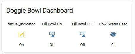
Home Assistant integrates with Shelly and shows the counter as either a counter value in Litres (set up above), and actual pulses recorded, both of these are cumulative values.
For my purposes I want the open solenoid fill valve to close once 5 litres have pasted through the flow meter in 24 hrs, indicating excessive use.
In order to get the counter value to reset at midnight, I used a Helper and defined the counter entity as a Utility-Meter with a daily reset time and renamed this as Bowl Water Used.
Within Automations, the rule is –
When Bowl Water Used is above 5 litres
Then Turn Off fill bowl & send mobile notification
Completed Project
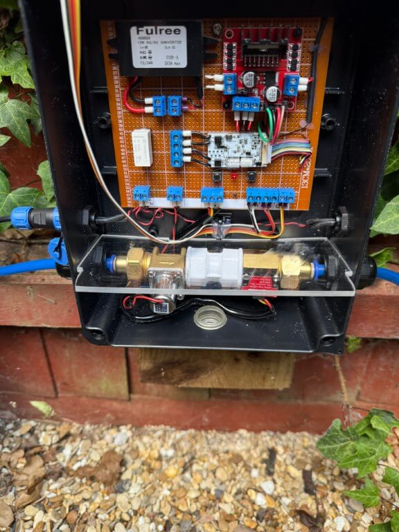
Unit plumbed in and 12v power getting connected, another 12v connection is opposite the inlet for future use.
I fitted a perspex divider between the water side and electronics to reduce any damage in the event of a leak, if any water does accumulate, the box has drain holes drilled in the rear of the box and a ‘tell tail’ clear grommet.
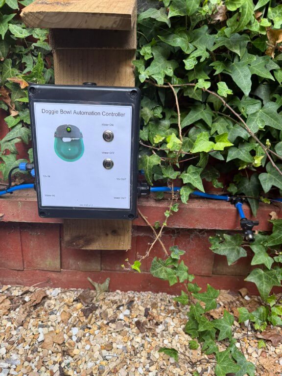
Green LED indicates if solenoid valve is latched open, local control of the valve is via the pushbuttons. On the feedpipe to the doggie bowl a drain down/test point is fitted.
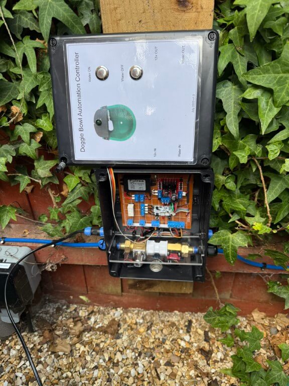
To limit rain getting on the control box, I’ve made a small wooden overhang, the enclosure is IP65 rated but I’m trying to keep water from getting into the laminated front panel details.
My Home Assistant display shows the valve position and water used, it is also possible to manually operate the solenoid valve from the dashboard.
Observation
When I emptied the bowl to clean it, the float valve operates to refill the bowl, however, water volume recording is ‘hit and miss’, I’m putting this down to the bowls float valve not being fully open, restricting the flow volume though the sensor leading to detection errors, however, opening the test point into a bucket at full bore, approximately 6 liters flows before the automation closes the solenoid valve to prevent water being wasted which is the main function of this project.
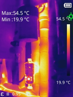
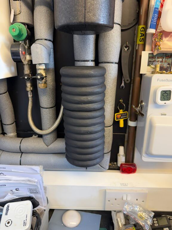
It has always bothered me that the magnetic filter which came with the boiler was uninsulated and no manufactures insulated jacket was available, so I decided to make one in order to reduce wasted heat as the filter is next to the boiler in the garage.
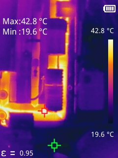
Thermal Image of filter when boiler heating water, the boiler setpoint temperature is 80C.
Image taken with Mileseey TR256B Thermal Imaging Camera, if you would like a copy of the PC software for this camera, use the contact form and I will send you a download link.
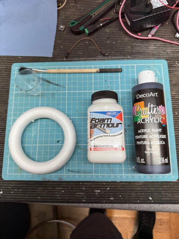
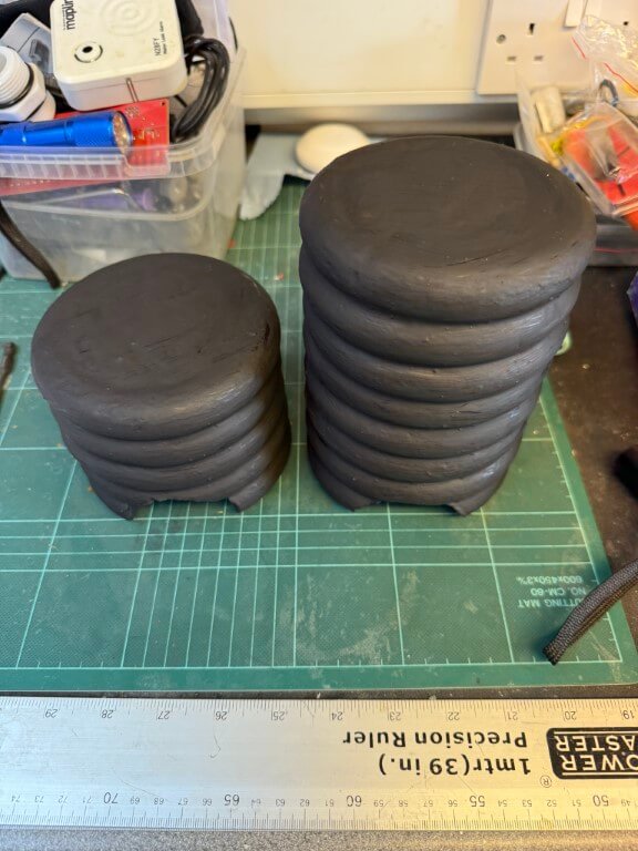
Construction was very simple, I bought 11.94cm foam ring circles for crafts from Temu (24 for £4.75), and glued them together with coving adhesive, making the top and bottom sections, (13 rings in total), the ends were filled in with an offcut of polystyrene found at the local tip.
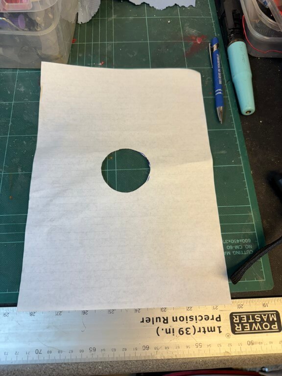
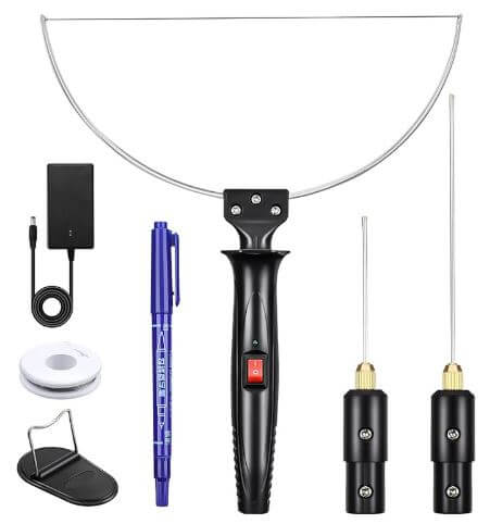
Each section then had half of the filter connection cut out using a ‘hot wire’ to match the pattern below.
Template of filter connectionHot Wire kit from Amazon
Once the two halves fit over the filter, the next part is to fasten them together, bearing in mind they will need separating for serving, for this I used 10mm x 2mm Neodymium disc magnets recessed into the foam, two on the lower half and two on the top, all covered in aluminum foil tape. The inside of the rings was also lined with this foil in an attempt to reduce heat loss further.
Once constructed I used ‘Foam Armour’ to strengthen the foam and painted the outside with Black Acrylic paint.
Finished insulated jacket in place.
Heat loss signature of design before lining and painting.
29 July 2025 – First two Chatteris Primary Nodes (PN515 & PN524) and downstream nodes online to FEx.
Note – I have no affiliation with Cityfibre and this blog is an historical record of new infrastructure coming to the town, also I’m not a network infrastructure engineer, so please let me know if I’ve made errors.
Benefits
Cityfibre do not sell broadband services directly, instead they have partnered with ~30 providers, including TalkTalk, Vodafone, Giganet, Sky and Zen to give you more choice, also as Cityfibre have installed there own fibre tubes throughout the town, other companies can rent these for their dedicated fibres.
Background
CityFibre is expanding its full fibre broadband network to Chatteris, Cambridgeshire. This initiative is part of a broader £122 million plan to upgrade hard-to-reach areas across the county, benefiting approximately 45,000 rural homes and businesses .(newswire.telecomramblings.com)
In Chatteris Netomnia primarily utilized existing Openreach physical infrastructure, CityFibre, however, has expanded on this by installing its own equipment, such as ‘Toby’ boxes, to extend connectivity to areas with direct-buried phone lines that Netomnia cannot serve .(chatteris.biz)
The first document relating to Cityfibre coming to Chatteris was in July 2023, (incidentally this was 7 months after Netomnia went live).
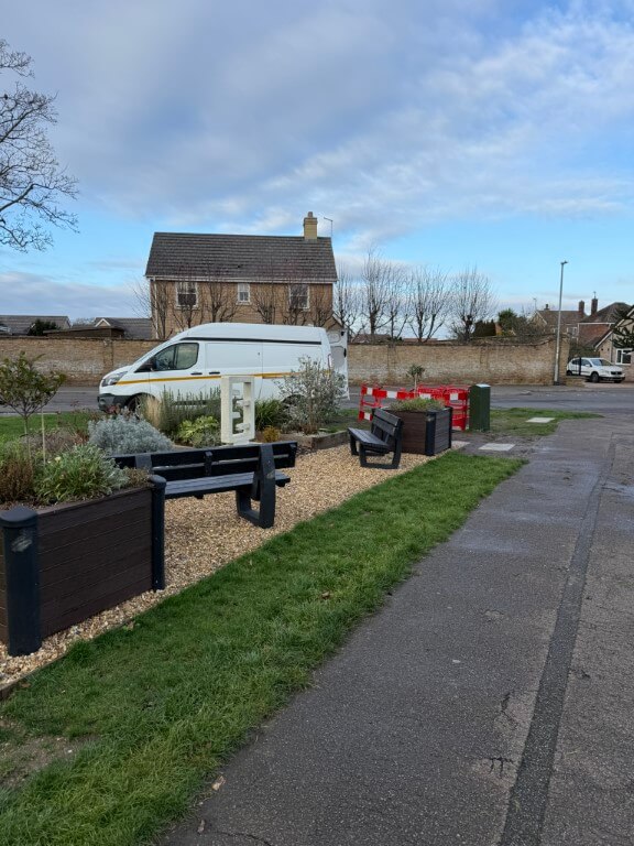
Infrastructure deployment is moving at pace since March 2025 with construction activities observed in various parts of Chatteris, the first cabinet was installed in Whitemill Road, January 2025.
For the most current information on availability in your specific area, it’s advisable to check the CityFibre postcode checker or contact local Internet Service Providers (ISPs) offering CityFibre services.
I must admit to being surprised that CityFibre are installing their own infrastructure in Chatteris as they will be competing with established overbuilt providers, such as:
BT Openreach
Virgin Media
Netomnia / Youfibre
The infrastructure installation method seems nearly identical to the Netomnia roll out, i.e. making extensive use of BT ducts, however, Netomnia did not install street cabinets or pavement ‘toby’ boxes in Chatteris, whereas, Cityfibre have.
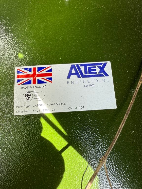
Street cabinets manufactured by:
It too early to see the exact scope of CityFibre’s installation works, civils are being undertaken by Granemore Group .
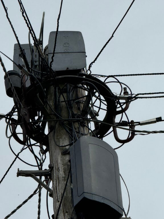
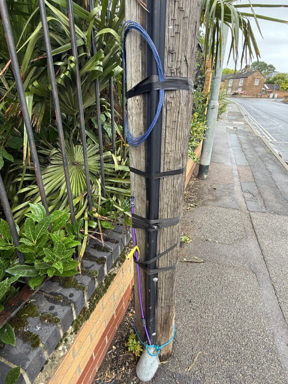
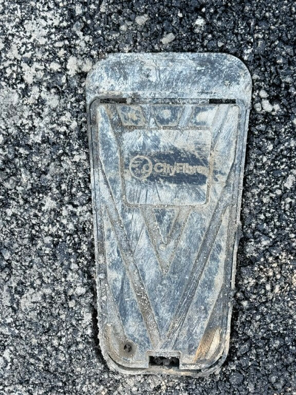
The above picture shows the evolution of communications from PO/GPO bare copper wire suspended between insulators then British Telecom multicore drop wires and now three fibre optic cable company connection points (BT, Netomnia & Cityfibre).
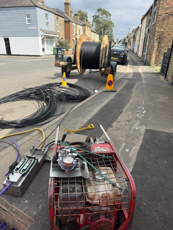
Spine fibre large single bore ducting being installed by sub contractors.
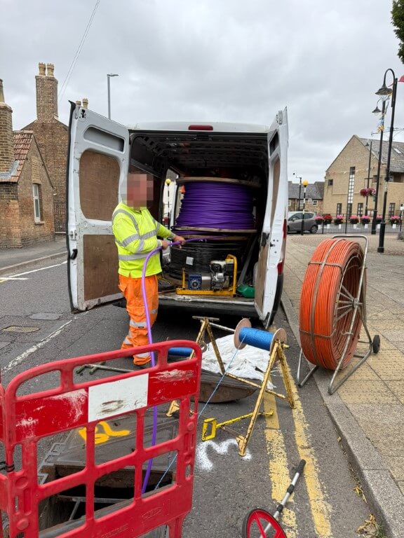
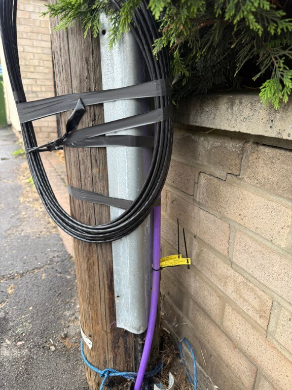
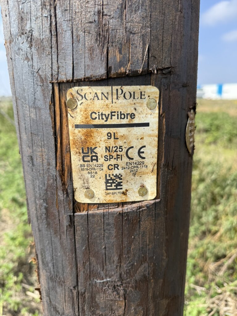
Quite a few poles around the town have the fibre duct in position ready to take the fibre optic cable to the top of the pole to enable Cityfibre customer connections.
4 core fibre blown in from the local Primary Node ready for the next team to splice this to an Aerial Secondary Node at the top of the pole.
48 core fibre blown in from the local Primary Node ready for the next team to splice this to Aerial Secondary Nodes at the top of this pole and also to aerial span over to adjacent poles for their pole top connection points.
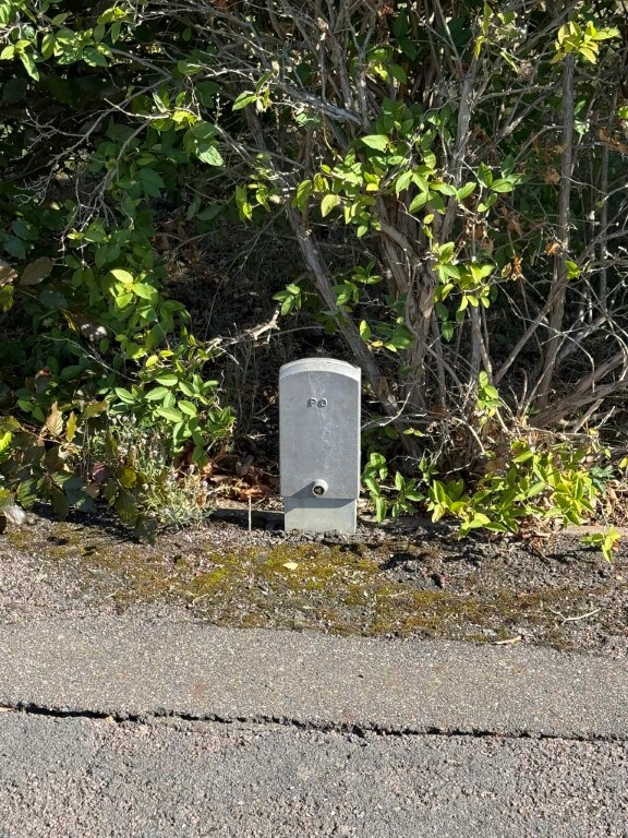
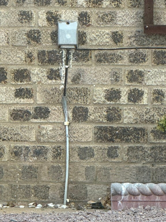
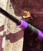
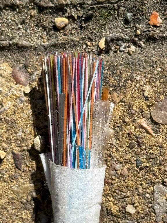
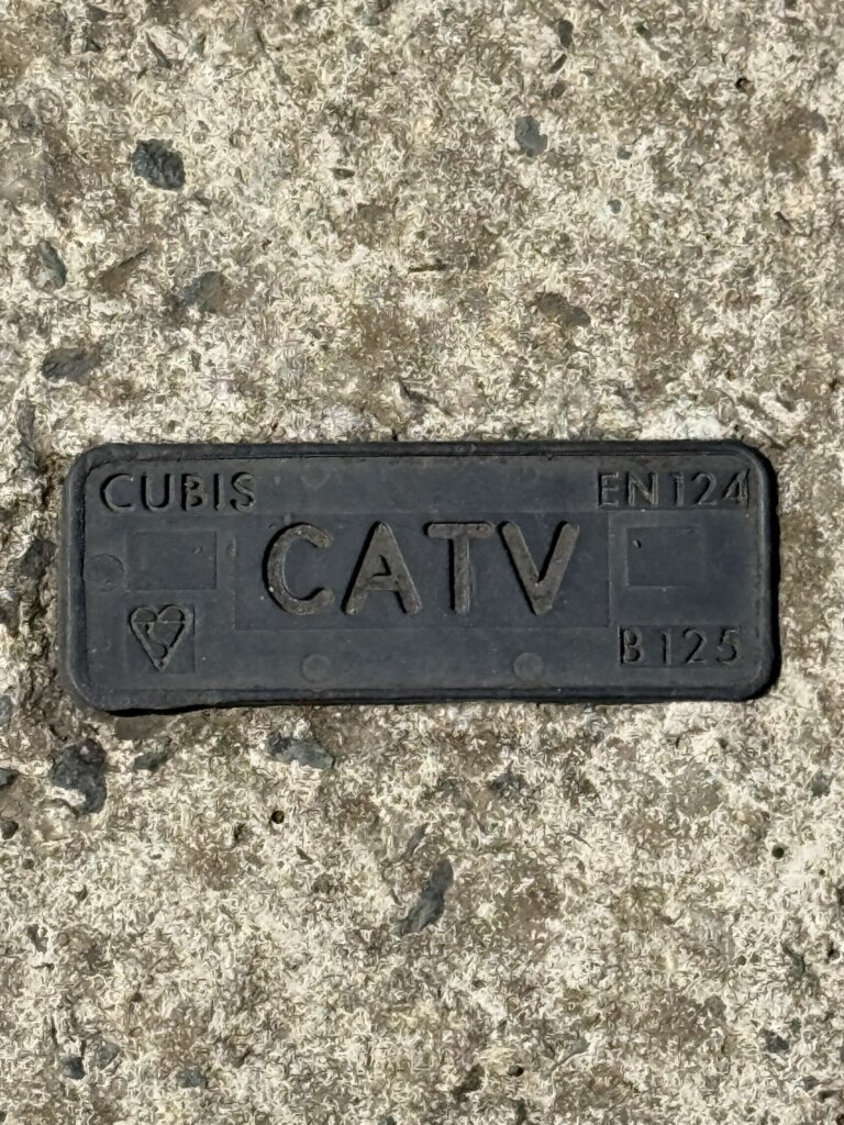
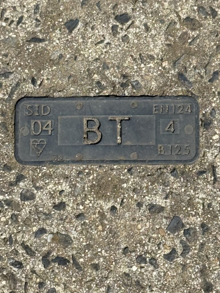
Areas in Chatteris, such as parts of the The Elms, Windsor Close and Green Park, BT use the ‘direct buried’ BT cable method cable, (this method can be identified by the images below), however, as CityFibre are installing ‘Toby’ boxes like Virgin Media did, this means that more choice will be available hopefully.
(14 August 2025 – Openreach planning application F/YE25/0602/PANR to install 2 x 10m fixed line broadband poles in The Elms, (Installed on the 30th August 2025))
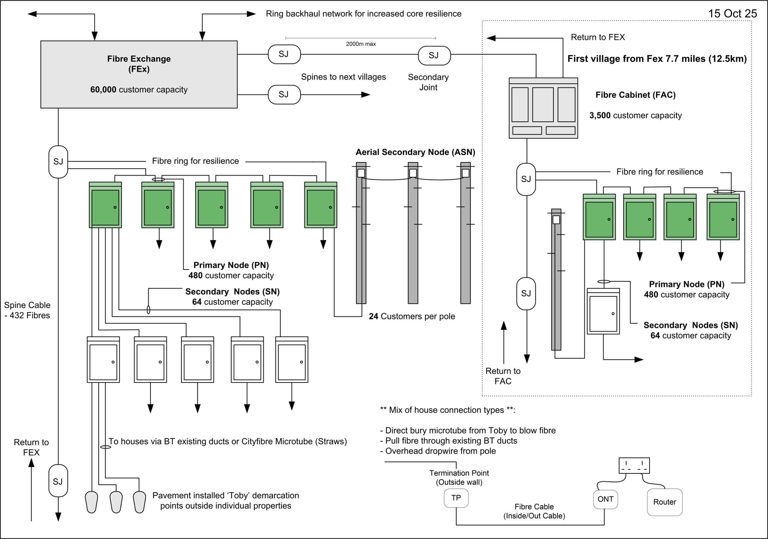
The Cityfibre Network- The journey from Exchange to your Premises
Information obtained fromCloudconnexand added expanded by myself
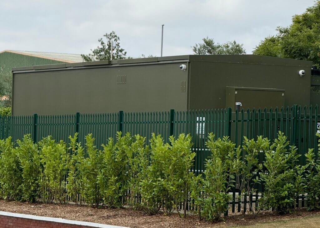
The CityFibre network is built upon a network of fibre exchanges, sometimes referred to as FEx’s. Each CityFibre Exchange is around the size of a shipping container and each facility powers around 60,000 connections with room for expansion. Each FEX is aligned to Data Centre Tier 2/3 specifications and houses 12 equipment racks doubling as a micro-edge data centre, each FEx not only powers broadband services, it provides a point of interconnect for Cityfibre partners and can help them realise their edge computing ambitions by storing and processing data closer to their customers .
Each FEx can support up to 7KW AC per rack, with DC rectification available for more traditional telecommunications carriers. In the event of a power outage, supply is automatically switched to A+B uninterruptible power supplies, with standby generators capable of running the entire site even at full load.
Resilience is at the heart of the CityFibre network and as a result each exchange is served by 2 physically diverse fibres, complementing the ring-based topology used for the core infrastructure build.
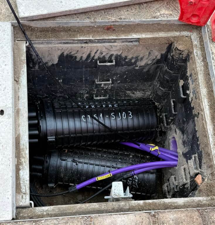
Fibres are ‘blown’ through tubes originating at the FEx, in Chatteris 6 x 432 core fibres form the main spines to areas of this and other local towns.
Each spine cable passes through Secondary Joints as pictures above, these are the breakout points to Primary Nodes or Aerial Secondary Nodes if remote from Primary Nodes.
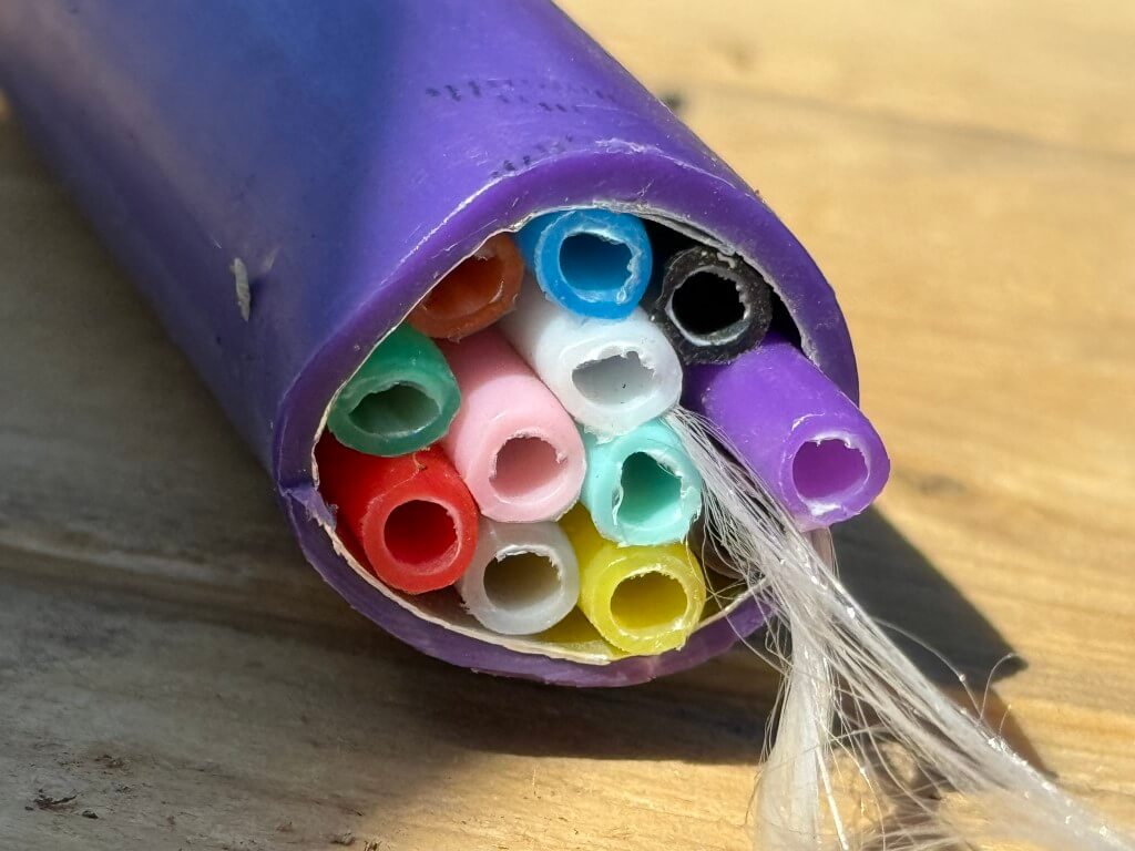
12 microtubes within cable sheath used for node interconnects.
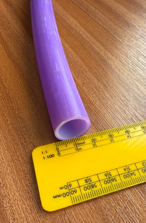
Spine Ducting
The 432 fibre Spine cable is blown through a larger bore duct.
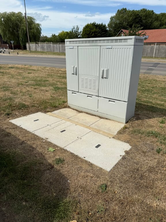
Fibre Cabinet (FAC) fed from the FEx and supplies a further 3500 properties. (Image is an example and not in Chatteris)
Primary Nodes
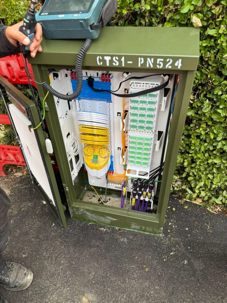
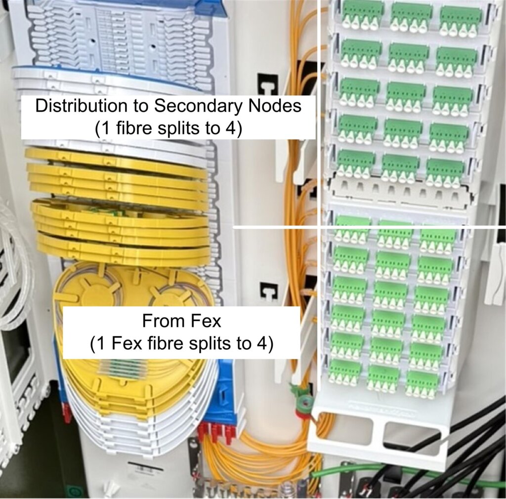
The FEx connects Full Fibre optical cables to the Primary Nodes via Secondary Joints. These are arranged in groups of 480 properties and are either hidden away underground or above ground in street cabinets.
The Primary Nodes are connected in a ring configuration to improve system resilience.
Fibres to Secondary Nodes and Aerial Secondary Nodes ready to be spliced and connected to the distribution side..
1 fibre from the FEx splits 4 ways, 1 of these ports is patched to the Secondary Distribution side outlet, enabling a further split to supply 4 Secondary Nodes each of which can connect up to 32 customers.
29 July 25 – Completed Primary Node.
Fibre side contractor is:
Screenshot
Secondary Nodes
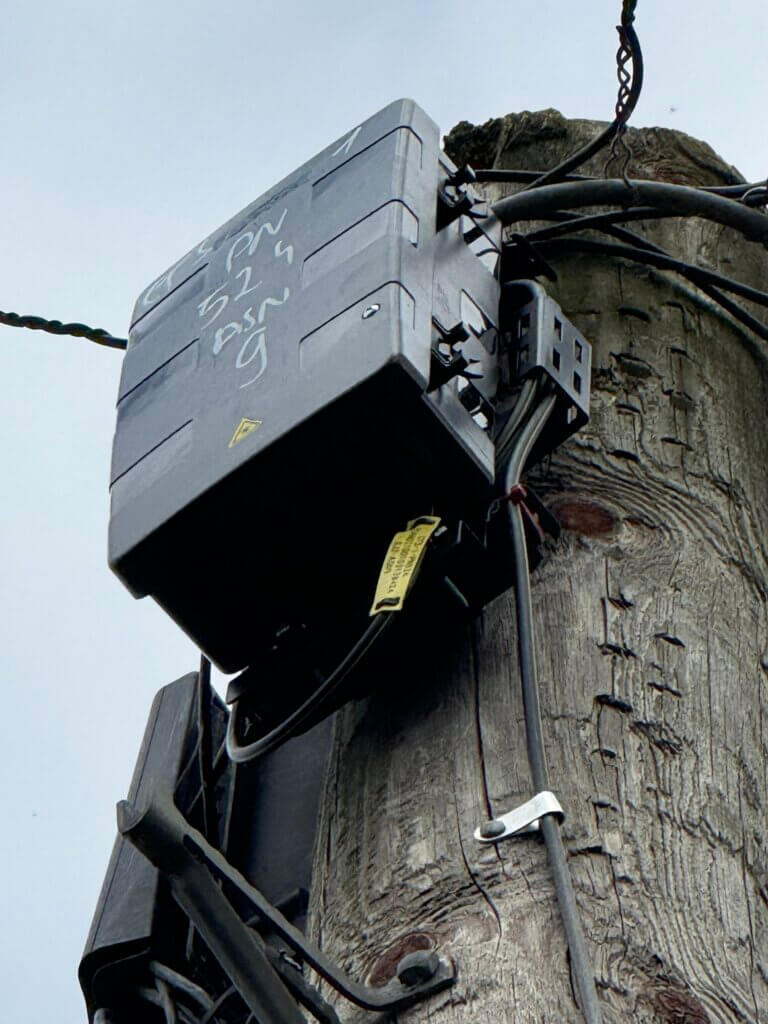
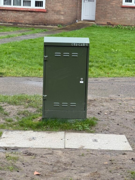
Secondary nodes are found in the form of street cabinets with 64 connection capacity, or equipment mounted on the top of an existing aerial pole, (Aerial Secondary Node – (ASN)). Secondary nodes bring the connection from the Primary Node to the street on which your premises is located.
Aerial Secondary Node, 24 customer capacity.
Within the ASN a single fibre is spliced to an internal optical splitter giving 8 outputs, therefore, three fibres have been spliced in the above ASN to give 24 customer connections.
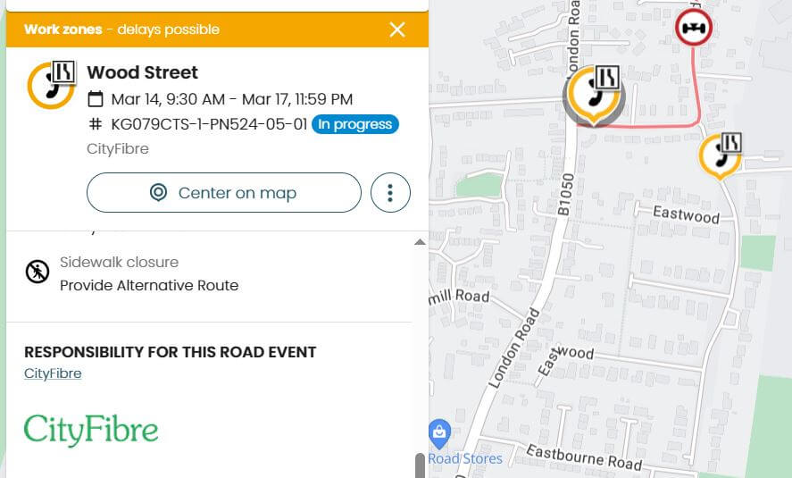
The above ASN example connects to the Primary Node directly, other pole mounted ASN’s have two connections, one In and the other Out to the next pole mounted ASN, in London Road for example 5 pole ASN’s are fed from the Primary Node using this method.
Depending of the ‘Cherry Picker’ crew fitting the ASN determines if the pole displays a warning sign, as I understand it, the sign is not mandated.
Stock image of a Cityfibre engineer splicing the incoming fibre to the Aerial Secondary Node.
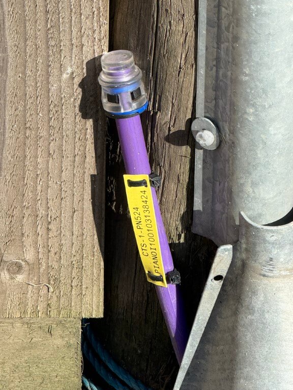
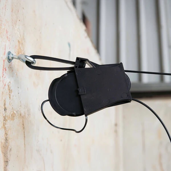
Connection from the pole to your property is via an overhead Dropwire, Cityfibre fibre dropwire is a round profile and uses a fibre drop clamp as below:
Netomnia use a flat profile fibre dropwire and therfore use a clamp reffered to as a ‘slippery fish’ :
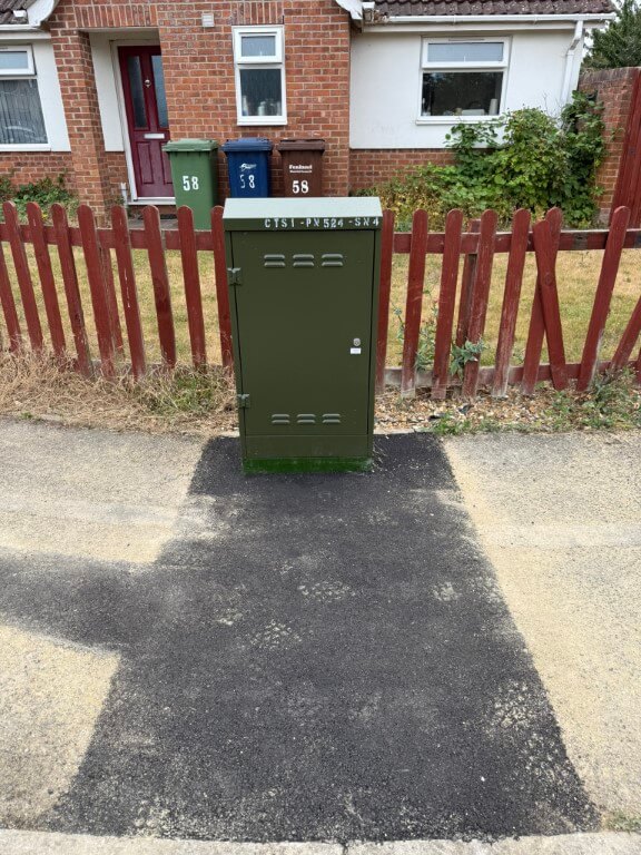
Secondary Node Cabinet.
Toby fitted in the pavement. (18 March 2025)
The significance of the ‘Toby’ is that Netomnia only provide a service using either or overhead cables from poles or using existing BT ducts to your house, this means houses which have no local poles or that have telephone cables which are ‘directly buried’ in the ground, can’t get a Netomina provided service from Youfibre.
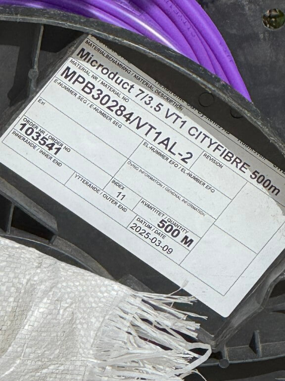
Microduct used to connect the Secondary Cabinet to the Toby
Fibre cable used from Primary Note to Aerial Secondary Node – Data Sheet
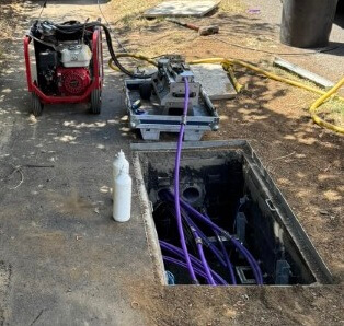
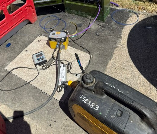
Fibre blowing equipment, the one on the left is blowing 432 core fibre whilst the one on the right is for smaller fibres.
Toby Box
Toby boxes are found in the pavement near your premises, or on a nearby pole as a drop wire. Toby boxes bring the connection from the Secondary Node to outside of your premises. When a network is built, this is where the connection stops until the customer signs up to connect their premises into the network.
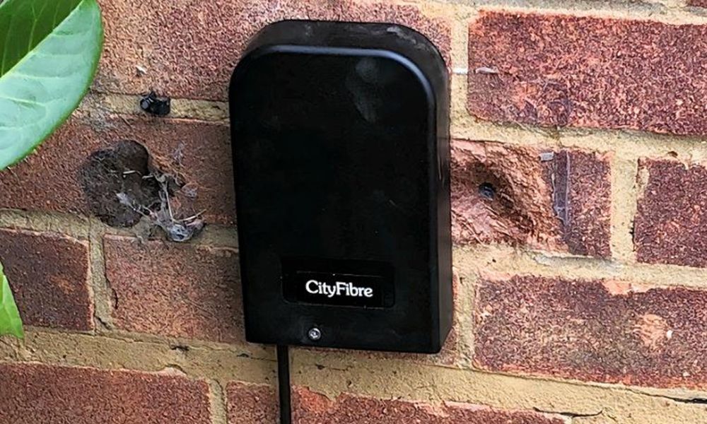
Wall Box
Connection is taken from the Toby Box on the pavement to a Wall Box (Termination Point) TP)) on the outside of your premises. This is installed when you sign up to a CityFibre network provider. The Wall Box then connects via a Lead In Kit to an Optical Network Termination (ONT) box inside of your premises, which in turn connects into the router. This process brings fibre optic connectivity all the way into your premises. You will need 2 power sockets, 1 to power the ONT and 1 to power your router.
New duct and Cityfibre manholes have been installed along the A141 taking extending service to Warboys, Old Hurst, Woodhurst, Pidley, Somersham, Colne, Earith and Willingham to name a few.
I noted a number of new poles have been installed by Cityfibre to take service connections to remote farms.
15 December 2025
Engineer ‘end to end’ testing a 288 fibre cable which belongs directly to a customer.
30 Jan 26 – Engineering testing works completed, cabinet identifier does not follow the normal Cityfibre broadband provision for cabinets, (possibly) confirming that it is a service for a customer who needs dedicated fibres, (5G mast or maybe another broadband provider like Hyperoptic ?).
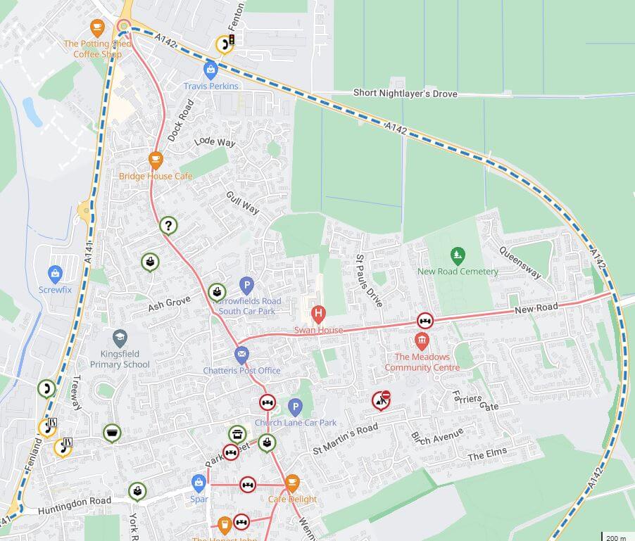
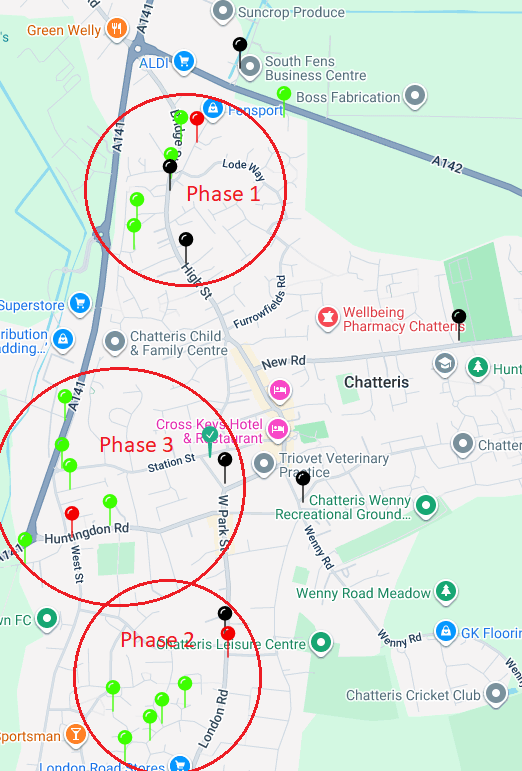
Cabinets Map
The Pin map shows the position of street cabinets, hovering over each pin will show its location and cabinet number, the see images of the cabinet, click the green circular cross below the map:
GREEN pins are Secondary Node Street Cabinets;
RED pins are Primary Node Street Cabinets;
BLACK pins are Spine Chambers;
GREEN TICK pins are Cabinets not yet completed;
RED CROSS pins denote photographs need updating.
The speed of installation and quality of restoration is an absolute testament to the hard working lads doing the job, especially considering the heat we are having.
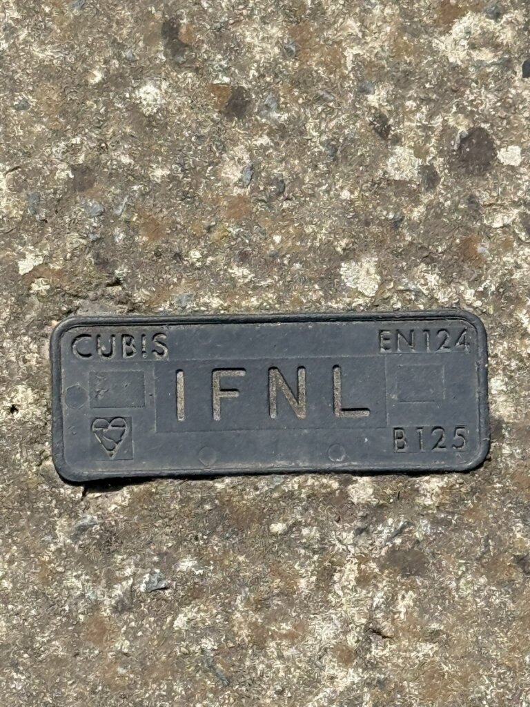
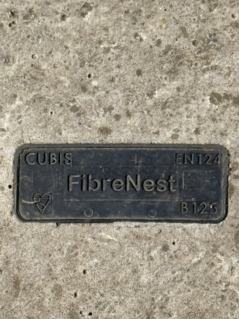
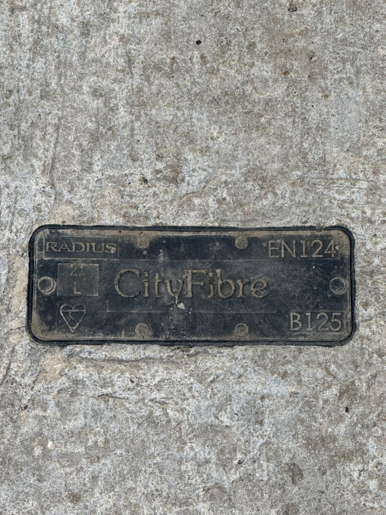
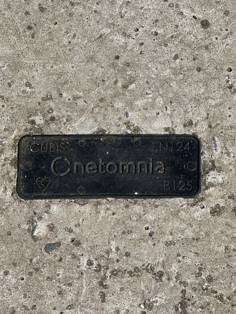
Above are fibre providers in Chatteris as of 2025, (CATV & IFNL are Vigin Media).
Kelly Communications Cityfibre Installation Platform is an engineers tool to ensure a smooth installation and customer experience, (the version is October 2023 so may not be the latest).
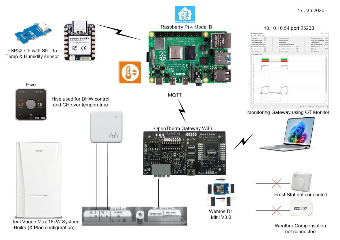
I have an Ideal Vogue Max 18kW System Boiler with Weather Compensation using a flow temperature of 50oC and using Hive to control the schedules and room temperature, I also have individual radiator Hive TRVs but these are set to 23oC to limit overtemperature, ideally the system is set to ‘open loop’ control with the Hall Thermostat controlling temperture.
As a Home Assistant user, I saw that a Smart Autotune Thermostat (SAT) integration was available which enabled Opentherm control of the boiler, rather than the Hive’s simple On/Off control.
The advantage of Opentherm control was predictive and tighter control leading to increased efficiencies when coupled with SAT.
The above is a simple overview of the revised boiler control.
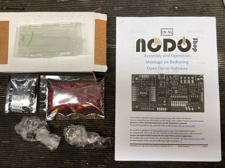
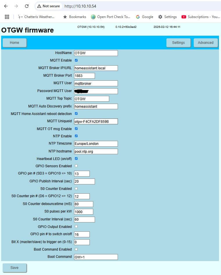
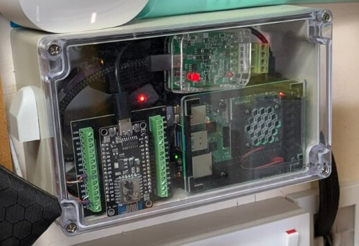
Opentherm Gateway(OTGW) – This build kit was bought from Nodo-Shop, I chose the Wi-Fi version and paid to have the WeMos D1 Mini Wi-Fi module pre-programmed, I also bought a case for the completed gateway.
Project links and construction details are at the bottom of this blog.
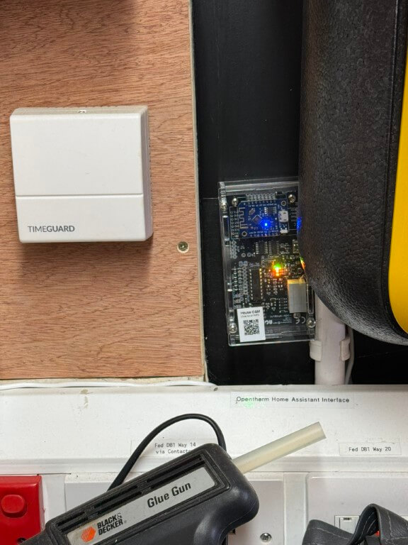
Completed NODO Opentherm/Home Assistant interface connected and working, I did initially have a problem with the build, in that I couldn’t get communications with the boiler, this was resolved with a new PIC chip.
The forum support and NODO shop were great, and had me up and running in no time.
Getting it to work –
On Home assistant I installed Mosquitto Broker Add-on to manage MQTT messages from the OTGW, to do this I followed tutorials on YouTube and set up additional Home Assistant (HA) user accounts for the MQTT broker and Client as directed.
The Smart Autotune Thermostat (SAT) integration was also downloaded and installed on HA.
As I bought a pre-programmed Wi-Fi module, all I had to do is power it up and use my mobile phone to find its Wi-Fi and set up the network details, after this I could find it on my network and add all the relevant MQTT details, once done, HA discovers it and everything worked magically for me.
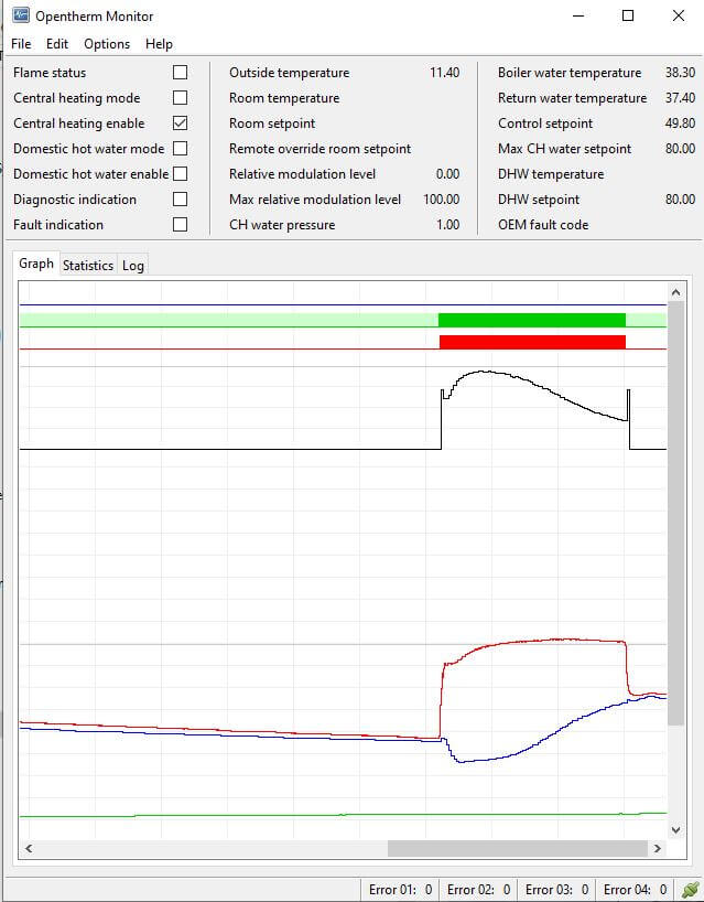
Now I knew the OTGW network IP address, I could connect to OM Monitor which reads the Opentherm traffic, in my case the boilers return water temperature was not being read for some reason, however, their are some real experts on the forums ever willing to share information and I was told to disconnect the Halo Lite thermostat which I had connected for testing purposes and miraculously all readings populated :-).
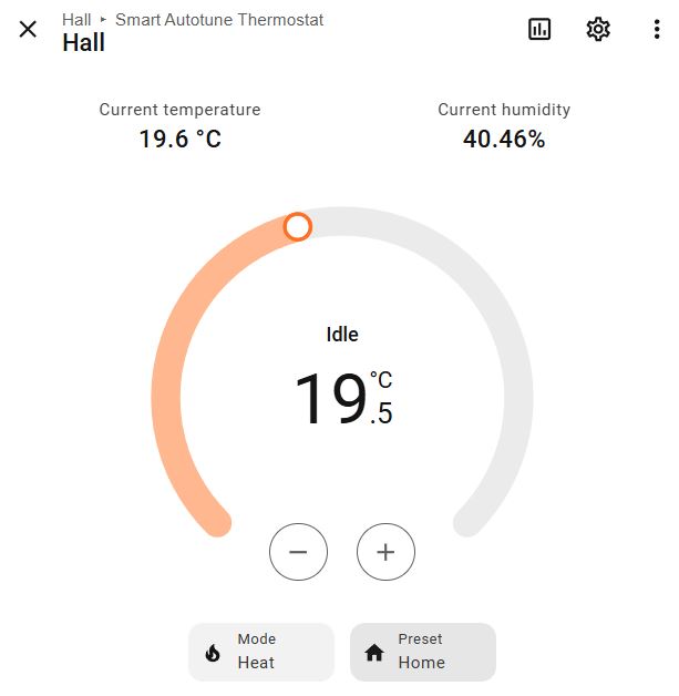
Hall Temperature Sensor
Hive is used for timing schedules for domestic hot water (DHW) with the central heating (CH) being left on 24hrs at 23oC, this is used as an overtemperature fallback control.
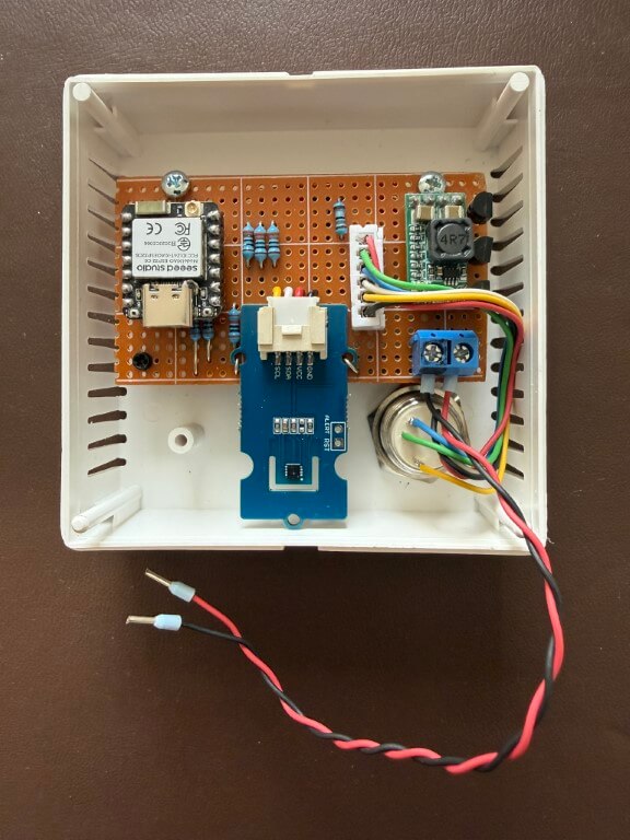
Home made replacement thermostat in a sensor housing from CPC is a SHT35 Temperature & Humidity sensor connected to an ESP32-C6, power is from a 12v PSU reduced to 5v with a buck converter.
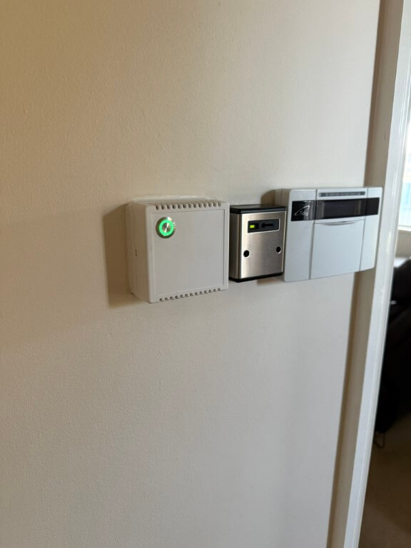
Temperature sensor mounted, the momentary push button has a RGB led, I have used green to indicate ‘Home’ setting, red for ‘Comfort’ setting and blue for ‘Away’ or setback.
Pressing the button will scroll through the options allowing for manual control, a further tweak is that the green led will flash if a non-preset temperature is selected on Home Assistant, also if the heating is off, no leds will be lit.
The leds also automatically dim at night.
Script used is at the bottom of the blog.
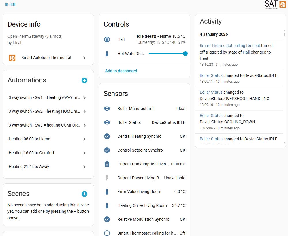
Home Assistant
My SAT has three heating periods set up, these are ‘Away’, ‘Home’ and ‘Comfort’, and are time controlled within the application:
Away – 21:45 to 06:00 setback temperature 17oC
Home – 06:00 to 16:00 temperature 19.5oC
Comfort – 16:00 to 21:45 temperature 21.5oC (sedentary)
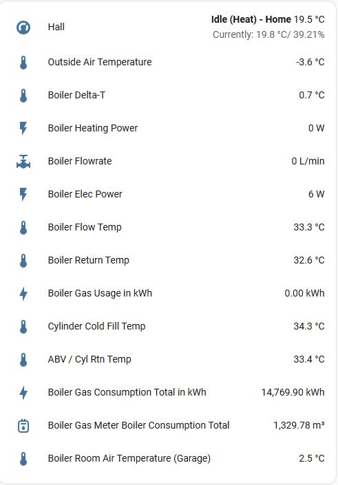
The dashboard displaying general details, this was screen grabbed when the external temperature was -3.6oC and the system is performing perfectly.
Raspberry Pi for Open Energy Monitor connectivity and also a ESP8266 for secondary gas meter measurement to boiler.
Interactive boiler layout.
Should it all go wrong
Hopefully it won’t, but if I ever need to revert back to conventional control, I simply need to remove the wires from boilers Opentherm connection and link the terminals, reconnect the weather sensor and thats it.
Learning-
The layout of the house lends itself to leaving all the internal doors open, therefore, the temperature is consistent throughout.
Ideal Halo Opentherm thermostat does not play nicely with the Opentherm Gateway.
The Timeguard frost stat is no longer connected to the boiler due to the fact that the central heating can only be brought on by the Opentherm gateway, therefore, I have to rely on the boilers inbuilt frost protection, this measures the boilers internal return pipe, if this falls to 5oC, the boiler will fire up until the return reaches above 19oC, however, the Timeguard is now connected to a Shelly Mini, so that I get notification of low temperature in the garage where the boiler is located.
A blog about stuff that interests me or I have done.
We use cookies on our website to give you the most relevant experience by remembering your preferences and repeat visits. By clicking “Accept All”, you consent to the use of ALL the cookies. However, you may visit "Cookie Settings" to provide a controlled consent.
This website uses cookies to improve your experience while you navigate through the website. Out of these, the cookies that are categorized as necessary are stored on your browser as they are essential for the working of basic functionalities of the website. We also use third-party cookies that help us analyze and understand how you use this website. These cookies will be stored in your browser only with your consent. You also have the option to opt-out of these cookies. But opting out of some of these cookies may affect your browsing experience.
Necessary cookies are absolutely essential for the website to function properly. These cookies ensure basic functionalities and security features of the website, anonymously.
Cookie
Duration
Description
_GRECAPTCHA
5 months 27 days
This cookie is set by the Google recaptcha service to identify bots to protect the website against malicious spam attacks.
cookielawinfo-checkbox-advertisement
1 year
Set by the GDPR Cookie Consent plugin, this cookie is used to record the user consent for the cookies in the "Advertisement" category .
cookielawinfo-checkbox-analytics
11 months
This cookie is set by GDPR Cookie Consent plugin. The cookie is used to store the user consent for the cookies in the category "Analytics".
cookielawinfo-checkbox-functional
11 months
The cookie is set by GDPR cookie consent to record the user consent for the cookies in the category "Functional".
cookielawinfo-checkbox-necessary
11 months
This cookie is set by GDPR Cookie Consent plugin. The cookies is used to store the user consent for the cookies in the category "Necessary".
cookielawinfo-checkbox-others
11 months
This cookie is set by GDPR Cookie Consent plugin. The cookie is used to store the user consent for the cookies in the category "Other.
cookielawinfo-checkbox-performance
11 months
This cookie is set by GDPR Cookie Consent plugin. The cookie is used to store the user consent for the cookies in the category "Performance".
CookieLawInfoConsent
1 year
Records the default button state of the corresponding category & the status of CCPA. It works only in coordination with the primary cookie.
PHPSESSID
session
This cookie is native to PHP applications. The cookie is used to store and identify a users' unique session ID for the purpose of managing user session on the website. The cookie is a session cookies and is deleted when all the browser windows are closed.
viewed_cookie_policy
11 months
The cookie is set by the GDPR Cookie Consent plugin and is used to store whether or not user has consented to the use of cookies. It does not store any personal data.
Functional cookies help to perform certain functionalities like sharing the content of the website on social media platforms, collect feedbacks, and other third-party features.
Performance cookies are used to understand and analyze the key performance indexes of the website which helps in delivering a better user experience for the visitors.
Analytical cookies are used to understand how visitors interact with the website. These cookies help provide information on metrics the number of visitors, bounce rate, traffic source, etc.
Cookie
Duration
Description
_ga
2 years
The _ga cookie, installed by Google Analytics, calculates visitor, session and campaign data and also keeps track of site usage for the site's analytics report. The cookie stores information anonymously and assigns a randomly generated number to recognize unique visitors.
_ga_92TJCVGJP2
2 years
This cookie is installed by Google Analytics.
_gat_gtag_UA_48800884_1
1 minute
Set by Google to distinguish users.
_gid
1 day
Installed by Google Analytics, _gid cookie stores information on how visitors use a website, while also creating an analytics report of the website's performance. Some of the data that are collected include the number of visitors, their source, and the pages they visit anonymously.
CONSENT
2 years
YouTube sets this cookie via embedded youtube-videos and registers anonymous statistical data.
is_unique
5 years
StatCounter sets this cookie to determine whether a user is a first-time or a returning visitor and to estimate the accumulated unique visits per site.
is_visitor_unique
2 years
StatCounter sets this cookie to determine whether a user is a first-time or a returning visitor.
sc_is_visitor_unique
2 years
StatCounter sets this cookie to determine whether a user is a first-time or a returning visitor.
Advertisement cookies are used to provide visitors with relevant ads and marketing campaigns. These cookies track visitors across websites and collect information to provide customized ads.
Cookie
Duration
Description
NID
6 months
NID cookie, set by Google, is used for advertising purposes; to limit the number of times the user sees an ad, to mute unwanted ads, and to measure the effectiveness of ads.
VISITOR_INFO1_LIVE
past
A cookie set by YouTube to measure bandwidth that determines whether the user gets the new or old player interface.
YSC
session
YSC cookie is set by Youtube and is used to track the views of embedded videos on Youtube pages.
yt-remote-connected-devices
never
YouTube sets this cookie to store the video preferences of the user using embedded YouTube video.
yt-remote-device-id
never
YouTube sets this cookie to store the video preferences of the user using embedded YouTube video.
yt.innertube::nextId
never
This cookie, set by YouTube, registers a unique ID to store data on what videos from YouTube the user has seen.
yt.innertube::requests
never
This cookie, set by YouTube, registers a unique ID to store data on what videos from YouTube the user has seen.


