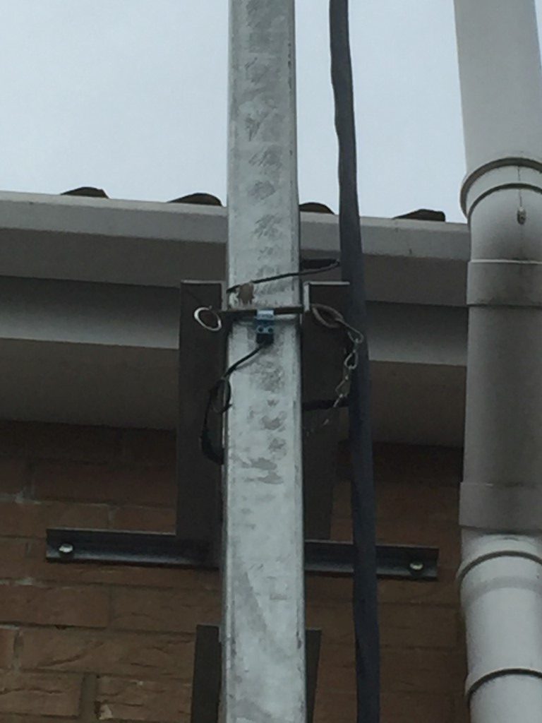
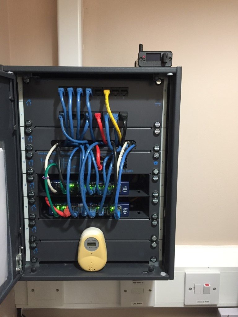
I used to have a PC on 24/7 running weather software linked to my weather station, this allowed me to have a relay operate should the wind speed exceed a predifined value, this would then signal my antenna mast to automatically retract.
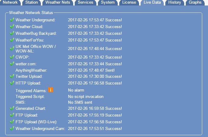
To save energy, I no longer use a PC to publish weather station data to the internet and once this was switched off I lost the relay facility, so I needed a solution.
Looking for windspeed switches on the Internet kept pointing to commercial units at £320 ish, however, I did stumble accross this link from Geeky Gadgets for an Arduino based unit which looked perfect for my needs and all credit must go to the author.
Key Parts
Mouser Electronics:
Anemometer part# 485-1733 @ £42.62
eBay:
LCD Keypad Sheild 2 x16 display 1602 @ £5.75
Arduino Uno @ £8.95
Relay unit @ £0.99
Total Cost £58.31
Construction was very simple, it involved plugging the LCD sheild onto the Arduino, uploading the sketch and making the three connections from the anemometer to the Arduino.
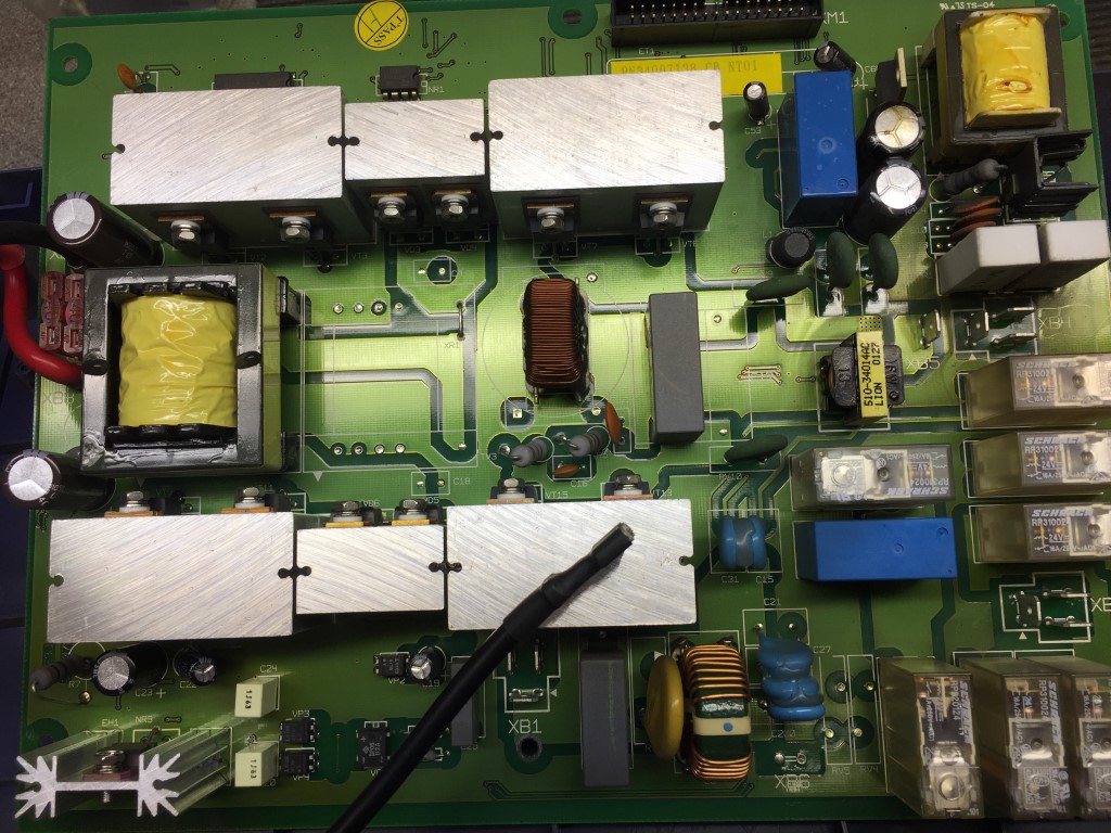
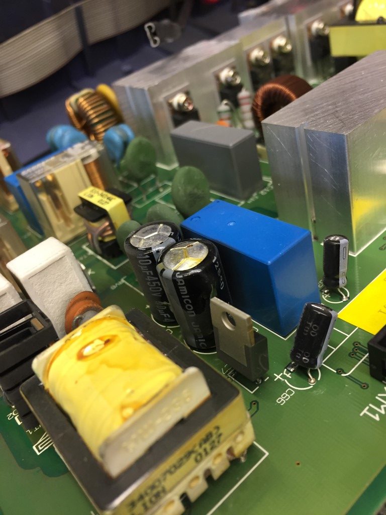
The connection information is in the Geeky Gadgets documentation with the exception of the relay output, the picture below shows this.
Things to note:
- The contrast pot on the LCD sheild may need to be adjusted to give an optimal display.
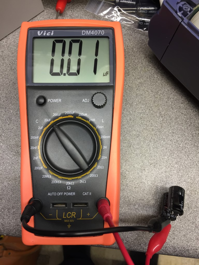
- The ‘standstill’ mV of the anemometer needs to be measured and entered in the sketch (min was 0.4345 mV) so the display shows 0 MPH at rest. This is done with a digital voltmeter to measure the resting output, or you could use trail and error and enter values in the sketch until zero MPH is registered, and then slowly increment the values, uploading each time a change is made, until you hit a point where a speed is registered, then back the number down, at this point you should see and increase in speed displayed with minor turning of the cups.

The above is the finished setup, just ready to mount in a suitable enclosure, for test purposes I have set the relay to operate at 4 MPH, when the speed drops below this, the relay de-energises.
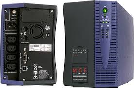
The finished unit will be powered by 12v and will work as a standalone unit with a simple normally open output to the mast automation PLC.
Arduino Software can be downloaded from HERE , the working sketch which allows a replay to operate if the windspeed exceeds a preset value is below, simply copy and paste the code below into Aduino software and save the file before compiling:
===================================================
/*
Arduino Wind Speed Meter Anemometer mph – Adafruit anemometer (product ID 1733).
Modified code created March 2016 from original code created by Joe Burg 11th November 2014
At http://www.hackerscapes.com/ with help from Adafruit forum user shirad
12 Feb 17 added relay output based on wind speed.
*/
//Initialise LCD display
#include <LiquidCrystal.h>
LiquidCrystal lcd(8, 9, 4, 5, 6, 7);
int serial_in;
int relay =3;
//Setup Variables
double x = 0;
double y = 0;
const int sensorPin = A1; //Defines the pin that the anemometer output is connected to
int sensorValue = 0; //Variable stores the value direct from the analog pin
float sensorVoltage = 0; //Variable that stores the voltage (in Volts) from the anemometer being sent to the analog pin
float windSpeed = 0; // Wind speed in meters per second (m/s)
float voltageConversionConstant = .004882814; //This constant maps the value provided from the analog read function, which ranges from 0 to 1023, to actual voltage, which ranges from 0V to 5V
int sensorDelay = 2000; //Delay between sensor readings, measured in milliseconds (ms)
//Anemometer Technical Variables
//The following variables correspond to the anemometer sold by Adafruit, but could be modified to fit other anemometers.
float voltageMin = 0.4345; // Mininum output voltage from anemometer in mV.
float windSpeedMin = 0; // Wind speed in meters/sec corresponding to minimum voltage
float voltageMax = 2.0; // Maximum output voltage from anemometer in mV.
float windSpeedMax = 32; // Wind speed in meters/sec corresponding to maximum voltage
void setup()
{
//Setup LCD display with welcome screen
lcd.begin(16,2);
lcd.print(“Geeky Gadgets”);
lcd.setCursor(0,1);
lcd.print(“Windspeed Sensor”);
delay(2500);
lcd.clear();
lcd.setCursor(0,0);
Serial.begin(9600); //Start the serial connection
pinMode(relay,OUTPUT);
}
//Anemometer calculations
void loop()
{
sensorValue = analogRead(sensorPin); //Get a value between 0 and 1023 from the analog pin connected to the anemometer
sensorVoltage = sensorValue * voltageConversionConstant; //Convert sensor value to actual voltage
if (sensorVoltage <= voltageMin){ windSpeed = 0; //Convert voltage value to wind speed using range of max and min voltages and wind speed for the anemometer. Check if voltage is below minimum value. If so, set wind speed to zero.
}else { windSpeed = ((sensorVoltage – voltageMin)*windSpeedMax/(voltageMax – voltageMin)*2.23694); //For voltages above minimum value, use the linear relationship to calculate wind speed in MPH.
//Max wind speed calculation below
x = windSpeed; if (x >= y){
y = x;
}else
y = y;
}
//Print voltage and windspeed to serial
Serial.print(“Voltage: “);
Serial.print(sensorVoltage);
Serial.print(“\t”);
Serial.print(“Wind speed: “);
Serial.println(windSpeed);
//Display Wind Speed results to LCD with Max wind speed
lcd.setCursor(0,0);
lcd.print(“Wind Speed mph”);
lcd.setCursor(0,1);
lcd.print(windSpeed);
lcd.setCursor(7, 1);
lcd.print(“Max=”);
lcd.setCursor(11, 1);
lcd.print(y);
if (windSpeed >4) { //Enter the value of MPH windspeed to be exceeded which will operate the relay
digitalWrite(3,HIGH);
} else{
digitalWrite(3,LOW);
}
delay(sensorDelay);
}
===================================================
For my purposes the displayed wind speed does not have to be calibrated, I only need an indicative reading, therefore cannot vouch for accuracy of this unit.