Shack Clock Modification

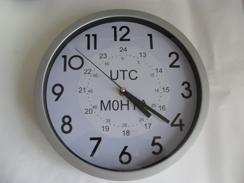
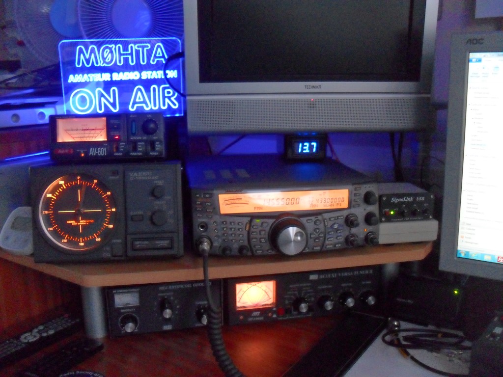
The clock in my shack is one of those which receives a radio signal enabling it to be constantly accurate and it will automatically adjust for British Summer Time, as the contact time in paper and electronic logs is recorded in UTC (Coordinated Universal Time), I decided to get an additional  conventional analogue wall clock and customize it a little.

SAM_5394 (Medium)

The battery powered clock used was described as a kitchen wall clock, item code 257946  costing £3.99 from B&M’s.

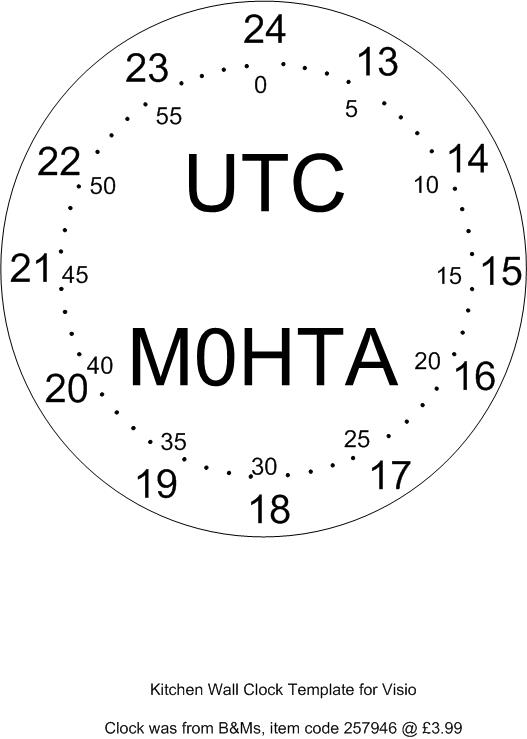
I wanted the clock to show 24 hour format, that it was in UTC and my call sign, I decided to print the detail onto 80gsm paper, printing a circular cutting line and stick the addition to the clock face.

I used Visio for the drawing and the template can be downloaded here, a jpg version for editing in paint is here.

The clock came apart by the removal of a few screws, the hands were then removed, the clock mechanism was held in place with a nut, once removed the disassembly was complete.

The printout was cut, and adhered to the clock face with a ‘Prit stick’ type glue and the clock reassembled, job done!

If I had a working colour printer I would have highlighted some of the new detail and maybe even added a picture, but the cost of printer ink is didn’t warrant the expenditure on this little project.

The clock face on the clock I used was slightly over A4 size, if it was less than A4, I would have printed a completely customized new face so no difference in contrast would be seen.

First Australian Receive of M0HTA

I have posted previously about a distant contact logged using the program WSPR using 10 watts, for this Australian contact my transceiver was using the 30m band, mode USB with an output from the rig set to 5 watts.

prog

After the PC clock has been synchronized to the network, I run the software which is linked to my transceiver via serial COM port 1, selecting the chosen band, the software adjusts the transceiver to the correct frequency and will then receive and decode signals, before waiting a pre determined time, before transmitting my station call sign, QRA locator and power output.

Whilst my station is transmitting, other stations who are running WSPR are in listening mode and I’m listening for their signal when I’m not transmitting, this allows a map of interconnections of, I can hear them, they can hear me or both.

oz

I couldn’t believe that within an hour of running the program my signal was received in Australia, up until that point it was mostly Europe which was to be expected, I left the program running for12 hours in total, and the map shows where I had contacted in that time.

Completed Crowbar Circuit Build

Link to Crowbar Circuit Part 1 which has the circuit diagram and part list.

The last part of the project was to mount the circuit in the enclosure, I also bought a panel mounted digital voltmeter which is really useful.

Unit sat on top of the TS-2000 displaying the voltage.

Internal views of the unit, I have modified the board from that shown in Part 1 by the addition of a fuse holder mounted on the veroboard, this has a 2A slow blow fitted and protects the non terminal post outlets.

SAM_5389 (Medium)

SAM_5388 (Medium)

SAM_5386 (Medium)

SAM_5385 (Medium)

SAM_5384 (Medium)

SAM_5383 (Medium)


Kenwood TS-2000 Footswitch PTT via SignaLink Interface

Latest Version – Modified 14 June.

I’m slowly building up my station and thought that a foot operated ‘Push to Talk’ (PTT) would be a good addition, the switch I bought was an Eagle Electronics G028B Momentary foot switch with 6.35mm plug, this is a type used by musicians so is very robust and was bought from Juno Records for £8.41 inclusive of postage, delivery was within 2 days.

SAM_5374 (Medium)

The G028B came with a 6.35mm mono jack plug, this was removed and replaced with a 2.5mm jack as the socket which is used later has a smaller footprint than a large jack socket.

The rig has two connections where it is possible to operate the PTT, the first is the microphone socket on the front of the rig, the other is using a connection available from ACC2 at the rear of the rig.

I was looking at a way of breaking into one of these cables in order to make the connection to the footswitch when I thought of using the SignaLink box as a breakout.

signalink (Medium)

The SignaLink is connected to the ACC2 socket on the rig using a cable marked SLCAB13K, the connection into SignaLink is an 8 wire RJ45 plug.

The connections are (Refer to page 95 of the Kenwood  instruction manual for ACC2 pin functions):

  1. RJ45 SignaLink    3-Kenwood ACC2
  2. RJ45 SignaLink    11 -Kenwood ACC2
  3. RJ45 SignaLink    9-Kenwood ACC2
  4. RJ45 SignaLink    13-Kenwood ACC2
  5. Not connected
  6. RJ45 SignaLink    4-Kenwood ACC2
  7. RJ45 SignaLink    8-Kenwood ACC2
  8. RJ45 SignaLink    12-Kenwood ACC2

The existing SignaLink configuration links for my rig was:

  1. SPK
  2. MIC
  3. PTT
  4. —  Use this to connect to Footswitch and 8.G to operate PTT
  5. G
  6. G
  7. G

The unconnected pin 4 from the RJ45 is connected to pin 13 on the rig, this allows the PTT to operate and NOT disconnect the Mic.

SAM_5367 (Medium)SAM_5368 (Medium)

I left enough lead on the footswitch socket so it will thread through the SignaLink enclose without taking the socket apart.

Removing  jumper 8 out of the holder, strip a small section of insulation and solder the flying leads to the outer of the 2.5mm footswitch socket, returning the jumper to the same position as it was removed from, for the  inner connection of the 2.5mm socket a wire was inserted into he empty number 4 socket on the side nearest the RJ45 socket.

SAM_5379 (Medium)

SAM_5372 (Medium)

This turned out to be a quick, cheap and neat workaround rather than hack into cables or adding additional plugs and sockets to make a breakout.

All done and working in under an hour,  the footswitch is ‘press to make’ it does not need to be left plugged in, so can be put out of the way until needed.

Hope this was useful.

Blitzortung Station Ident Changed

Due to a user error (me), I inadvertently blew the Blitzortung STM32F4-Discovery daughter board, fortunately this was the only element damaged.

The new station identification number is now 1354 from the previous ident of 755, the original station was 675 but after each daughter board change, the station is reassigned a new number based on the embedded code within the discovery board.

I was off line for about two hours, but everything is working as expected again.

Crowbar Overvoltage Circuit to Protect Transceiver

NOTE – Thanks to Stewart (G0LGS), no consideration was given to the current carrying capacity of the veroboard tracks,  which turns out to be just under 6A, so, if you are going to make this, please bear that in mind.

I was looking for a simple circuit to protect my radio  and auxiliary equipment  from overvoltage and found a circuit diagram and full description amongst other useful projects on Phil Salas – AD5X site – www.ad5x.com/articles.htm.

The voltage protector file including circuit diagram and full parts list is available for downloadable here – Vprotect.

The circuit is designed to ‘blow’ the supply fuse to the equipment in order to protect it, the protection is from reverse polarity as well as  transient spikes and damaging overvoltage.

The specification for the Kenwood TS-2000 is 13.8v +/- 15% ( Total Maximum voltage 15.87v), this circuit will only allow 14.8v to pass before the protection crowbar circuit operates.

The components are sizes for 40A, the Kenwood maximum current draw is 20.5A, so well within capacity.

SAM_5357 (Medium)

SAM_5358 (Medium)

The circuit board could have been made marginally smaller, but I was too lazy to trim it down!

vero board

Data Sheet for ThyrisorSAM_5360 (Medium)

This shows the test setup with the power supply units (PSU) current trip set low in order to monitor the tripping voltage, on the left of the PSU in between the knobs marked CURRENT, their is a small LED with C.C. for Constant Current, the circuit is working passing 13.73v to the meter.

SAM_5362 (Medium)

The voltage from the PSU has now been increase past the crowbar limit of 14.8v and the C.C LED is ON showing that if this was a fuse it would have operated to protect the transceiver, 14.8v is the maximum voltage that will ever reach the transceiver, no matter what!

Parts: – These were from UK ebay

1.5KE 15 TVS Diode 1.5KW 15v DO-21 – £1.69

Thyristor 40A, 600v TO-220 TYN640RG – £3.19

IN5245B Diode Zener 15v 0.5w – £1.42

Radial Electrolytic Capacitor 1uF 50v – £0.99

Resistors 27k, 10 Ohm and Veroboard I had already

Less than £8 to protect an expensive radio, filtered speaker etc. pictures of completed unit is HERE.