
After completing and passing the radio amateur foundation licence test, I have decided to undertake the Intermediate licence training with the hope of gaining this Licence, as part of the syllabus the construction of a project is required, the project used within the ‘Intermediate Licence – Building on the Foundation’ book (£8.94 inc postage from www.rsgb.org) shows a Variable Frequency Oscillator (VFO).
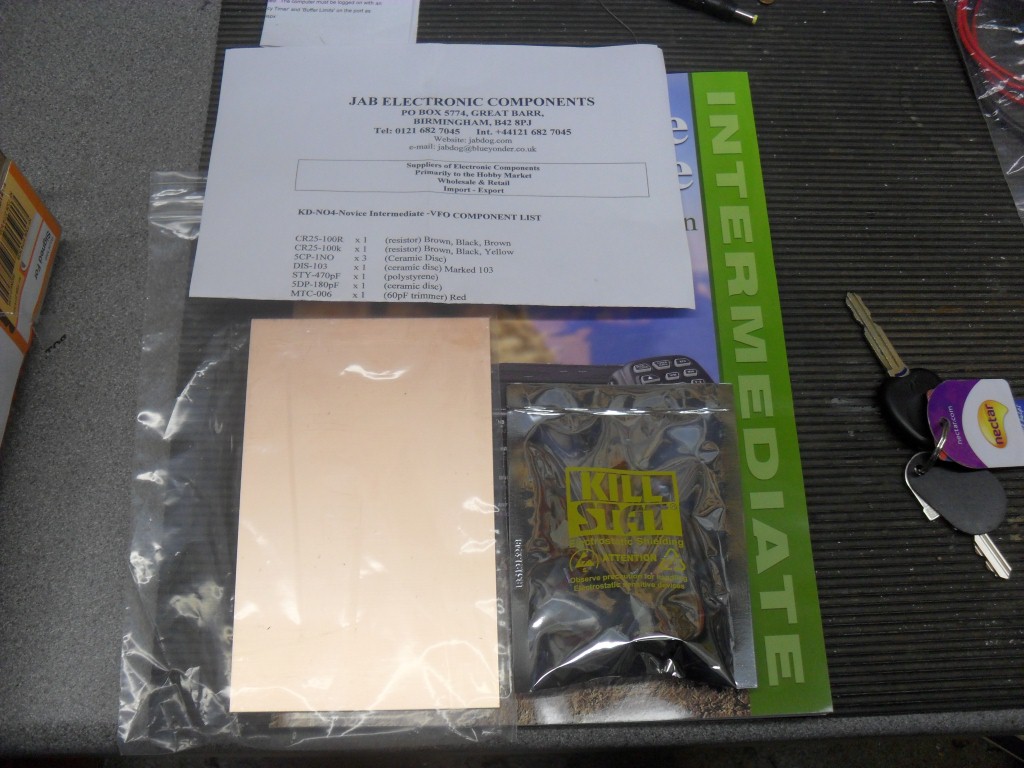
I sourced the kit through JAB Electronic Components (www.jabdog.com), the kit cost £12.95 inc postage and I must say the level of customer service was exceptional, I can highly recommend this vendor.
The kit contains all the parts to construct the VFO, a parts list comes with the kit, but the wiring schematic is in the Foundation book and was therefore not included in the kit, also you will need a 9v pp3 battery (or equivalent) and assembly tools.
The kits form part of the structured learning at radio clubs for those undertaking the foundation course, as I have experience of electronic construction, I made and tested the unit at home, but will use the kit as evidence in meeting the syllabus requirements.
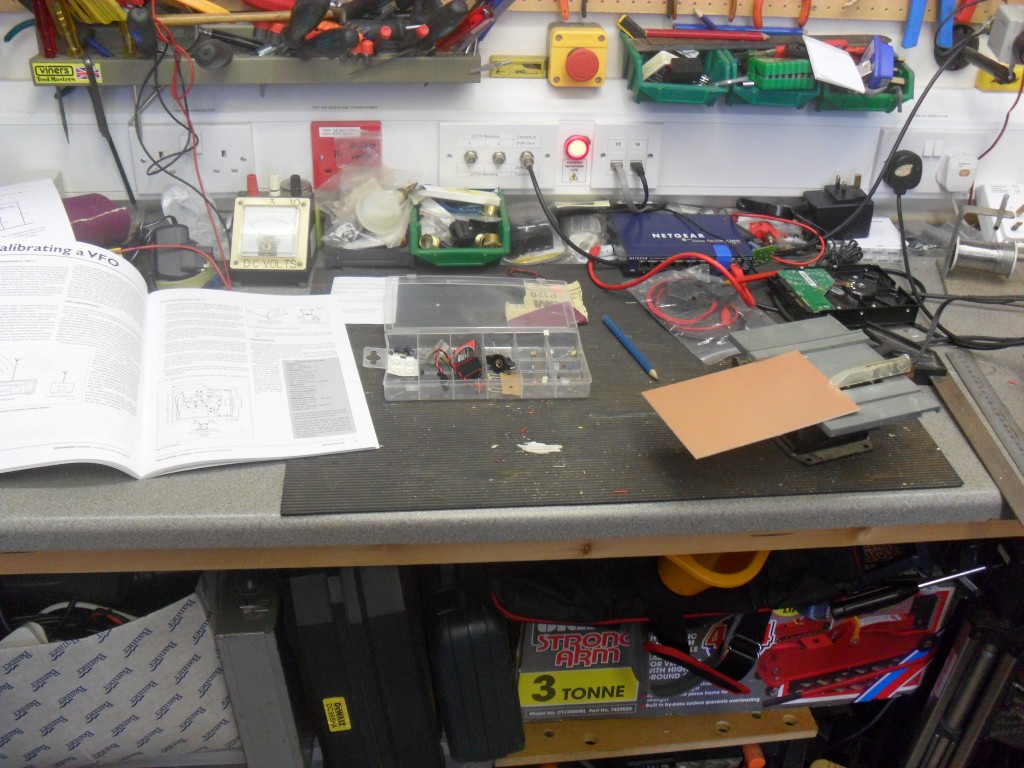
The Parts came the next day, with the fist task of checking-off the components and sorting them into the partitioned bit box:
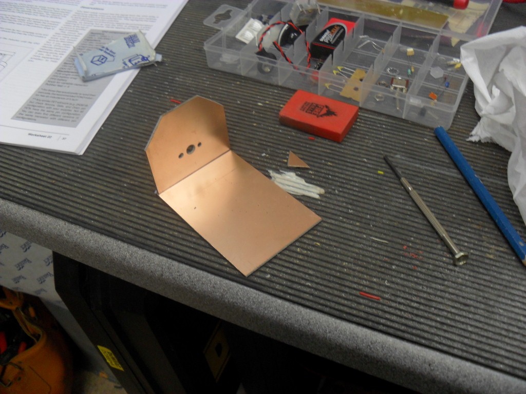
Once all was in order the dimensions for the board was 60cm x 90cm, I did have a 12v powered table saw for cutting of printed circuit boards, it did manage to cut this board but it was a struggle, a hacksaw would have been quicker:
Once the base was cut, the front panel for the variable capacitor needed to be cut, the top of the front panel has the edges cut off at 45 degrees, this cut material is not wasted, it is used to give the front panel mechanical support, prior to soldering, I used blue tack to hold the front panel in place, to ensure a good soldered joint, I use a pencil eraser to clean the copper board of oxide before applying heat.
The front panel is now mechanically secure and so I could mount and solder in the variable capacitor, the kit does not include fixing machine screws, I found some screws taken from a laptop when it was being disassembled which were the correct fit which was lucky as the screws are tiny:
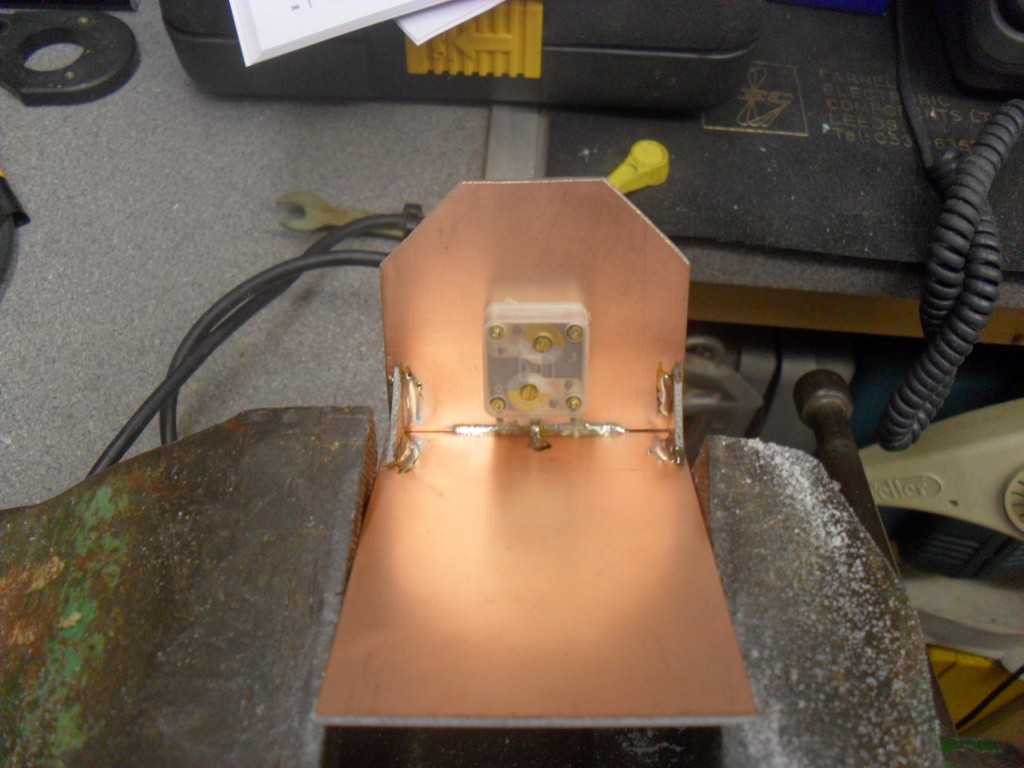
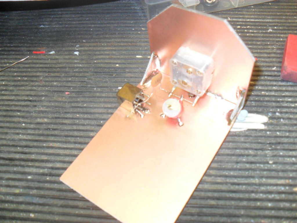
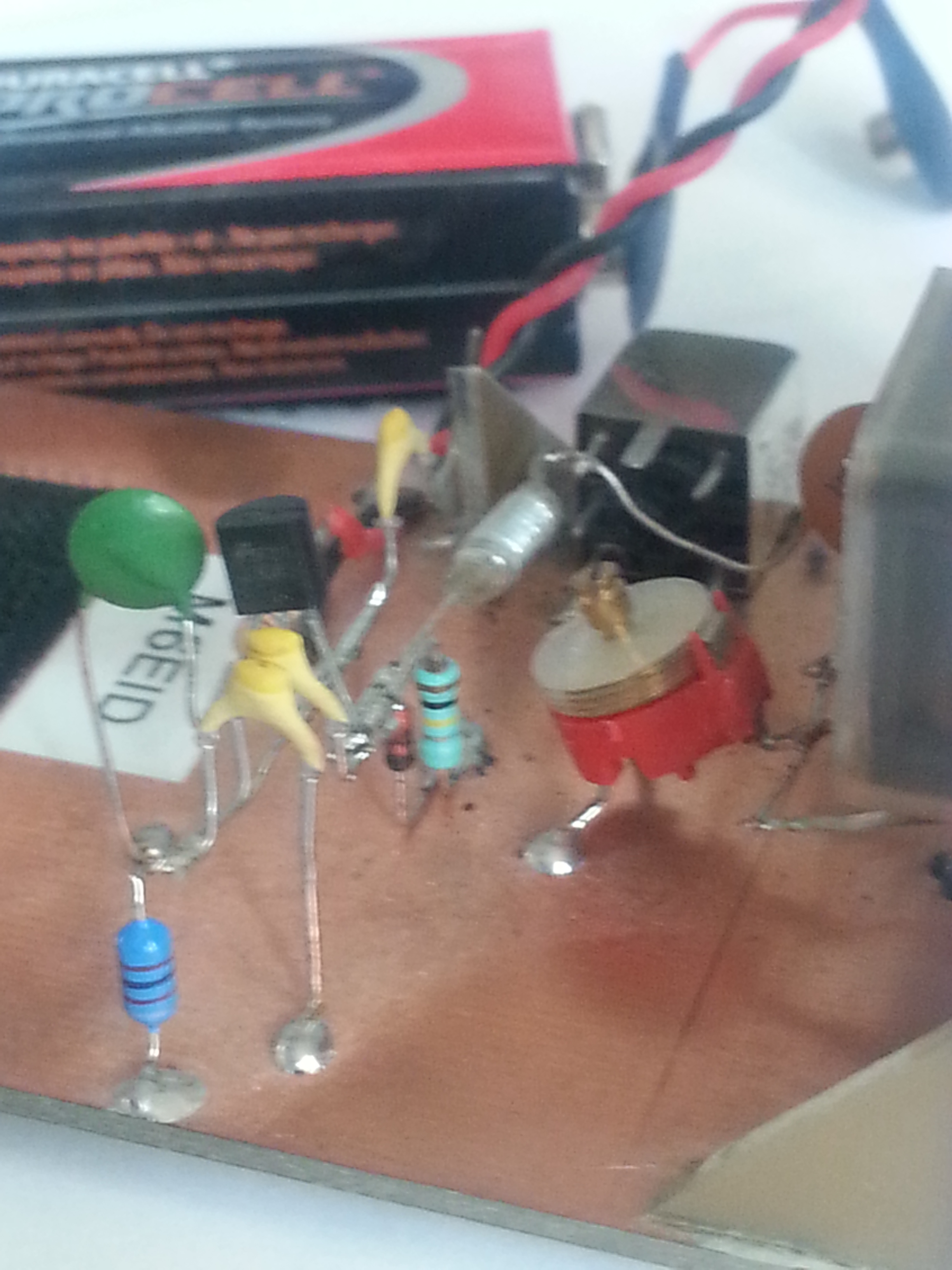
The trimmer and capacitor were next soldered in, to the left of the picture is the KANK variable inductor which was the next component to get soldered in, the positioning of this was dependant on the length of the capacitors lead, I wanted to minimise any additional wiring, so where possible I used the component leads and jointed other components from these:
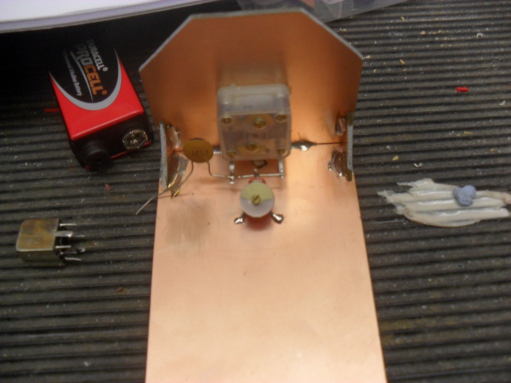
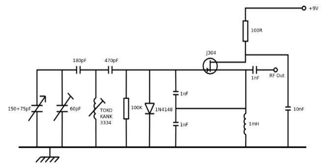
Once the inductor was in place, this gave the run for the other components, I did not follow the layout diagram (fig 43: VFO Layout) in the foundation book as I found it easier to use circuit diagram, which I found on the internet from South Bristol Amateur Radio Club, this will assist any fault finding at a later stage should it be needed.
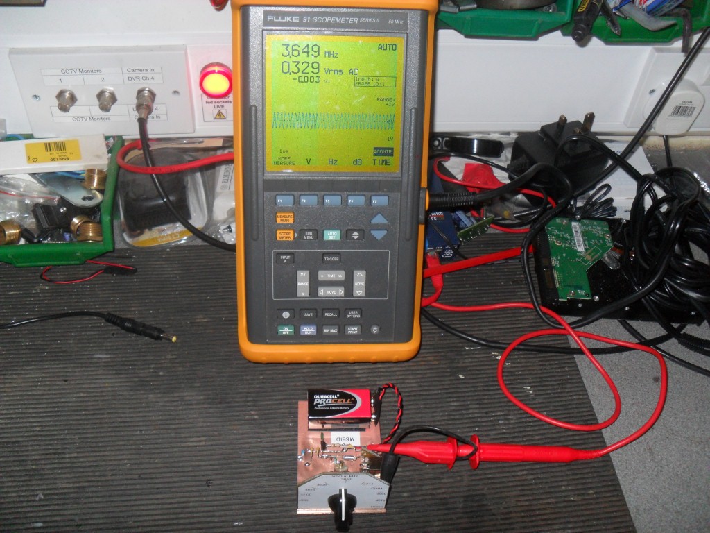
With all parts soldered in place I used Velcro to hold the battery in place, as this was a test piece I did not incorporate an on/off switch. Prior to powering up I checked all the connections were sound and that components were correctly fitted, using a Digital Volt Meter set on the mA range in series with the circuit, I applied the battery terminal and checked the load, 8mA was being drawn, so all was well.
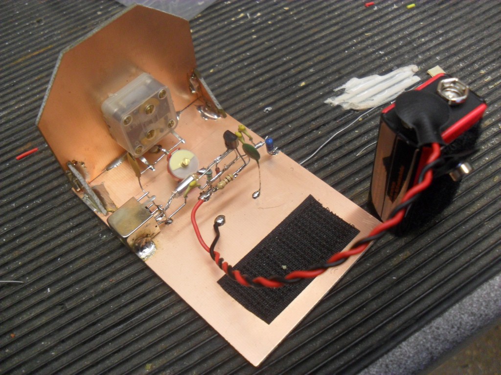
Final stage was to secure the battery leads to the board by passing a cable tie through drilled holes, the RF out connection needed some support as test leads would be clipped to this, I used an off-cut and soldered it to the baseboard and then to the output wire ensuring that I had broken the copper etch using a hacksaw. I linked the VFO to my scope to calibrate for operation and once proved working, roughly calibrated the front scale.
All that was left was to put the ‘sticky feet’ on the base and that was it!
(Big thank you to Andy (G6OHM) for offering to vouch that this was all made by my own fair hands :-))
Updated 3 April 16
I have added a number of images which offer better clarity of how things are soldered together, certain images above now have a hover over zoom enabled as well.

Thank you for this guide.
I am 76, and whilst I trained as a Radio Technician with Royal Signals I last looked at the inside of a radio in 1960… And have never looked at anything electronic in the intervening years.
In those days it was all galvanised chassis, ‘hard-wiring’ and valves etc. and it all weighed a ton!
I have never used PCB before nor any of the ‘micro’ type components in the Jabdog kit, so your guide will be very very useful.
Thanks too for the link to the Bristol Club.
With luck and some effort I might just get my Intermediate, and that all important 50w!!
73
Robert
Hi Robert,
I’m glad you found it useful, I’ve every confidence that you will pass the intermediate and wind that power up a bit 🙂
Hi this is very helpful.
Could you explain the wiring of the trimmer to the varicap, and also the Kank. All components have multiple nodes, not the two in the schematic.
Thanks in advance,
David M6WHF
Hi David,
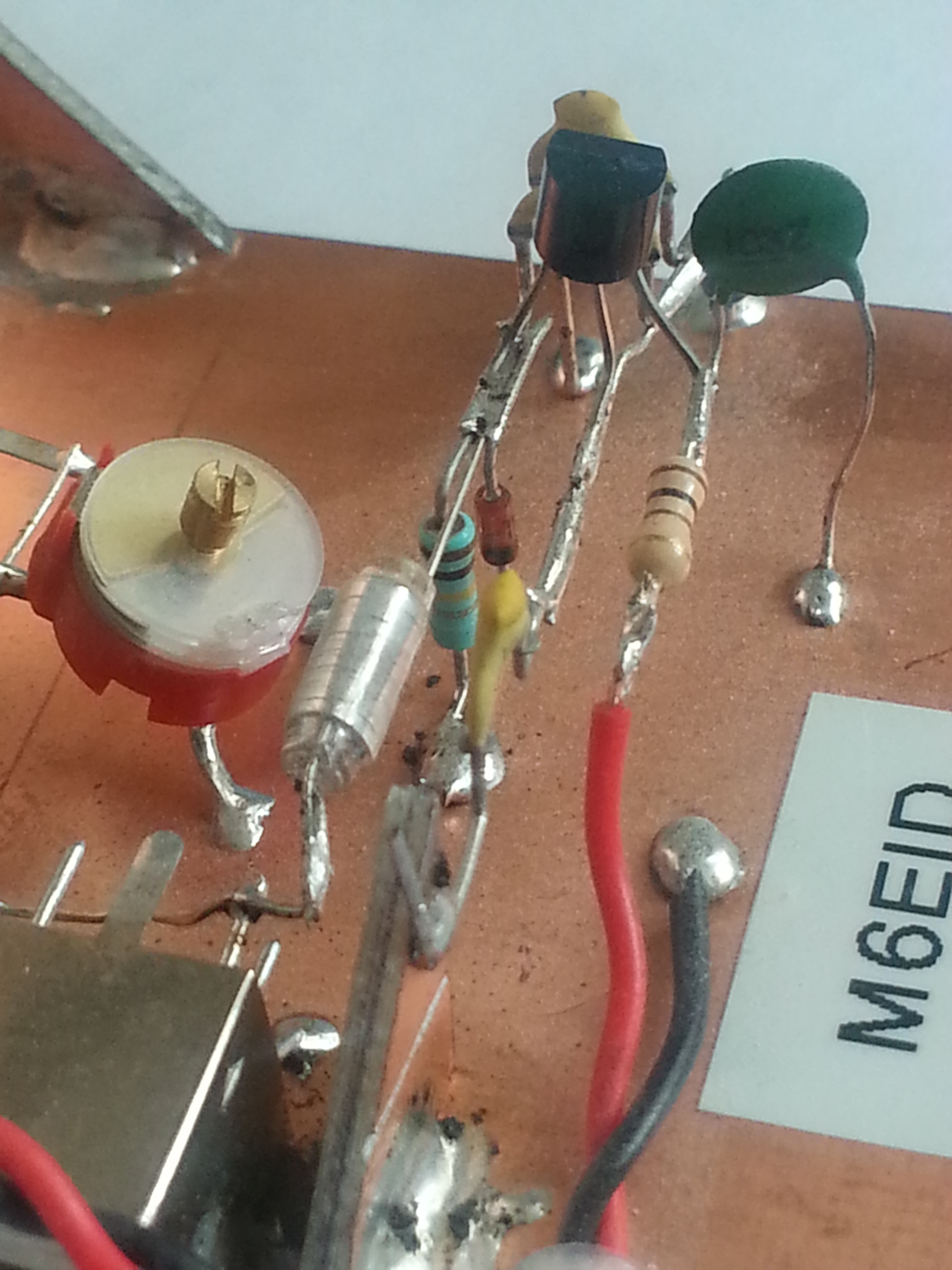
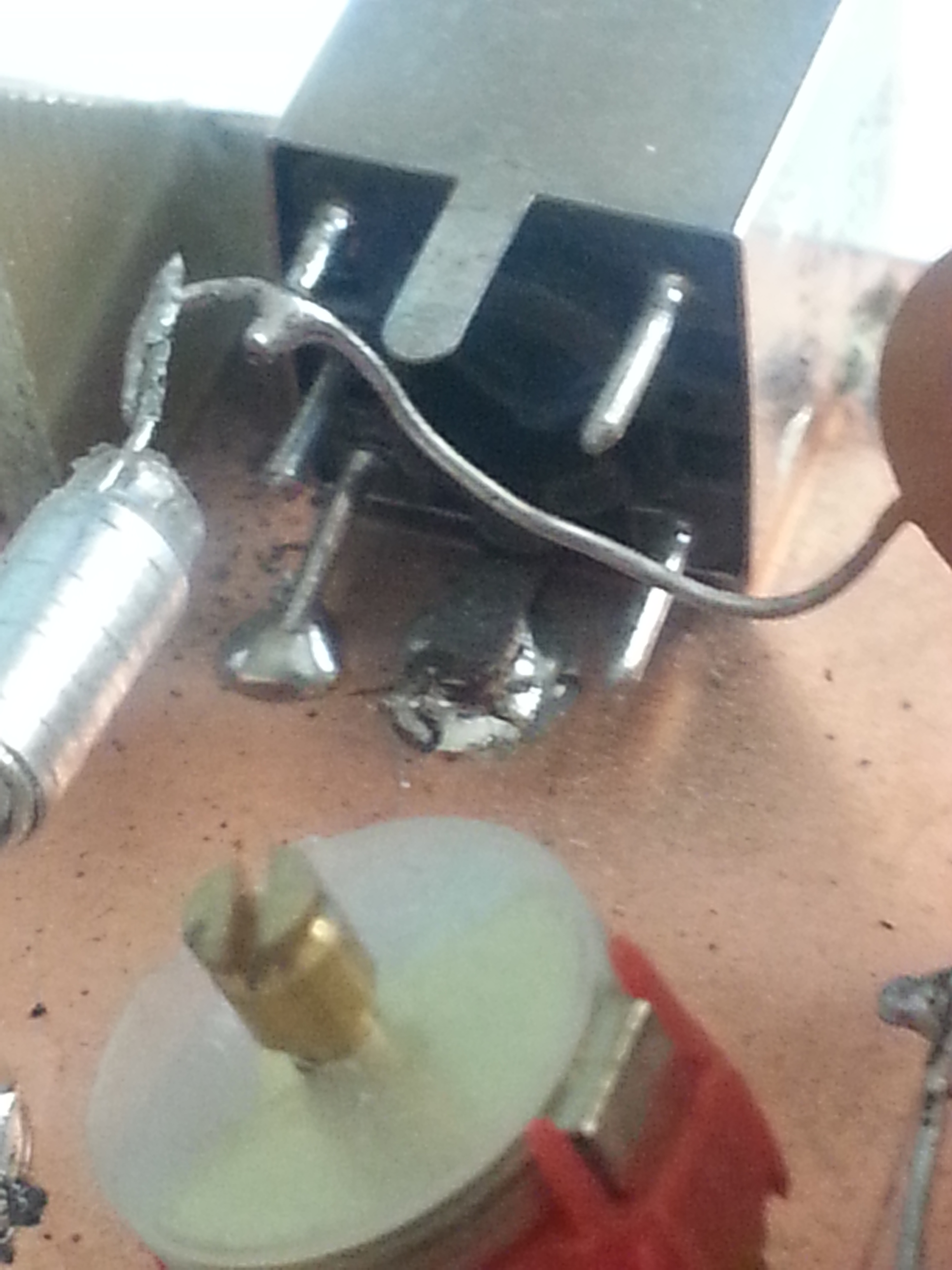
I have added a few more pictures which better illustrate the connections used, in order to find the appropriate connections I used an inductance and capacitance meter.
Good luck and best wishes for the exam.
A very helpful guide – especially the pictures. Thank you. Rik