Intruder Alarm Circuit Test Box

I thought I’d build a test box which will simulate the three circuit conditions of an intruder detection system (IDS), these being:

  • Circuit Tamper
  • Alarm Condition
  • Circuit Healthy or Closed (non alarm condition)

The purpose was to confirm and test the ’cause & effect’ programming of a Pyronix Euro 46 panel , the Euro 46 remote Upload/Download Software allows for logic gates to be configured, so the system ended up being very versatile.

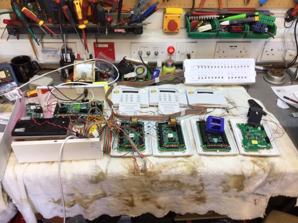
The above picture shows the Euro 46, Keypads, Zone Expansion, Output and Wireless modules set up for testing using the multiswitch test box, the alarm system is communicating with the Pyronix Cloud server via a LAN interface, cloud configuration also allows seamless integration with the Hikvision CCTV system.

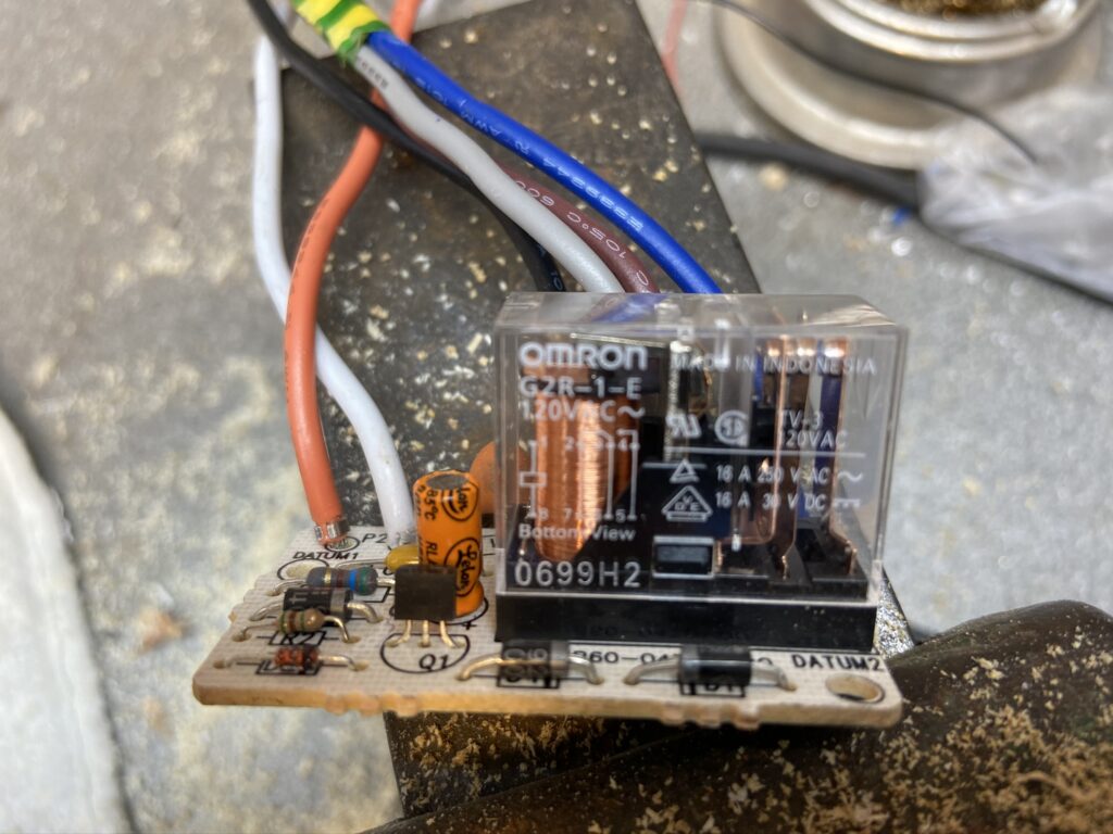
The Euro 46 has several detection circuit configurations, I chose the common value for a Double End Of Line resistor system of a 2k2 and 4k7 Ohms.

At the detection input a healthy or closed circuit, would measure a resistance value of 2k2 Ohms, if the value either exceeded or fell below this by a defined margin, the alarm panel would see this as a tamper condition, and alarm condition would present a value of 4k7 Ohms, the test box achieved the three conditions listed using the following diagram:

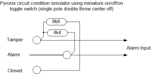
The above circuit presents to panel with slightly more resistance than 2k2 when healthy, however, as its within the parameters, the panel see’s this as closed with no faults.

The completed unit was built using 30 switches and I utilised an old piece of trunking to fit them in:

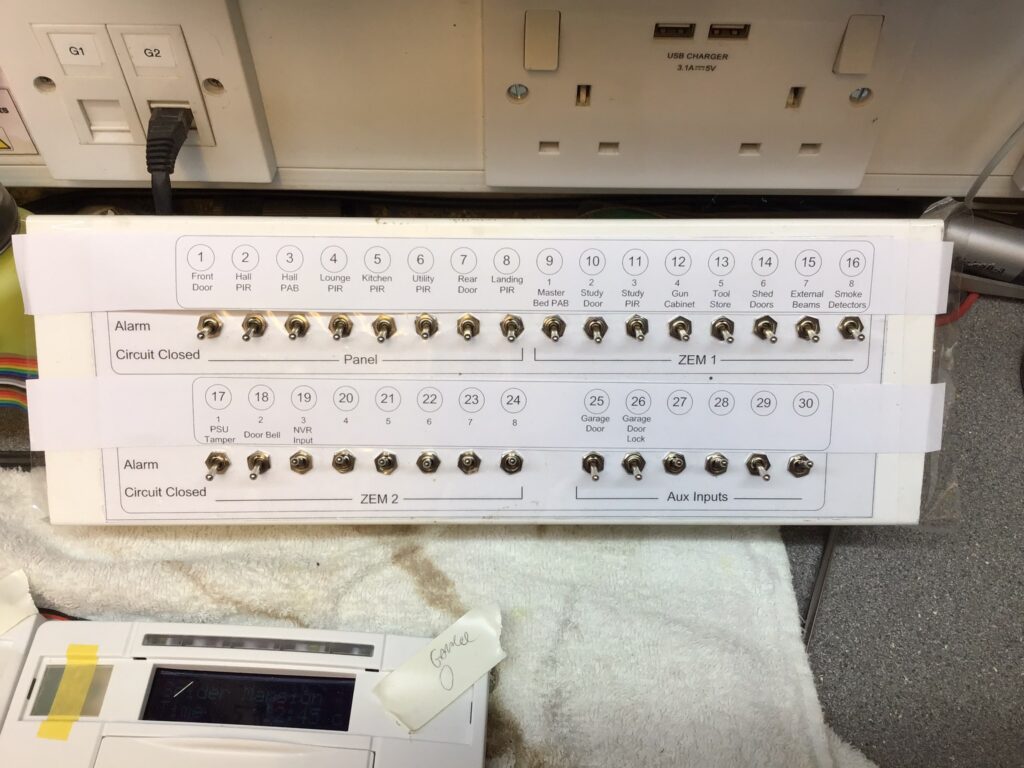
The circuit description label temporarily sticks over the laminated switch backing so I can fully program and test the wired circuits before installation in the future, one element I can’t test is the wireless aspect which forms a a large part of this system.

BRK Smoke Alarm Relay Interface

I have a number of BRK Smoke and Heat detectors which are interlinked to all sound on activation of any detector, I needed a way of linking the detectors to my house alarm which in turn would alert me on the mobile app.

A quick Google search flags a BRK RM4 relay interface which is triggered by the interconnect wire, the problem is they are only for the US market and work at 120v AC, this was confirmed with a phone call to the UK BRK representative.

I decided to take a punt and bought a RM4 from a US vendor, this took ages as a large number of seller just wouldn’t entertain shipping to the UK.

The moment the RM4 arrived, it was cut open 🙂

After checking the component data sheets the only parts which needed upgrading were the 2.2uF capacitor from 50v to 250v and the relay from 120v AC to 240v AC (part 369-337: G2R-2 230v).

Before swapping the parts I set up a ‘rough and ready’ test rig using a variostat to provide 110v AC to the RM4, a clamp meter was used to measure RM4 consumption and a 9v battery ready to place a voltage on the interconnect wire simulating an alarm condition, this worked fine.

After exchanging the capacitor and relay the RM4 was back on the rig and the supply voltage gradually increased to 240v AC while keeping a close eye on the current consumption which slightly increased from 2.8mA to 3.3mA.

The interface works as expected and the relay energises when a voltage is on the interconnect wire, it must be noted that the interface requires a supply voltage for it to work, the relay will not work in a power outage.

Sorry, bit of a messy picture, the RM4 is powered via the Rheostat with a ‘clamp on’ ammeter monitoring current draw and multimeter displaying the input voltage to the RM4, the PP3 9v battery was to simulate an trigger on the ‘Interconnect’ signal wire.

The RM4 wires are coloured for the US market and required sleeving with UK colours:

  • RM4 Relay White wire = UK Blue Neutral
  • RM4 Relay Black wire = UK Brown Live
  • RM4 Relay Orange wire = UK BRK White Interconnect