The Acronis True Image 2013 backup software in online ‘real time’ mode has caused me some problems since the 28th May when I enabled it, with the Weather Display application hanging and therefore generating a Clientraw data received error on the web site. I have reverted back to incremental backups every 24 hours, bit of a shame that the backup software won’t work as advertised (plenty of user comments on this when googled), but at least this method works.
Monthly Archives: May 2014
Weather PC Enhancements
Weather PC RAM increased from 2Gb to 4Gb due to memory resource issues when running Acronis back-up software in ‘real time online’ mode, this memory increase has resolved the problem and now instead of making Incremental backups once per day, the system is creating a constant mirror of the ‘C’ drive to the second hard drive which has also been made bootable.
Hopefully these resilience measures will not be needed, but if history does repeat itself I’m better prepared than last time.
Weather Station Down For Maintenance
Sorry for the interruption to the weather service, I needed to add a second hard drive and clone it, read too much lately of hard drive failures and decided to replace my existing second drive with a new one, rather than a refurbished one off ebay.
Chatteris weather was offline for 3 hrs 42 min, but I did make some changes as well, such as the clouds page, added a radio player to the marine page and also repaired a broken link with the alerts rss feed.
Added more information to Ham infrastructure

Added more info and photos to Ham Infrastructure blog.
Weather Station Update
Weather station has been behaving until a few days ago when it stopped receiving data from the Davis console, only confirmed this earlier today when Weather Display flat-lined, removing the mini usb from the consoles data logger and refitting it enabled Weather Display to start receiving data, checking the loggers drivers with Silicon Labs, the version I was using was not the latest, this has now been downloaded and seems to be working, I’ve no idea why this has just started so I’m not convinced that I have solved anything, fingers crossed 🙂
Sorry for the breaks in service.
Started on Ham Infrastructure
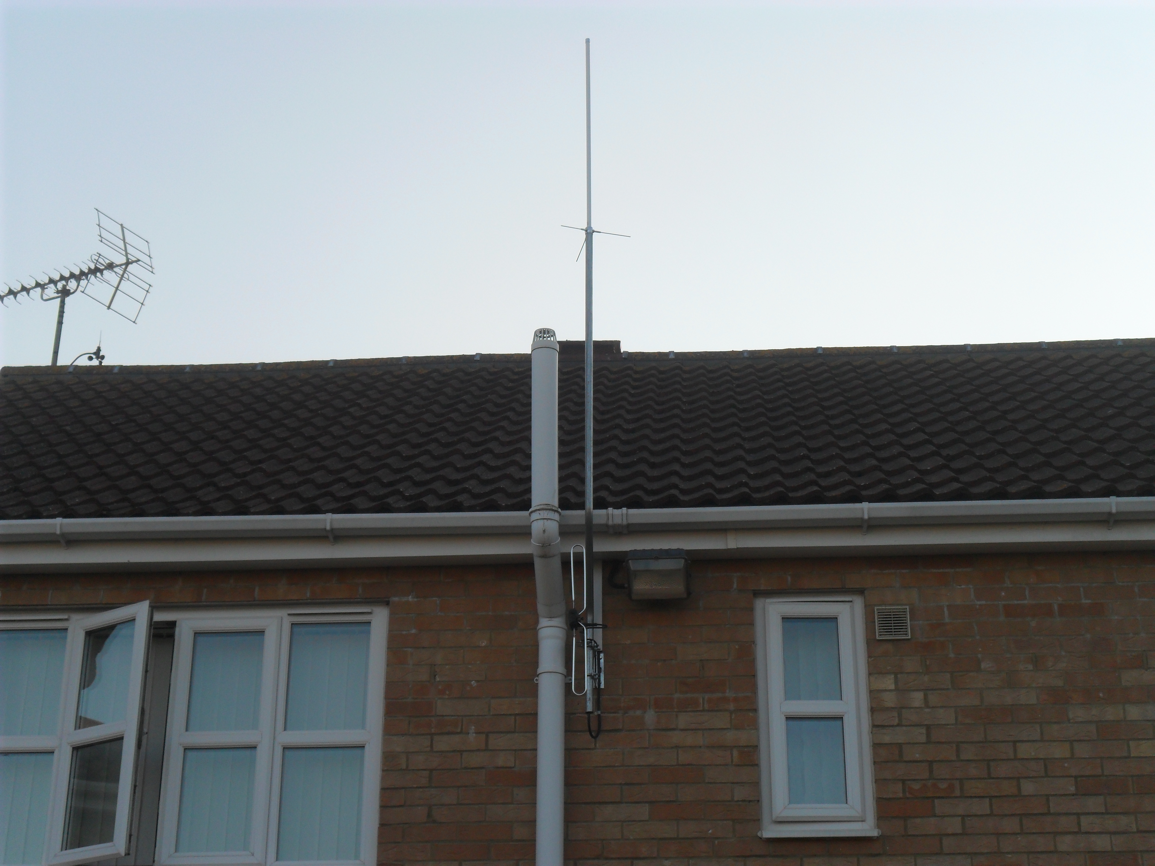
After a bit of surfing I decided on installing a Diamond x30 antenna, this has been fitted to a 9′ cranked offset pole, I have mounted this next to the soil vent stack so that the bracket and supporting pole are partially obscured from my immediate neighbour on my right, that said, the assembly doesn’t look that bad and cable management in the form of 50 x 25 trunking dropping from the soffit blends in somewhat.
I used RG213 cable, this will terminate in a double gang faceplate housing 3 x SO259 sockets, one socket is for the x30, one will be for a spare outlet in the loft and third will go to an external aerial which I have yet to decide on, cable routes have been found to outside down the cavity so that it ends a neat install, this route will also carry the stations RF earth.
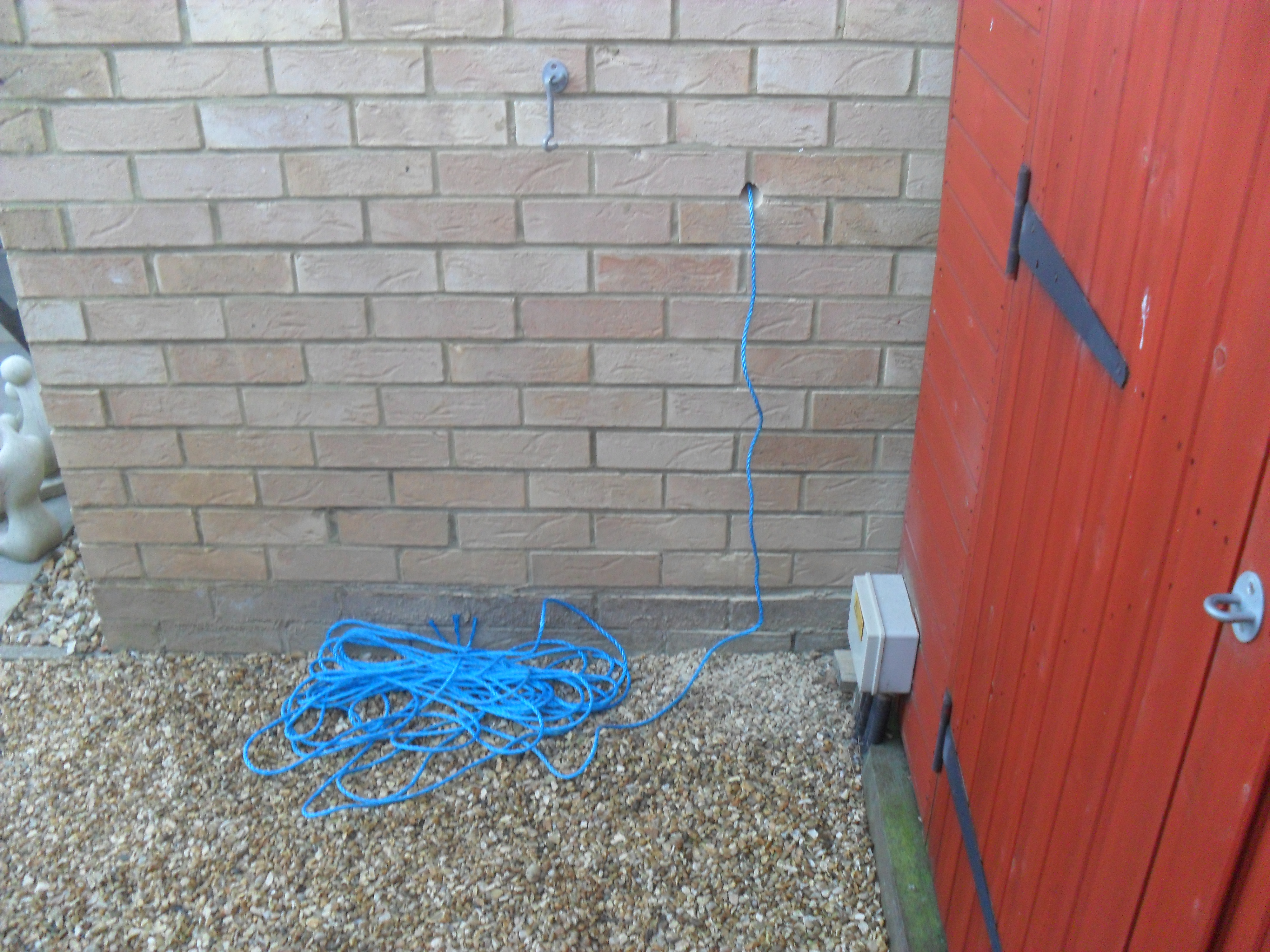
This shows the draw cord disappearing into the cavity ending up in the loft, I used a 30mm core bit at an angle of about 60 degrees to make the hole in the wall, once drilled, I used two lengths of 16mm trunking lid fixed together to get the right length to push up through the wall insulation. Fishing the trunking lid out in the loft is a two person job and a used a walkie-talkie with my better half, to get at this in the loft meant I had to take half a breeze block out as well as the skin off the back of my hand!, once captured, I affixed the draw cord and pulled the trunking lid out, pulling the cord down the cavity.
First wire to be drawn into the loft was an 6 core 7/02mm signal cable, this is looped out at the breakout faceplate and will allow me to add peripherals such as RF relay, rotators or powered equipment.
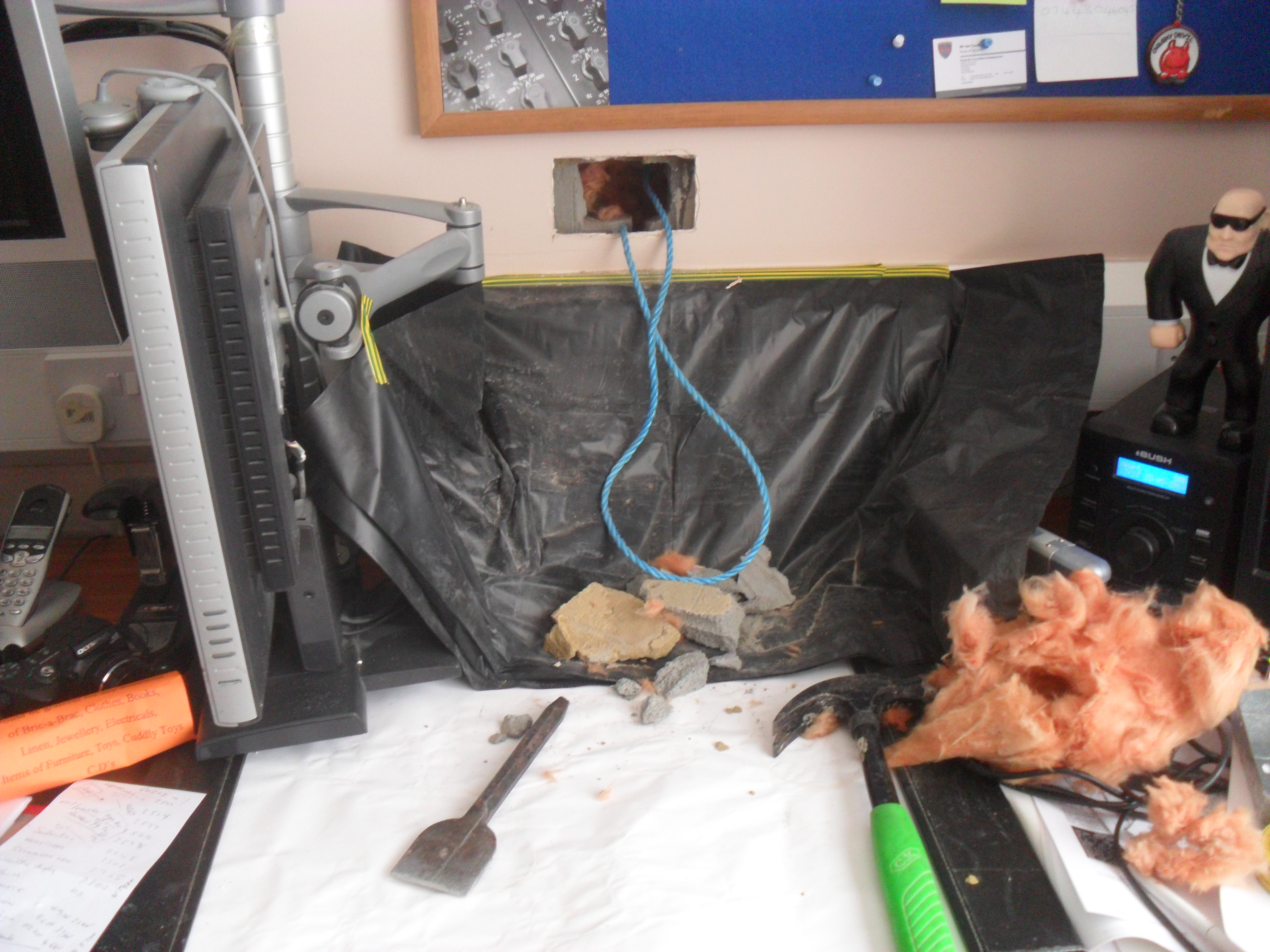
As my walls are ‘Dot and Dab’, meaning that the breeze block walls instead of being directly plastered, have blobs of plaster board fixing cement all over the place with the plaster board sheets being pressed against this and levelled, the board is then given a finishing skim of plaster, to make sure you don’t make a hole directly over a blob of fixing cement, tap the board with your hand and you will hear the sound change form ‘hollow’ to ‘solid’ as you work your way around the area of interest, if you have no option but to make your hole where it sounds solid, good luck!, I found a hollow spot in the region where I knew the draw cord was in the cavity, marking round a double metal backbox, I kept scoring the plasterboard with a utility knife until the cut board came out exposing the breeze block, using a 8mm drill bit, I chain drilled and then opened the hole with a bolster chisel. Using a brazing rod with a hook formed in the end, I managed on the forth attempt to hook the draw cord.
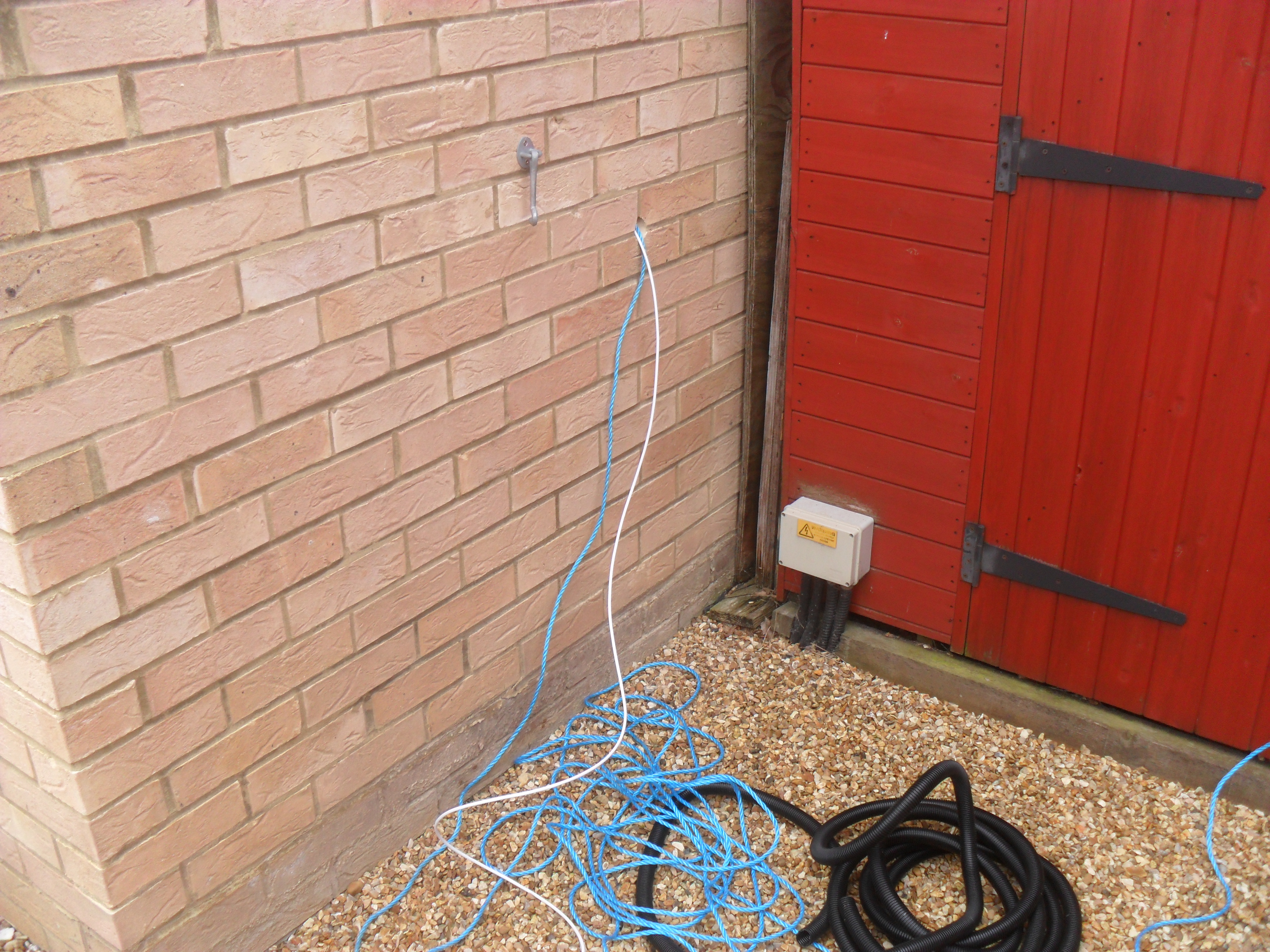
The image shows the RG213 from the x30 antenna and the longer RG213 which has been pulled up from outside, this will be looped, and pulled into the loft space.
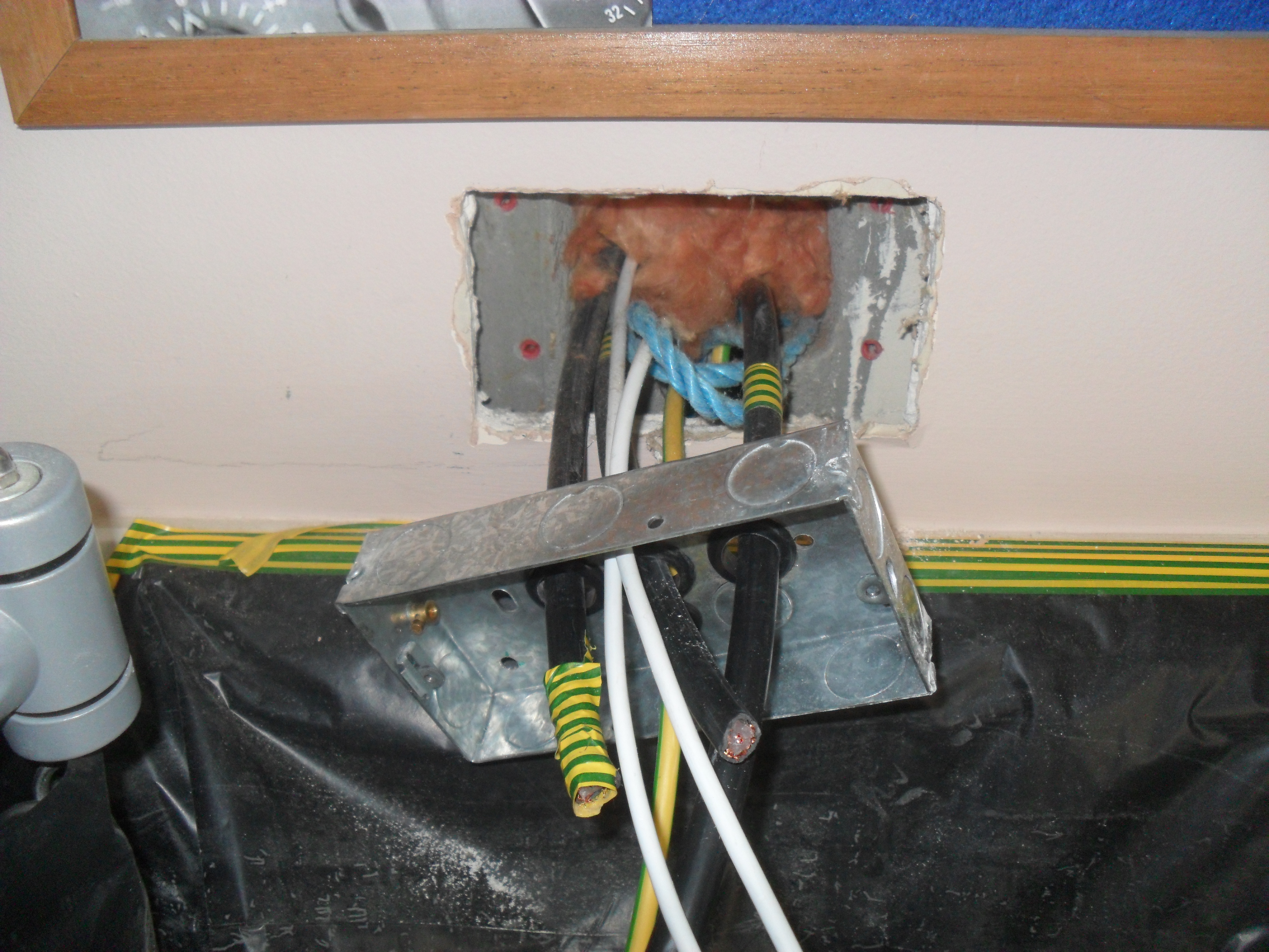
Backbox ready to be pushed into position, the cables you can see are three RG213 (x30, spare to loft and outside), signal cable looped from outside to the loft and a 10mm earth cable which goes to multiple earth rods, I earthed the x30 antenna bracket with a separate 10mm cable, also terminating at the earth rods.
RG213 soldered onto the faceplate bulkhead SO259.

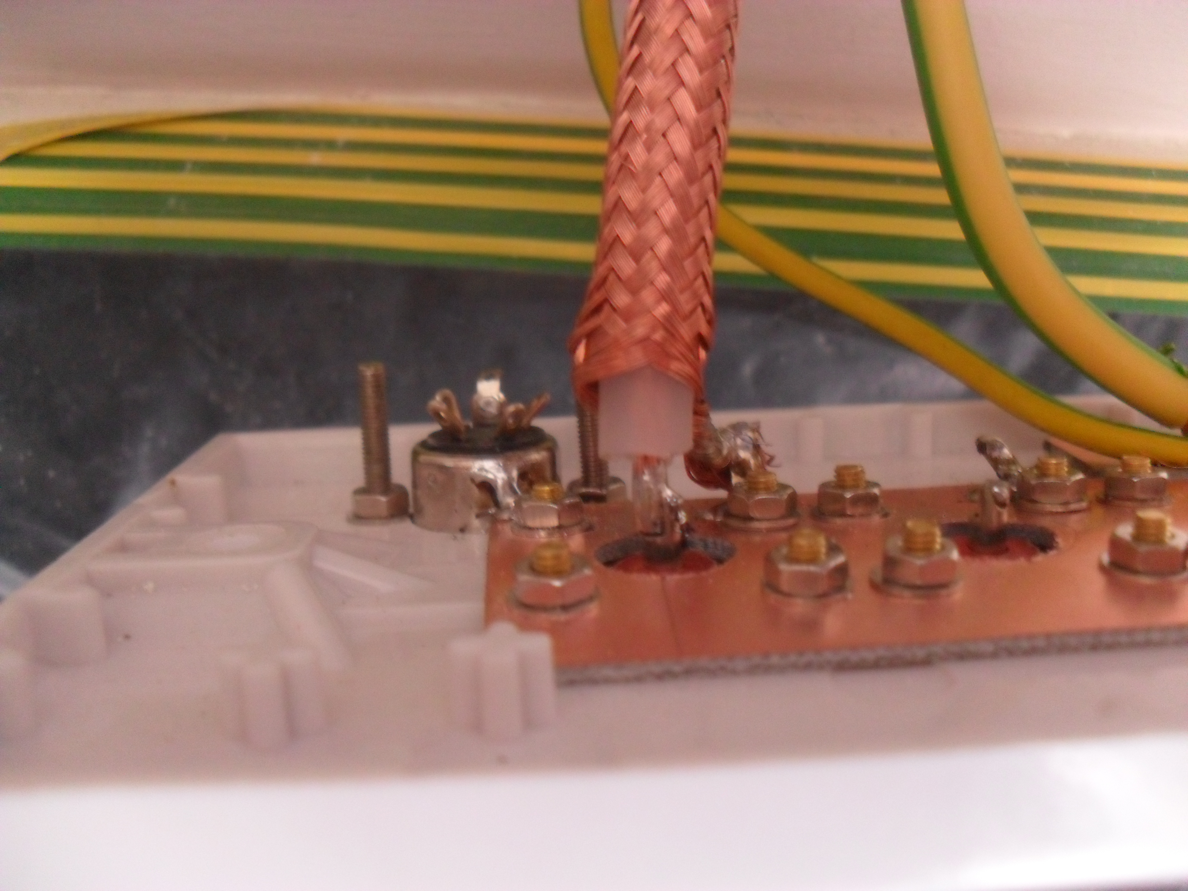
All antenna cables soldered and for good measure I shielded the connections with bonded copper tape.
Faceplate being eased into place.
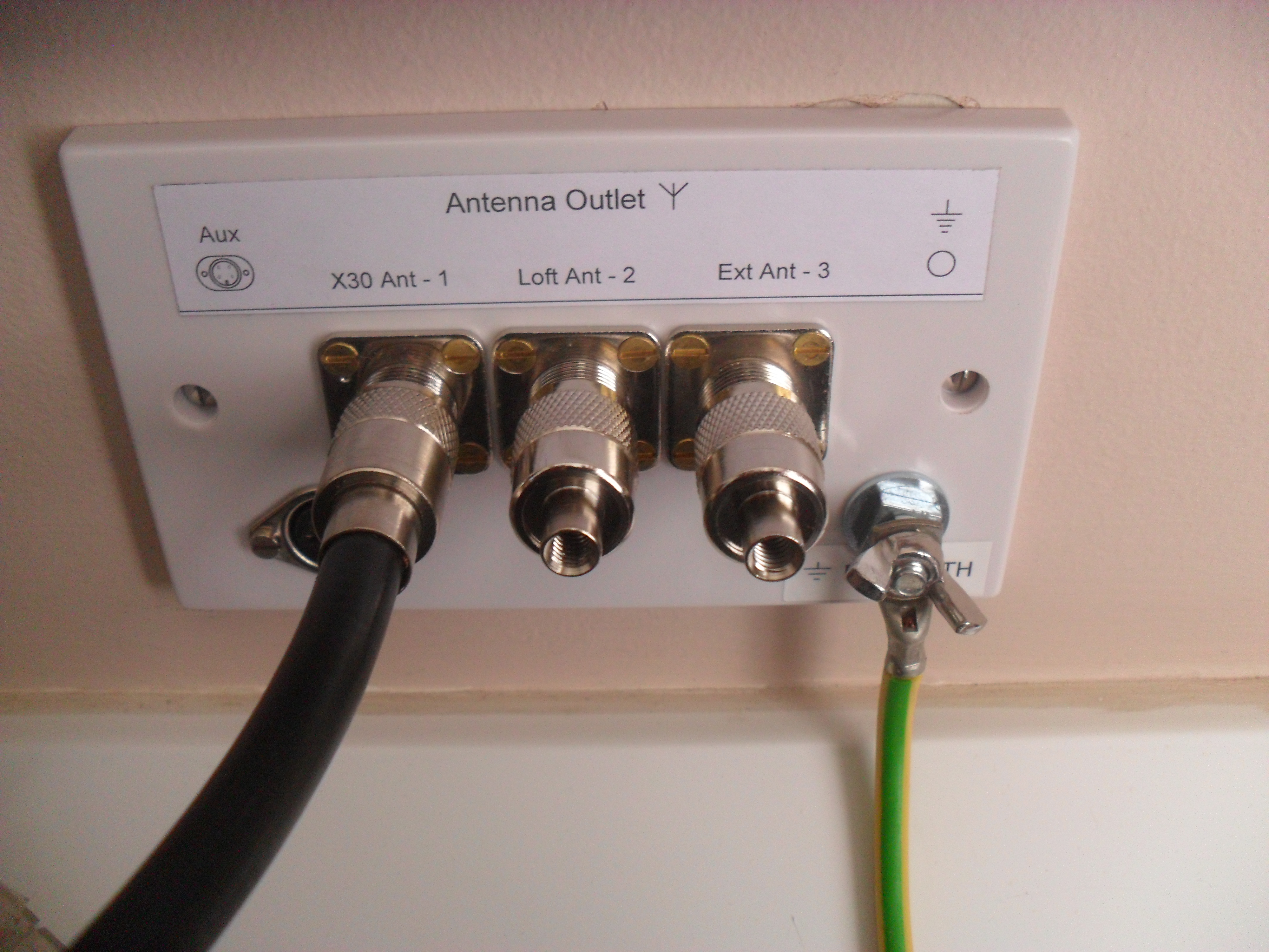
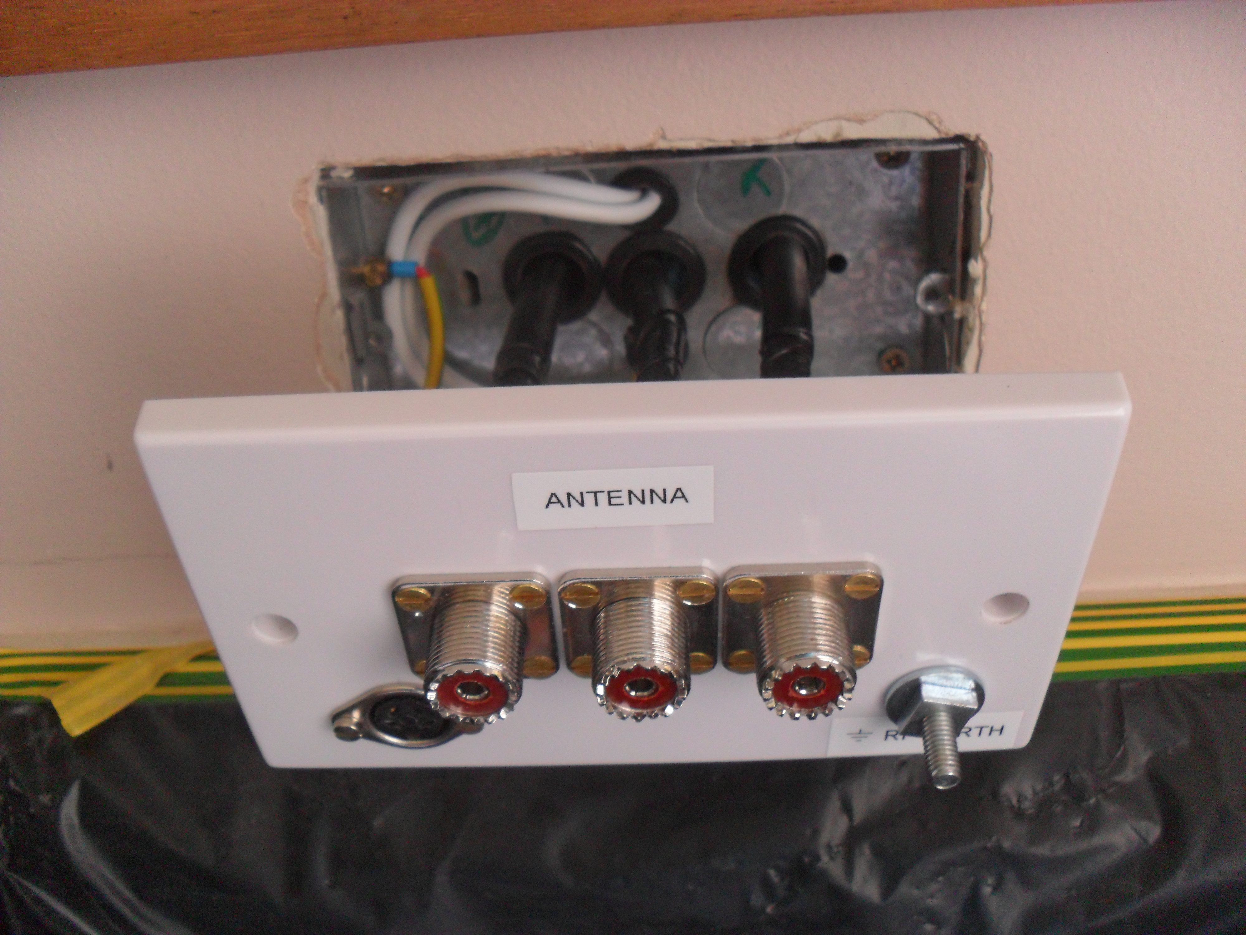
All secure, newly labelled faceplate with DIN socket for the signal cable, this will be used for a future requirement.
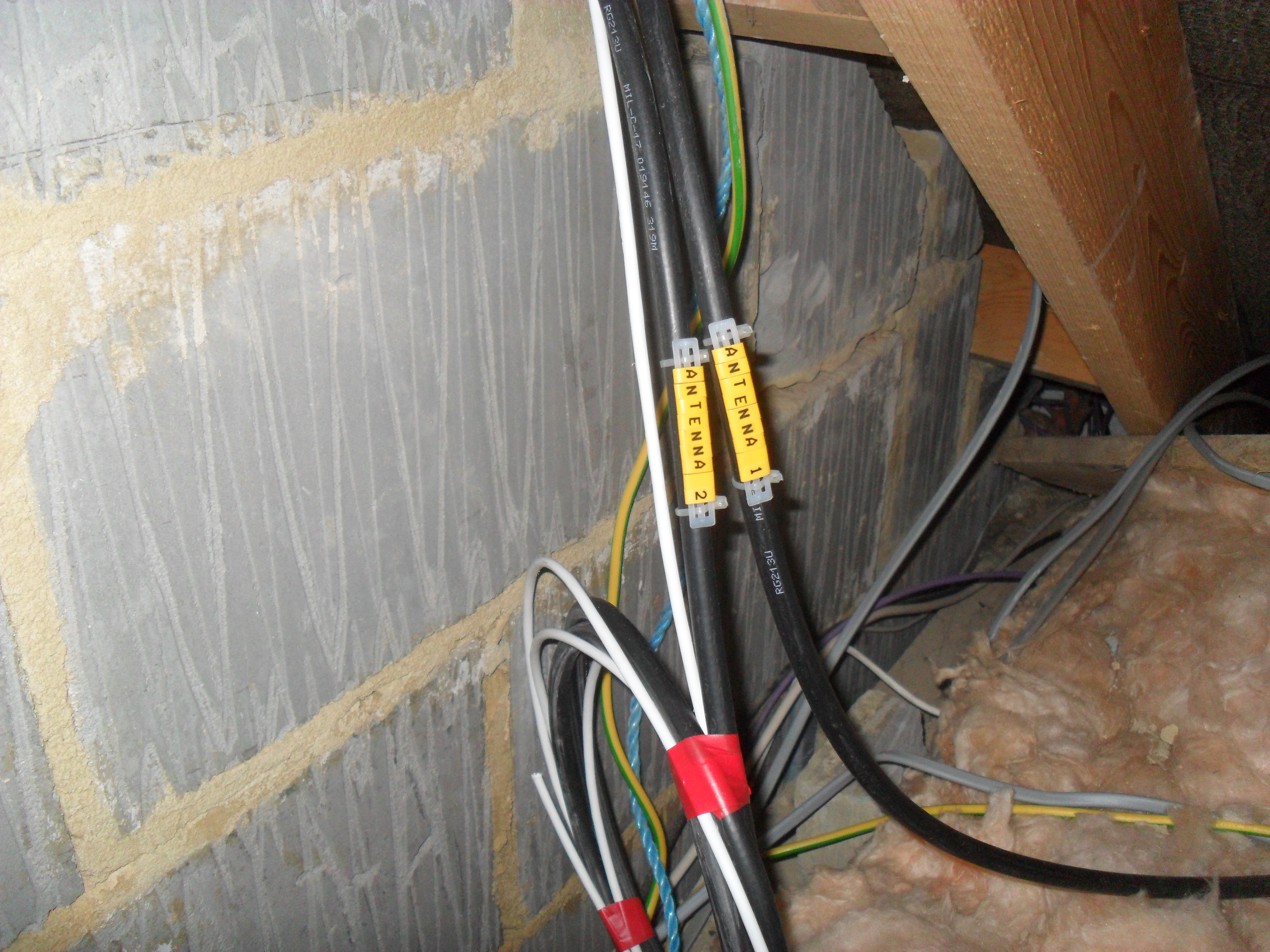
Cables identified in the loft.
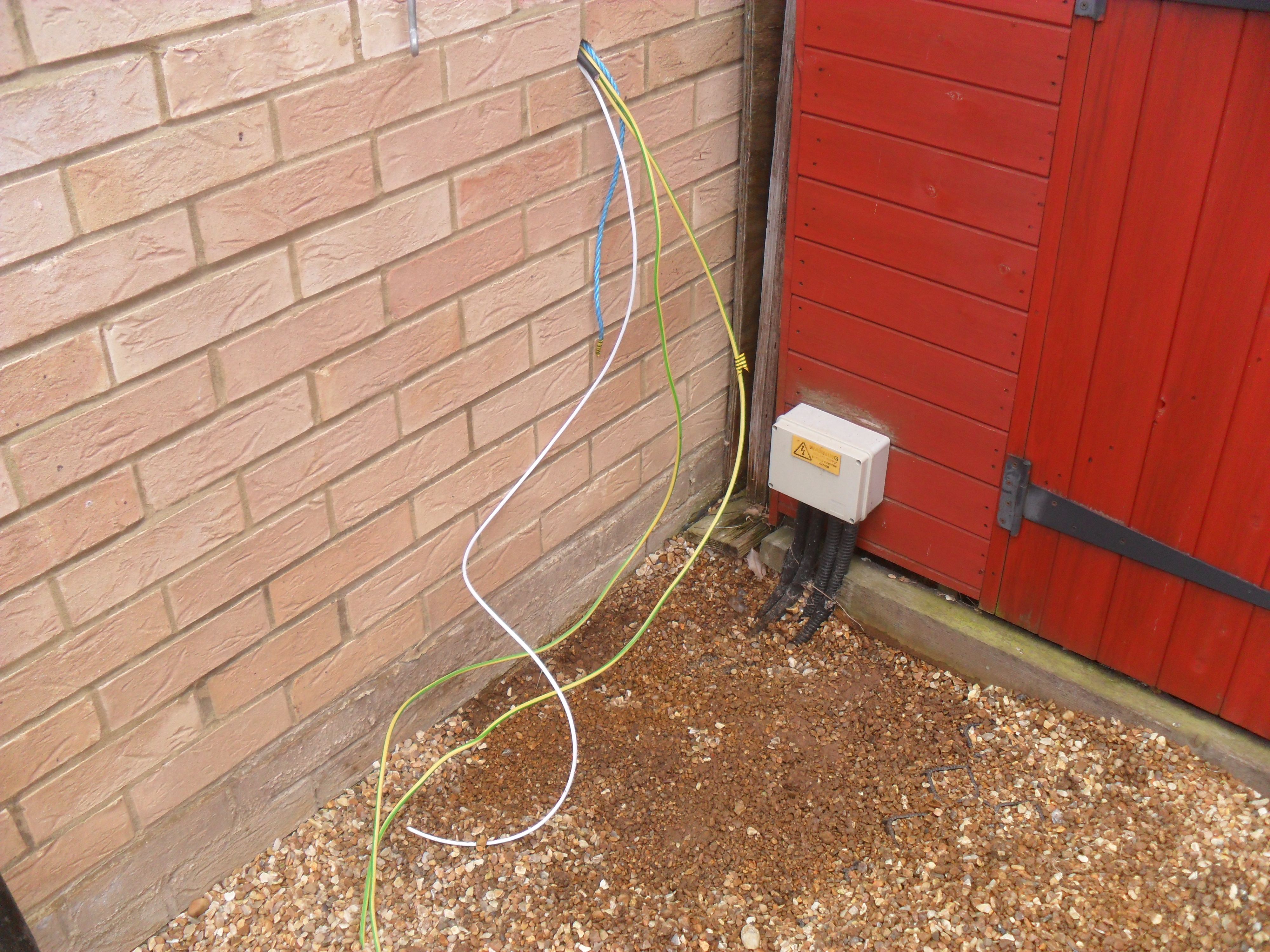
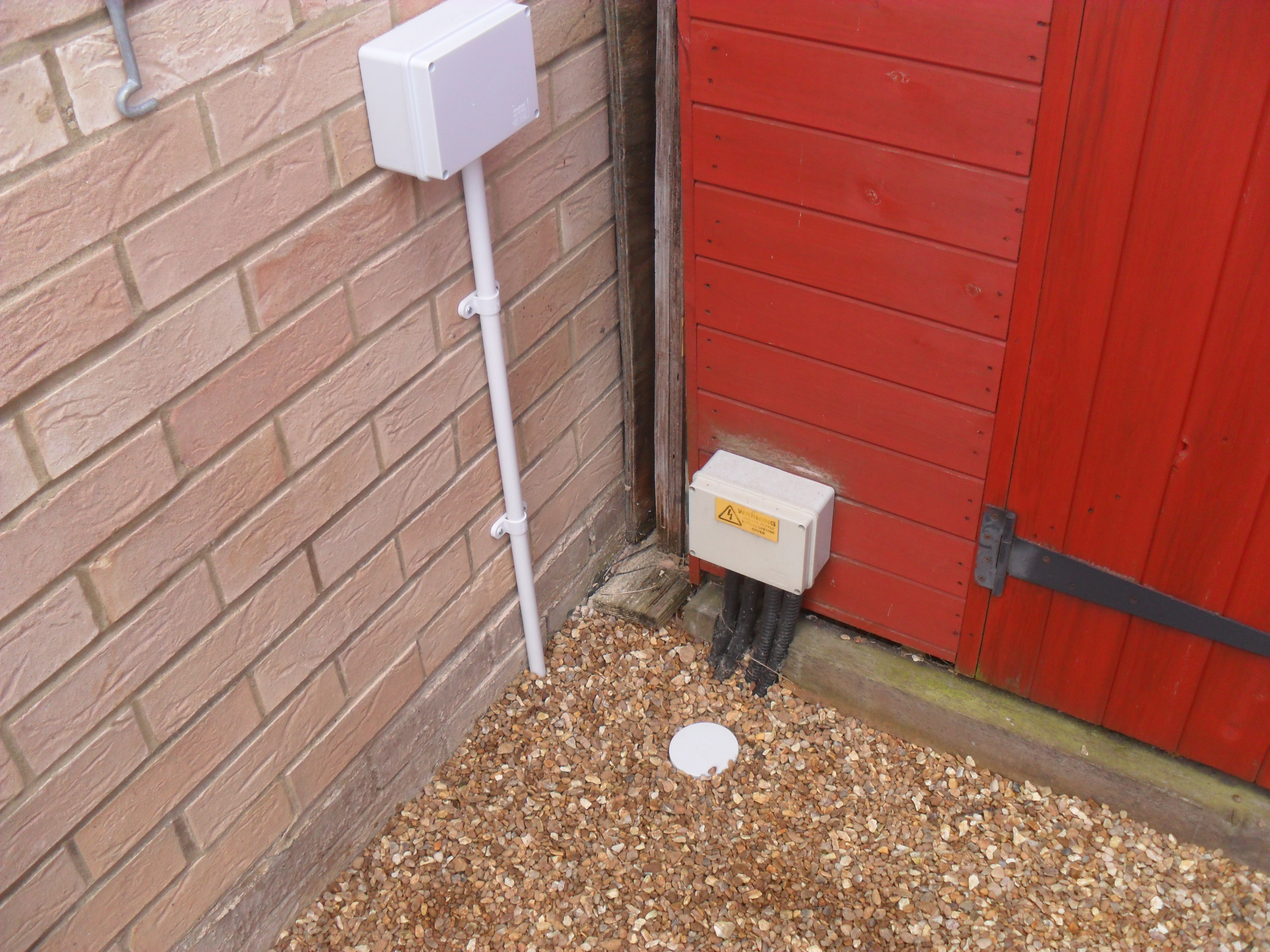
Ground for earth rod being prepared, this area does not get the sun and with the gravel on top, the heavy clay is always wet, so an ideal spot, I did have to be careful of existing cabling and the drains with run close to the wall. The rods and enclosures came from www.tlc.com.
Loose fit of the enclosure allowing measurements to be made for the conduit.
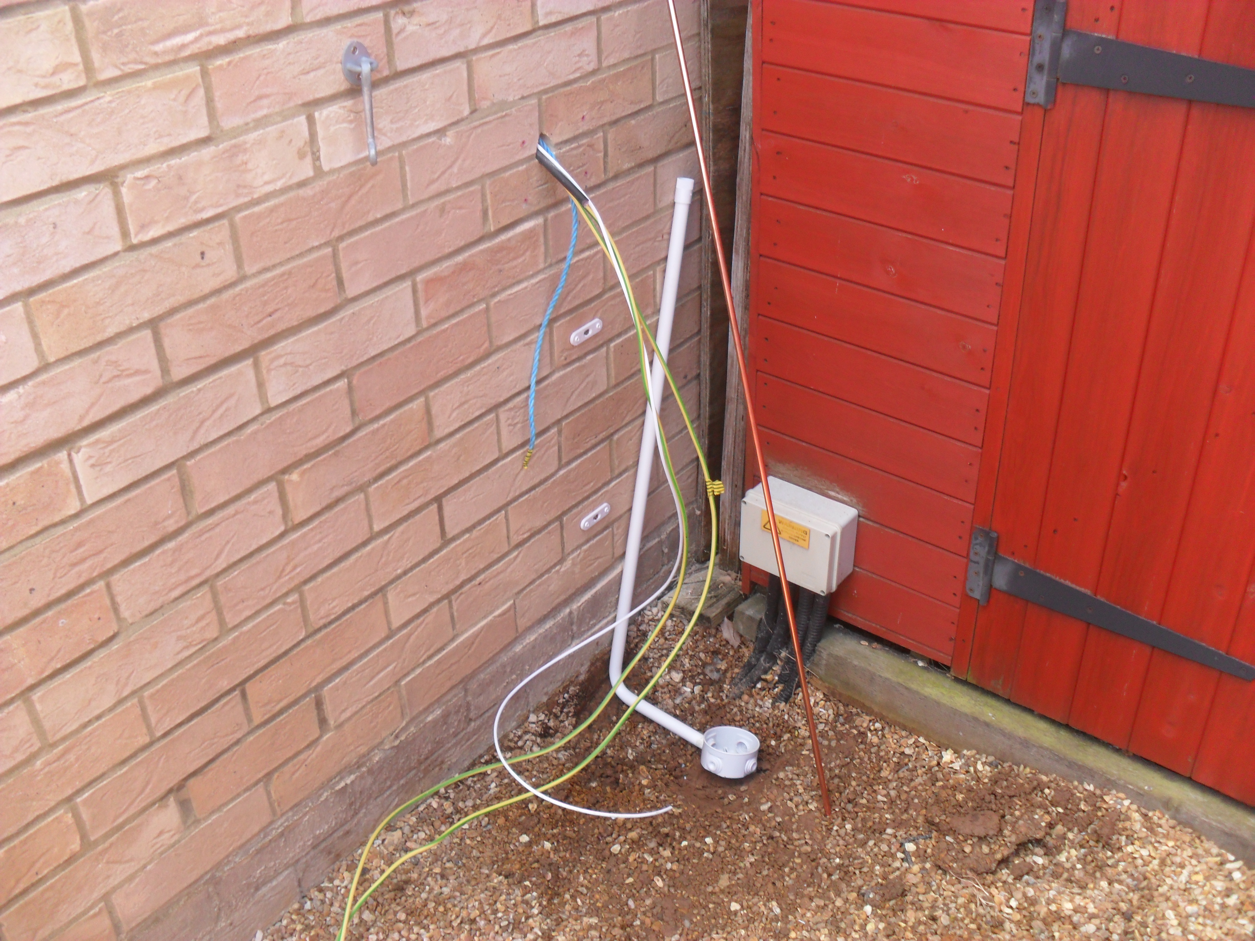
Conduit bent and saddles fitted, in the picture is the 4′ copper coated steel rod.
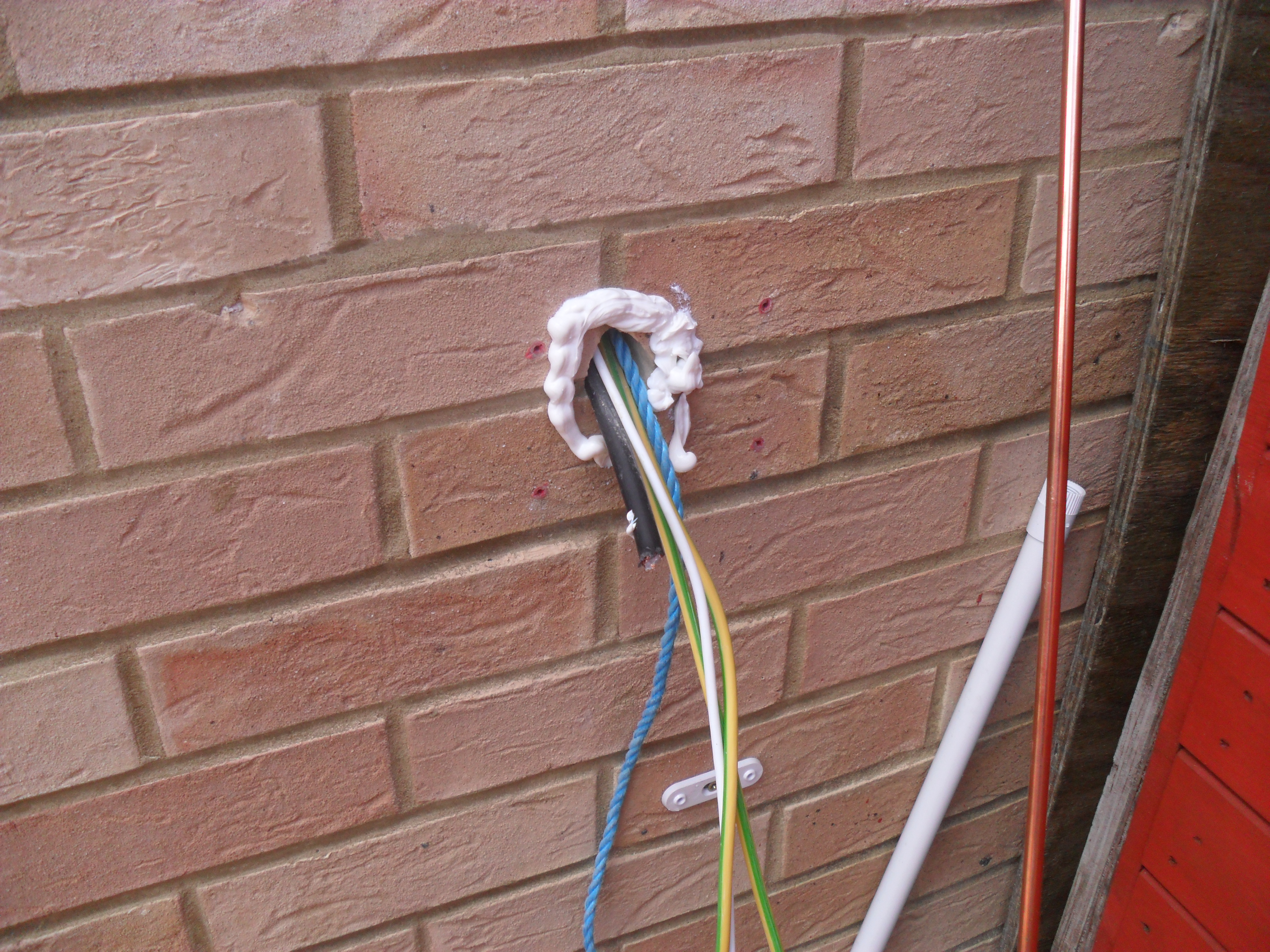
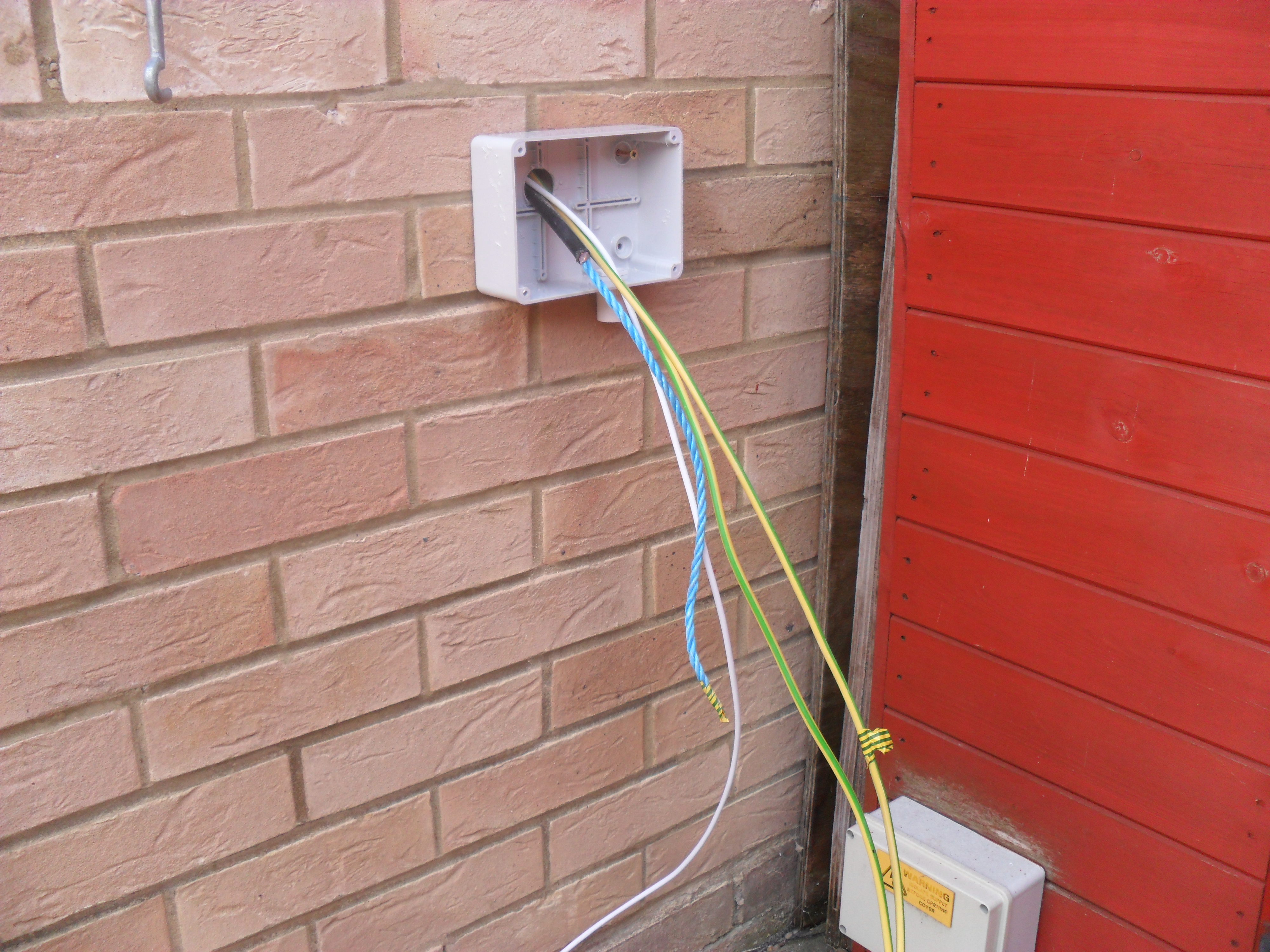
Silicon sealant around the cable exit, the enclosure will be screwed against this making a good water resisting seal, this sealant dries clear.
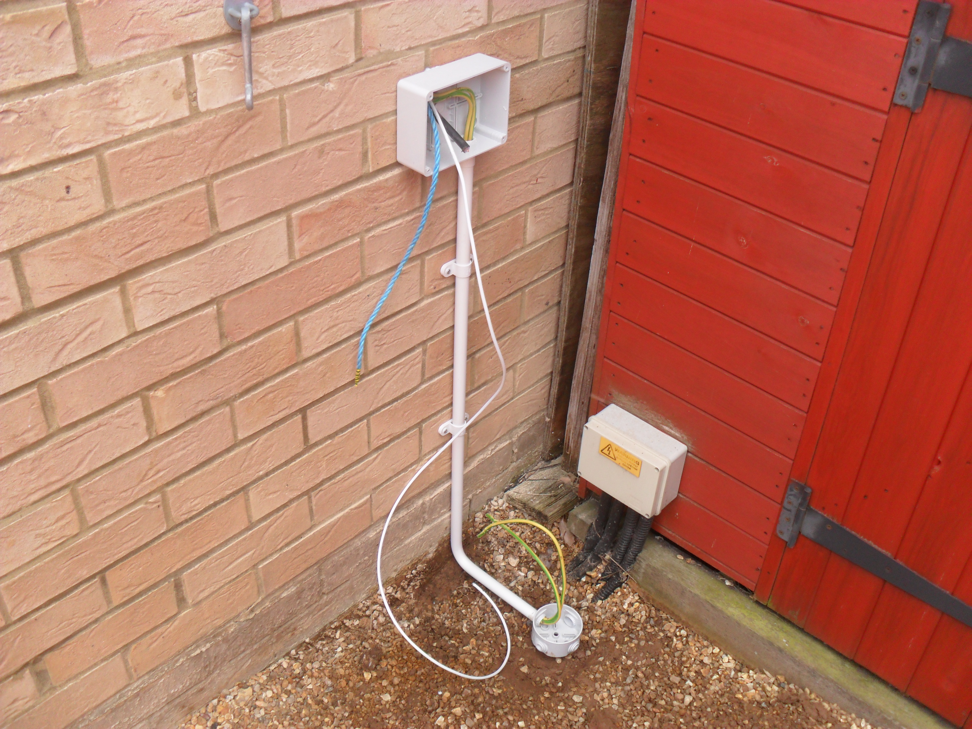
Hardware fitted and earth cables ready for termination.
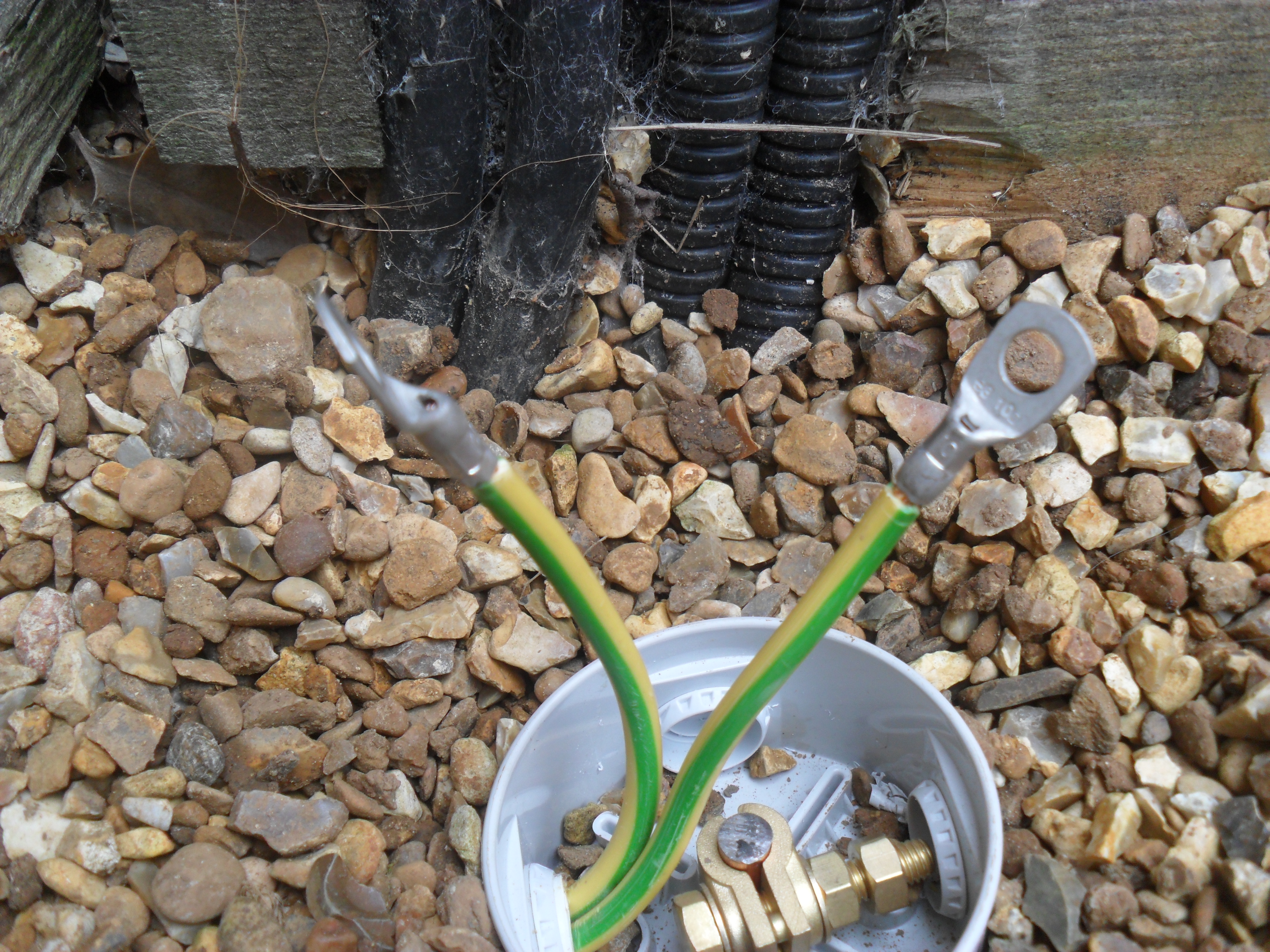
10mm lugs crimped and ready to be soldered for good measure.
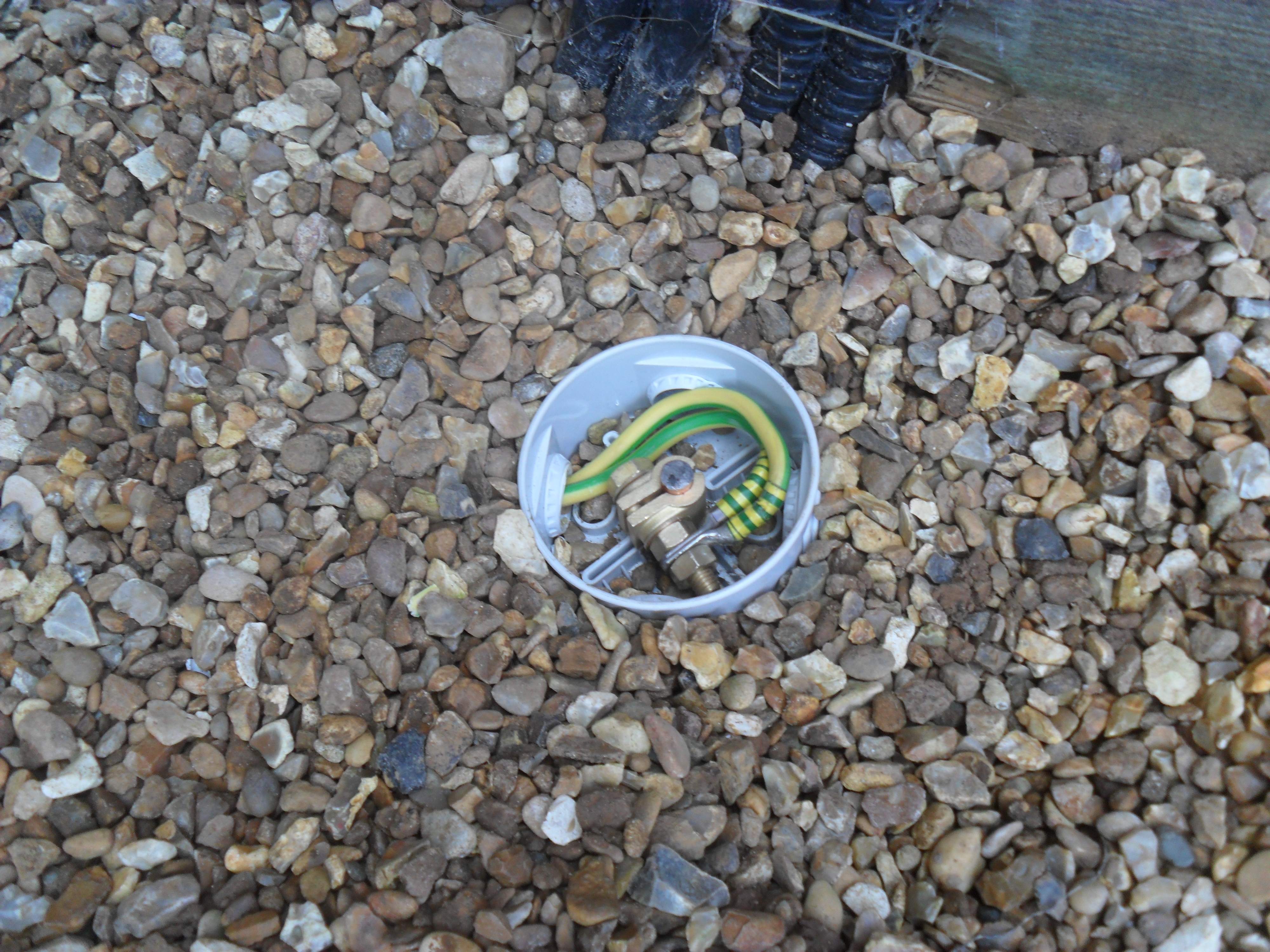
Connected to the rod clamp.
Lidded up.
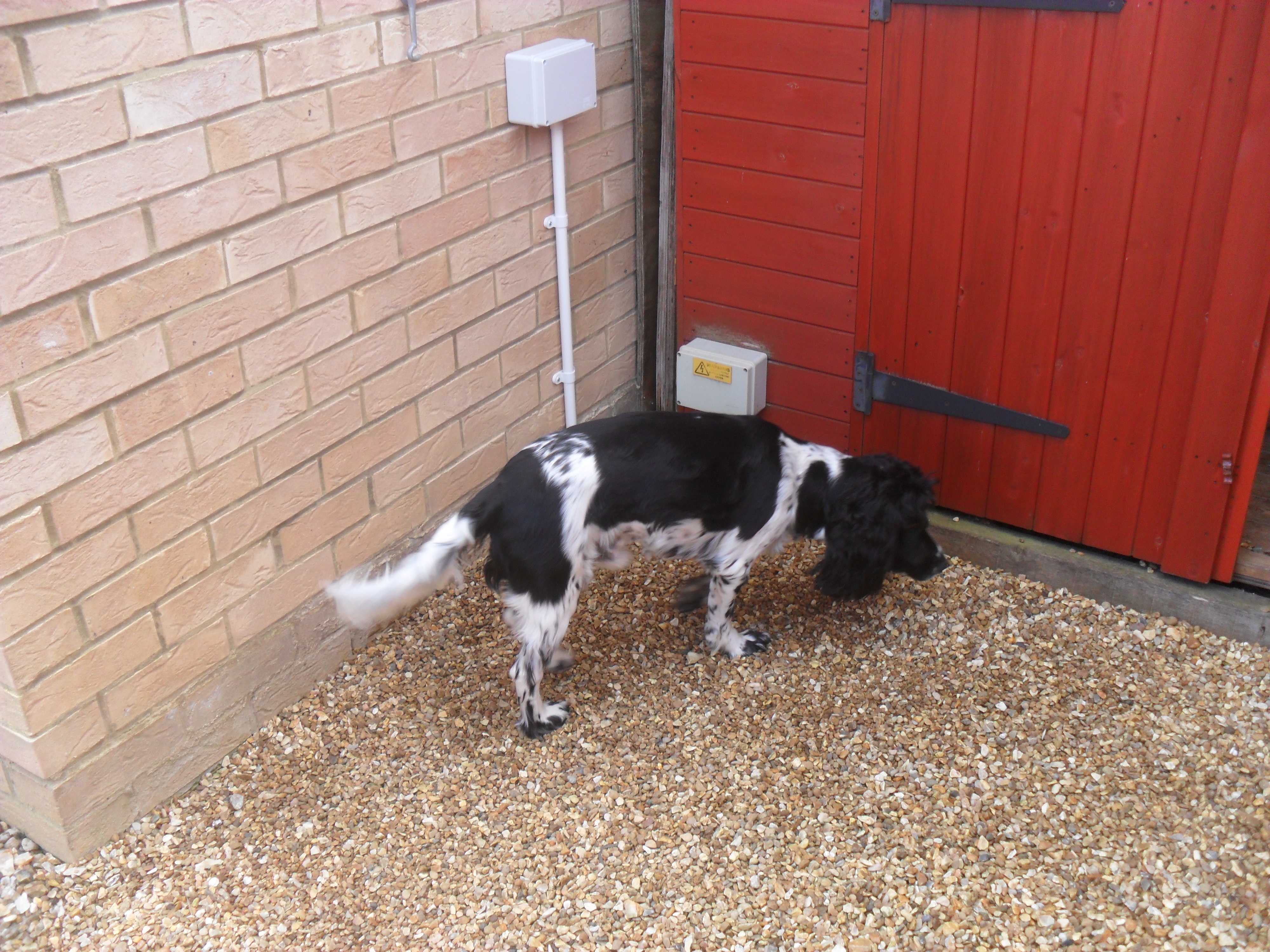
Even Barney couldn’t find it when covered.
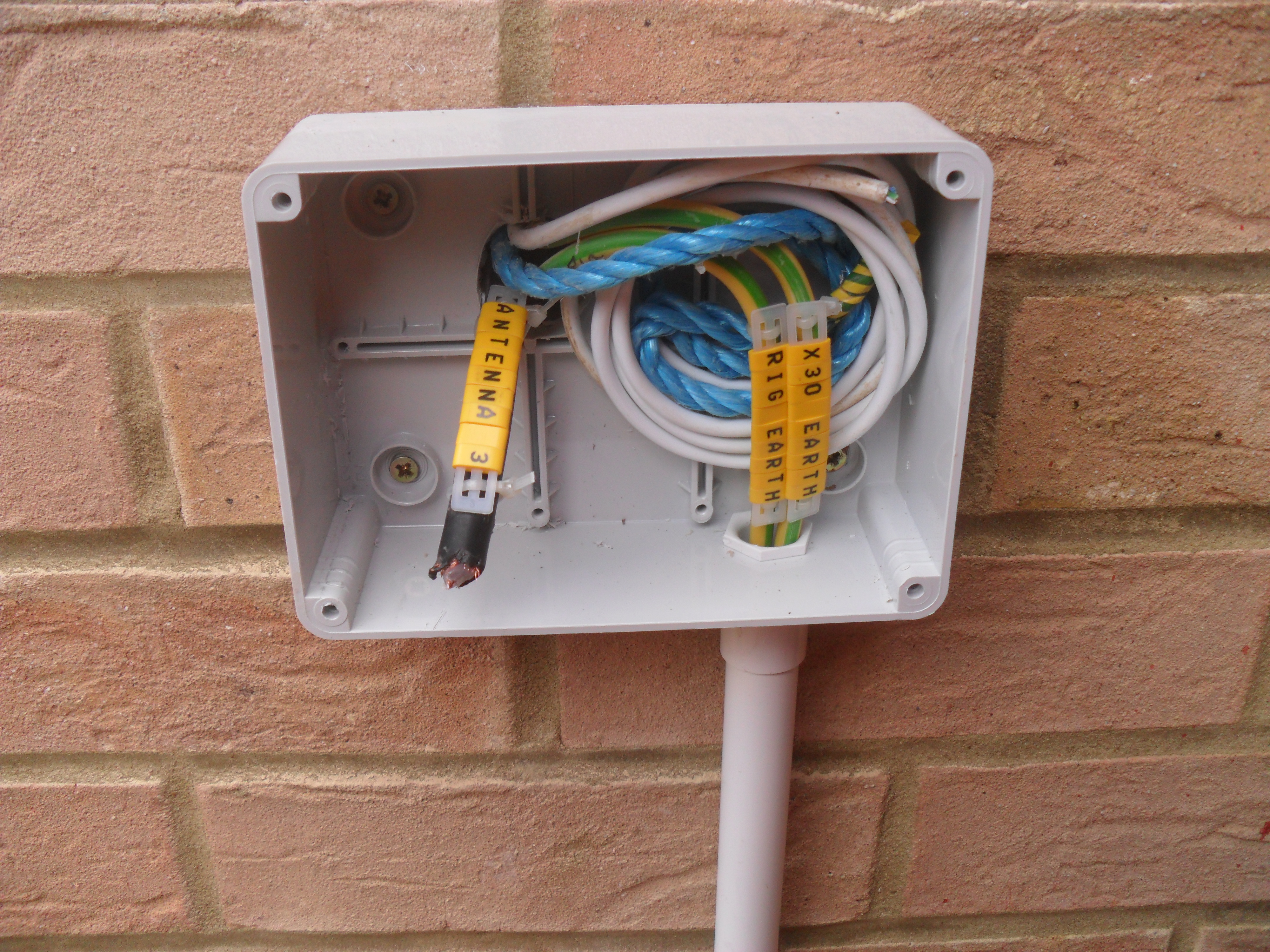
Inside the enclosure cables are labelled, I might put an earth block in here connected to a external antenna surge suppressor at a later date.
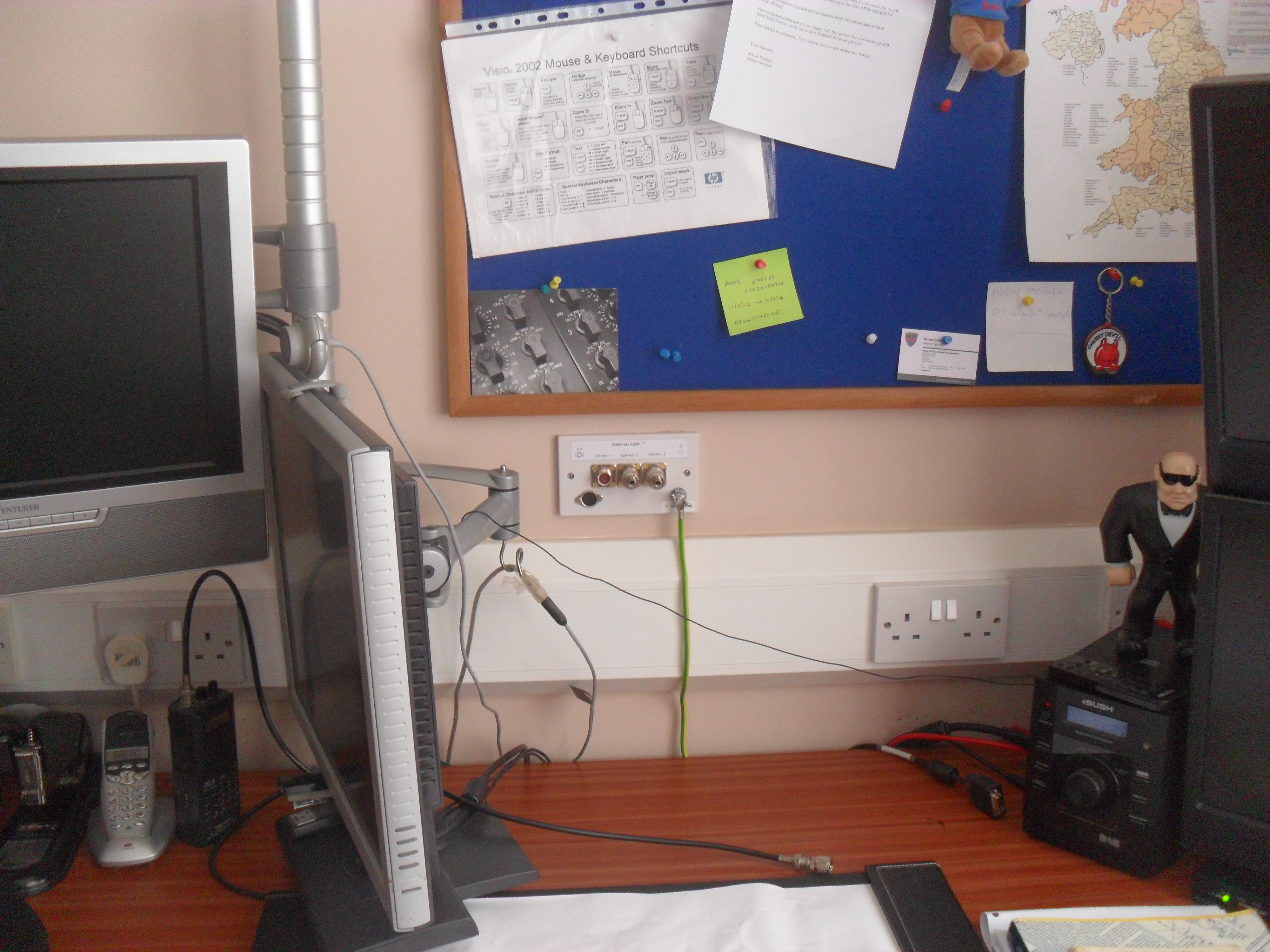
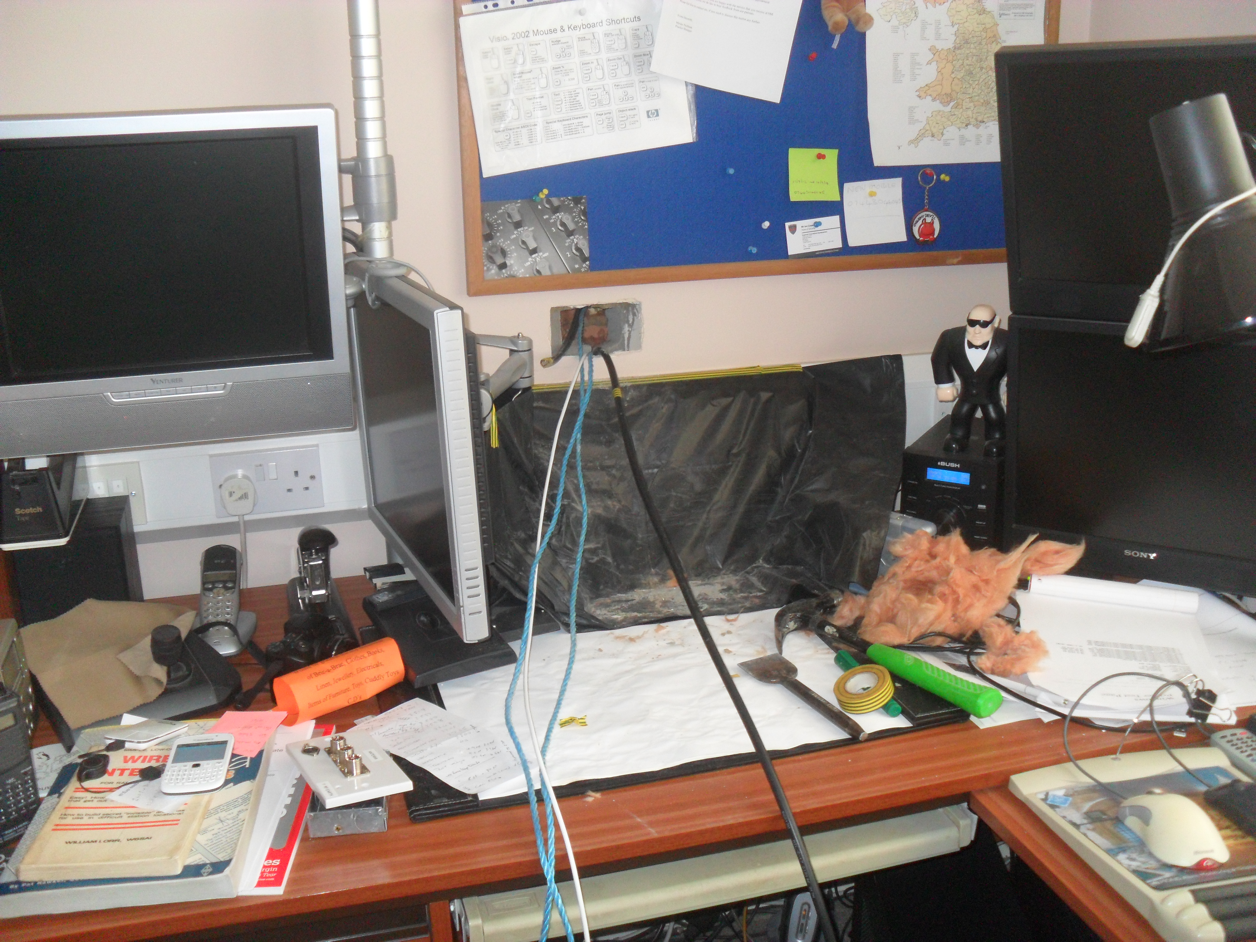
This where the faceplate lives in relation to the office, as you can see it is absent of radio kit as I do not own any yet, but I’m working on it!
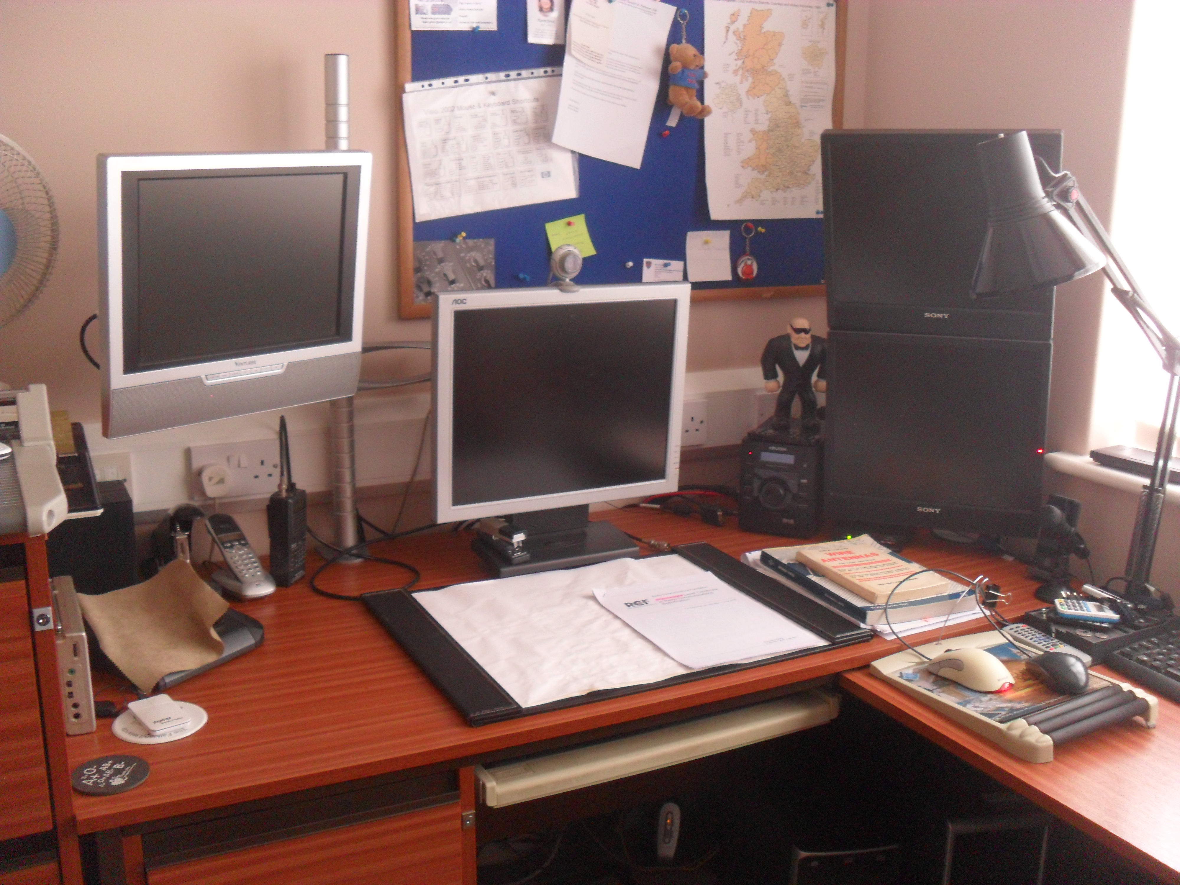
Office put back together and faceplate covered by PC monitor, now the route to the loft and outside is established, modifications or extensions to the cabling can be done relatively easily.
The next stage is the addition of multiple earth rods, so please keep checking back.
Rain & Temp Trends

I’ve added a new Rain & Temp Trend page, this script is from Wildwood Weather and I have put a link to this site in – Links > Useful Links > Weather Website PHP Scripts and Software.